Lesson Category: Mini / Helix

Replacing the Control Panel

Remove Side Panels

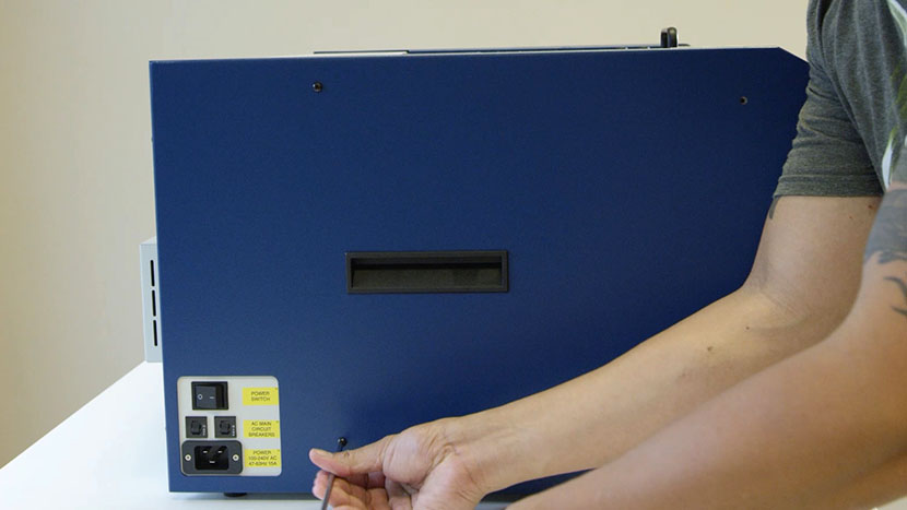
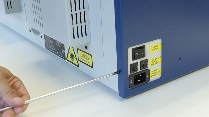
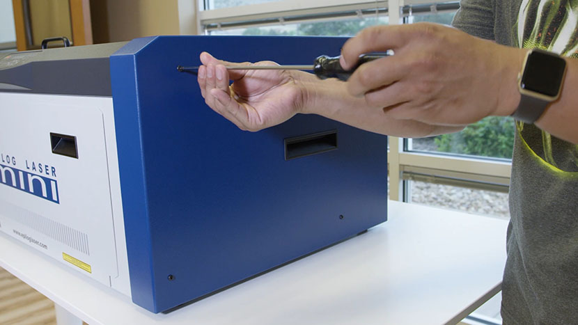
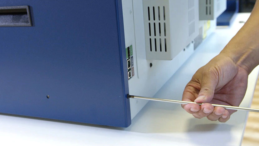
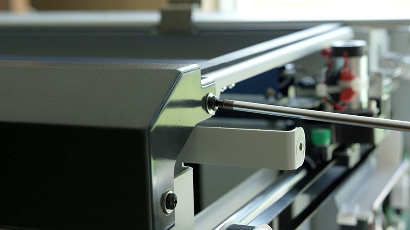
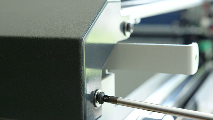
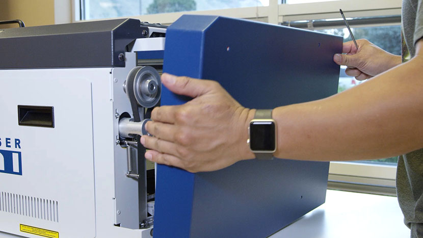
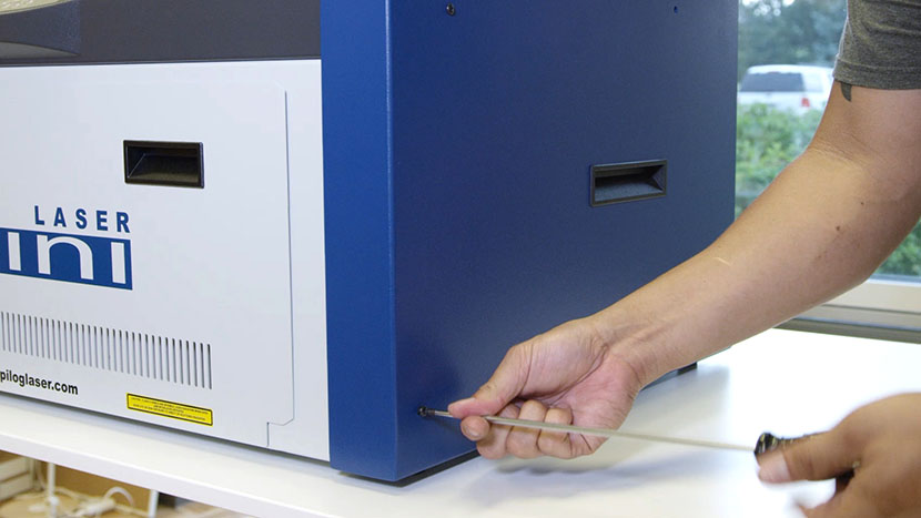
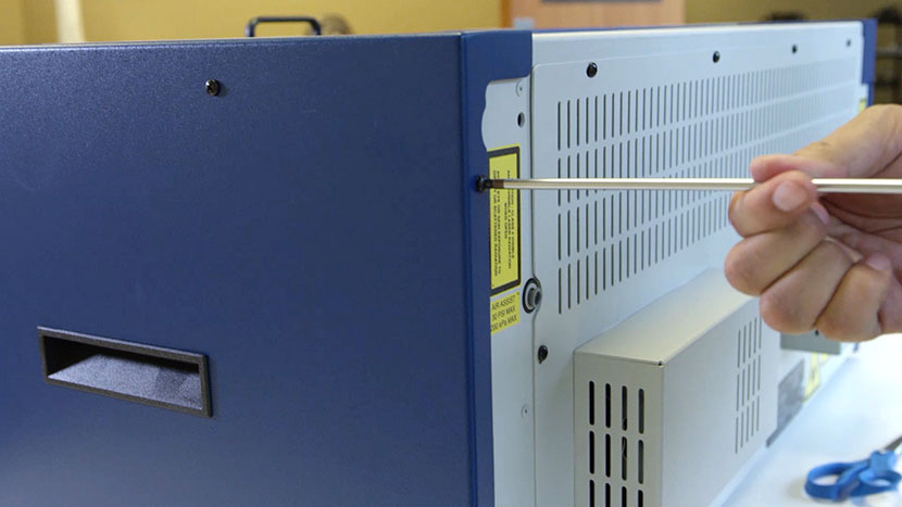
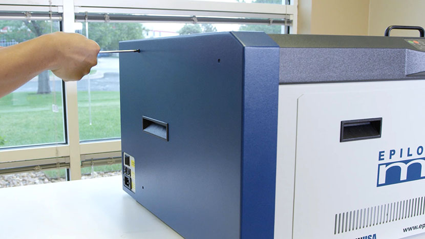
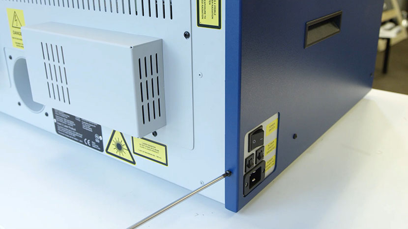
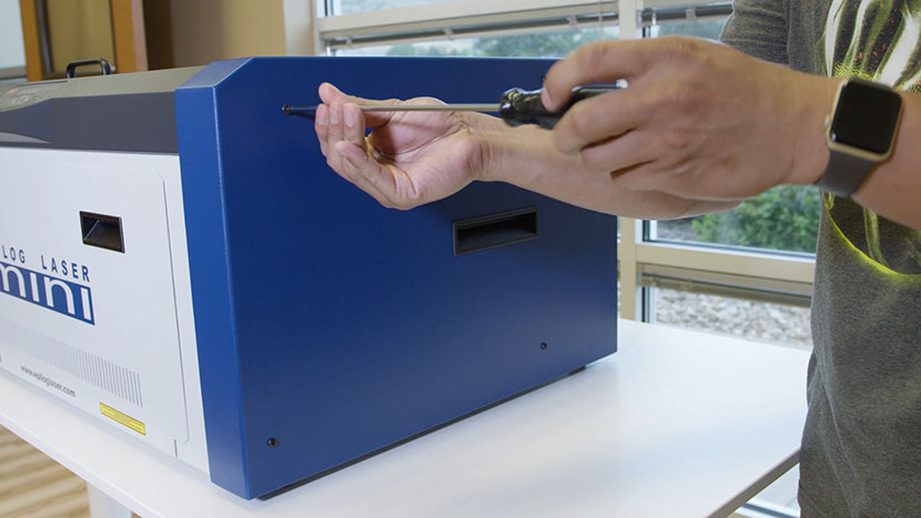
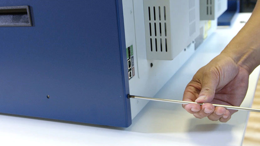
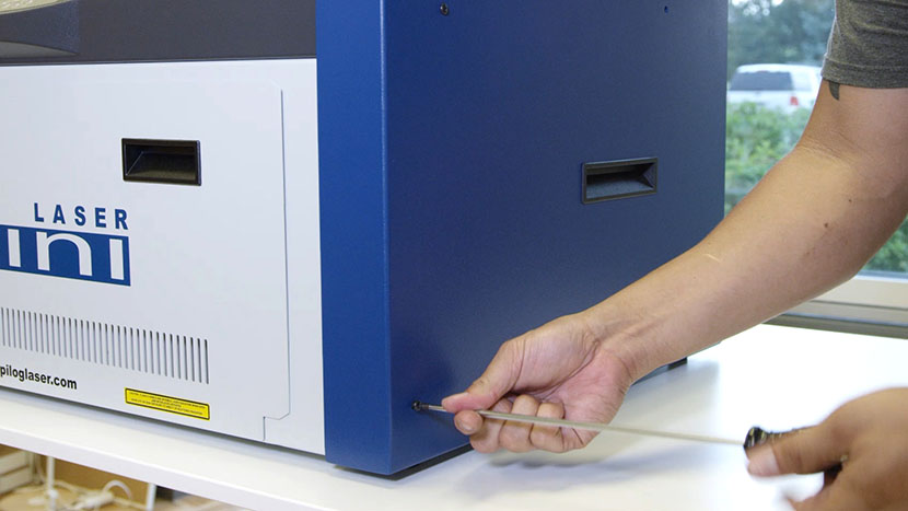
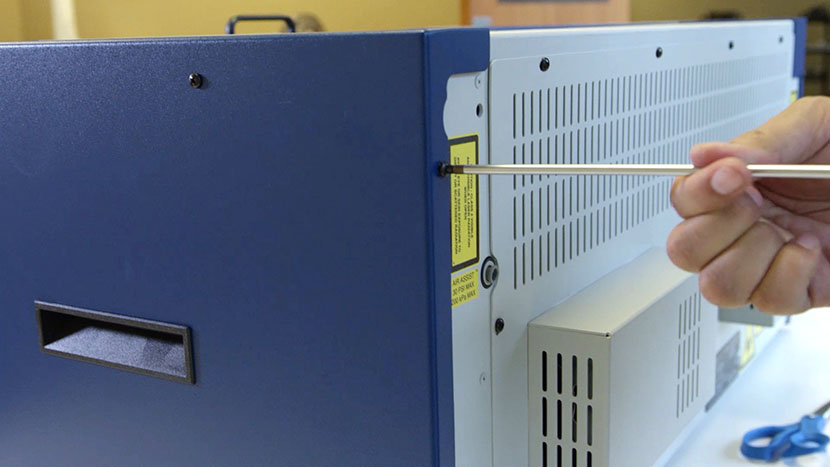
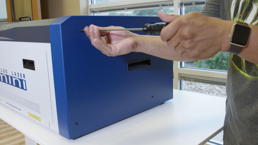
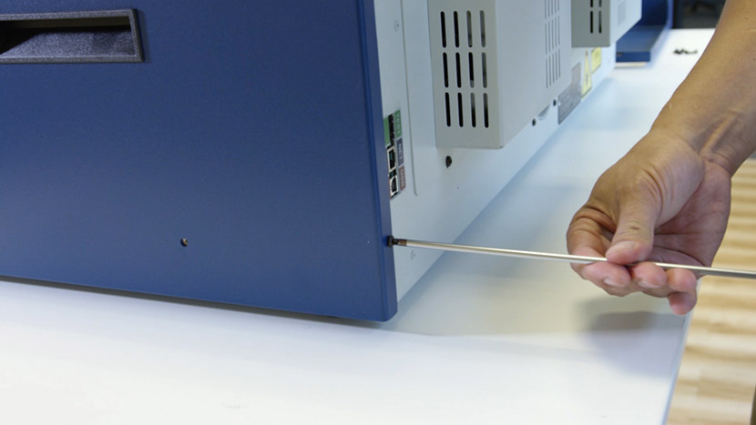
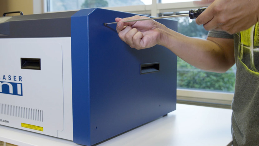
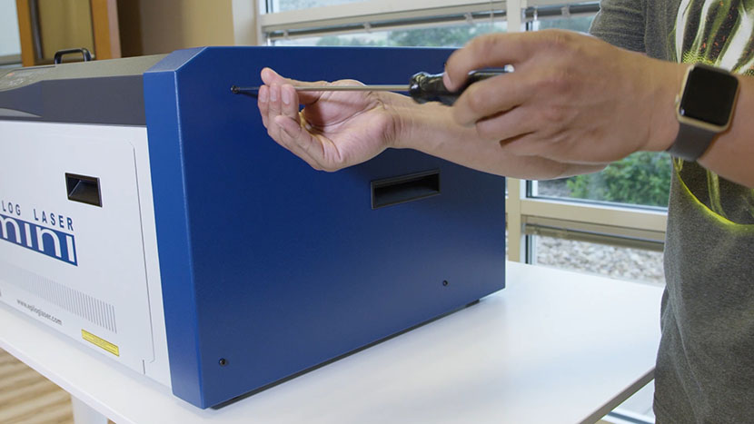
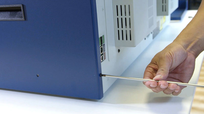
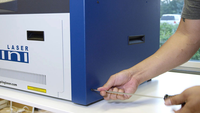
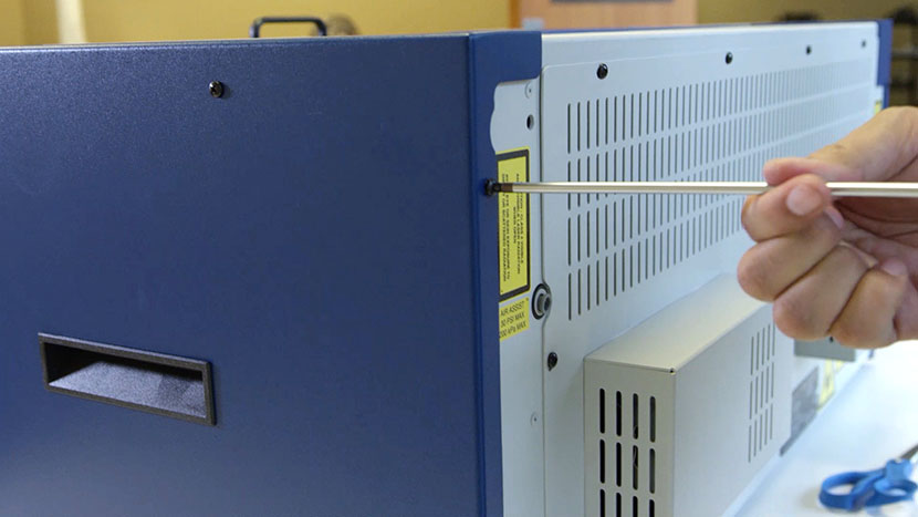
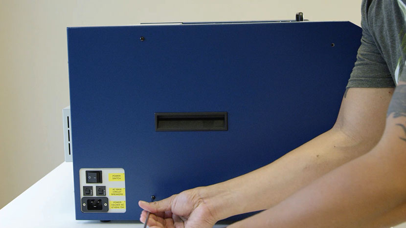
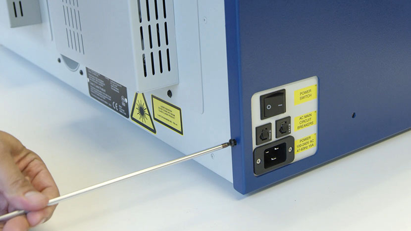
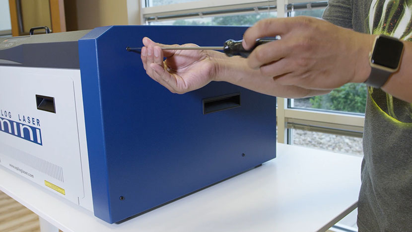
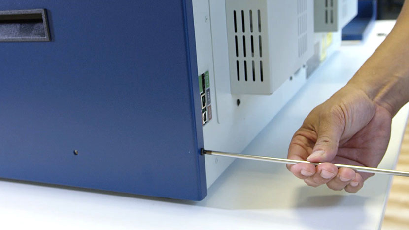
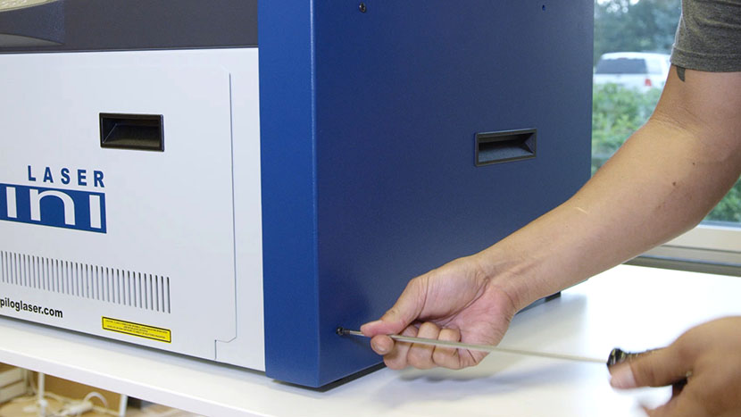
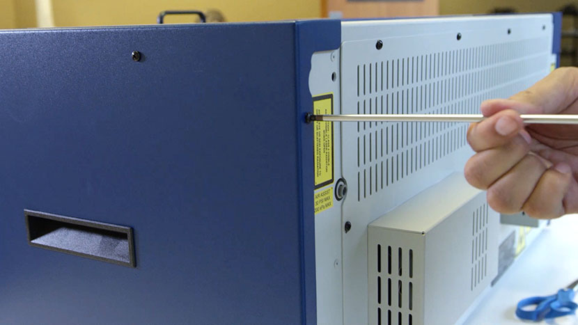
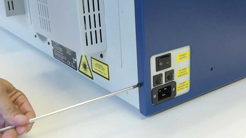
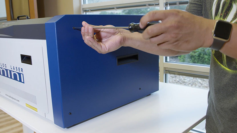
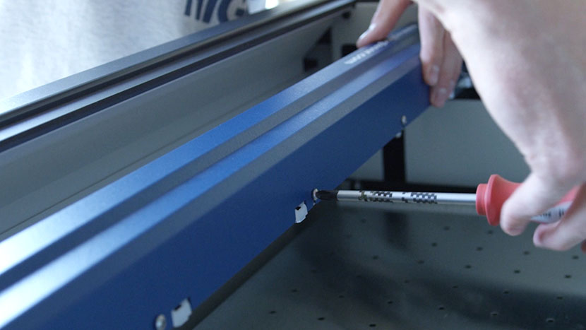
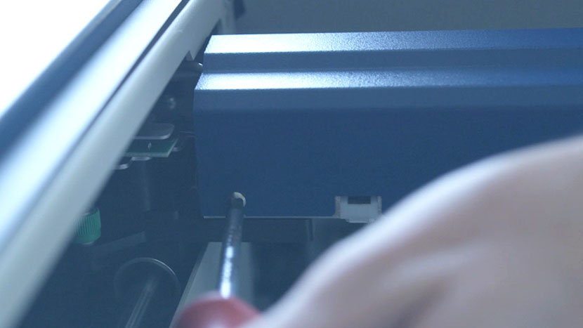
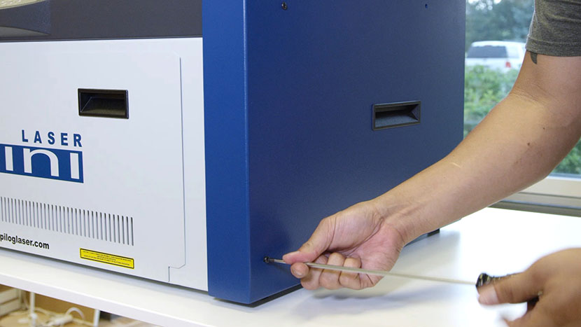
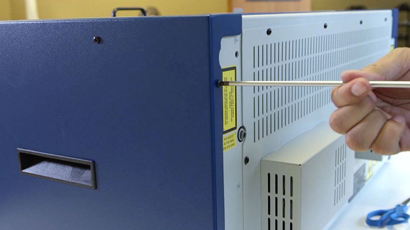
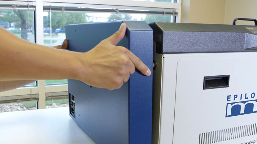
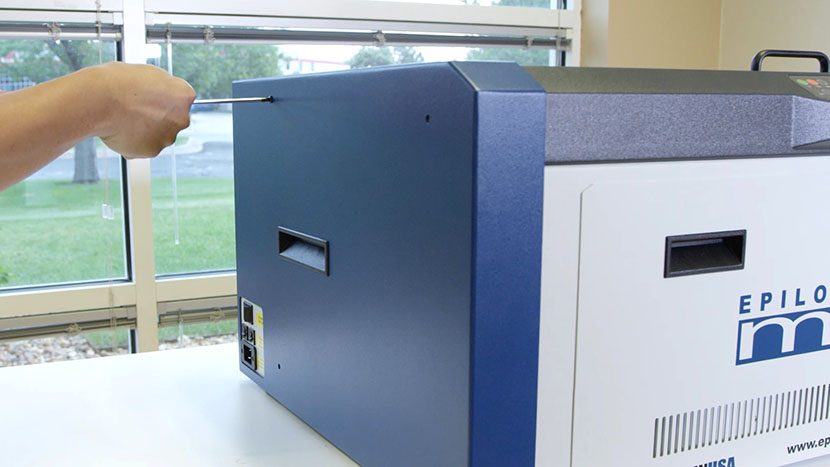
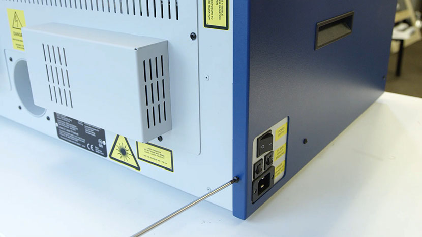
Remove the left side panel by loosening the four screws on its main face, as well as the two screws on the back.

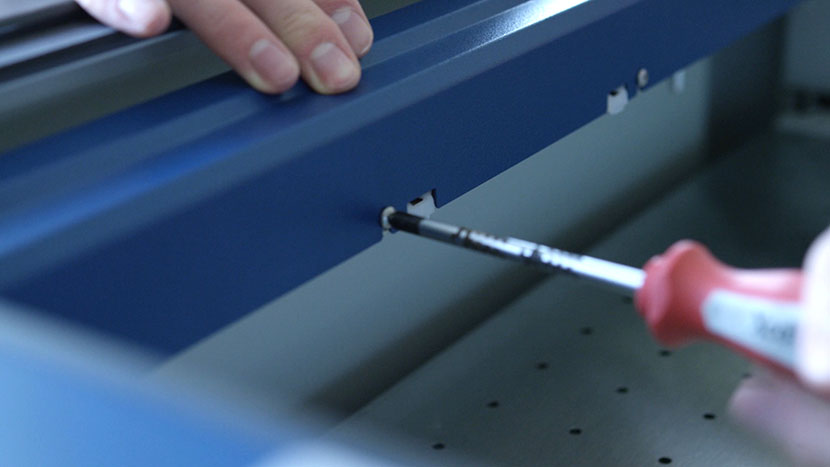
Removing the screws on the left panel's main faceRemoving the screws on the left panel's back face

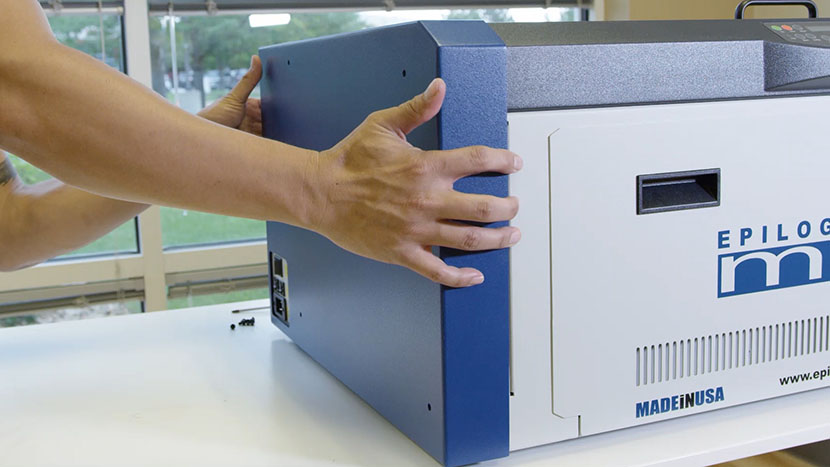
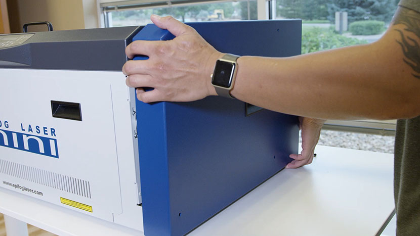
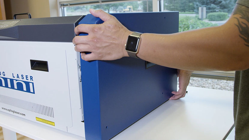
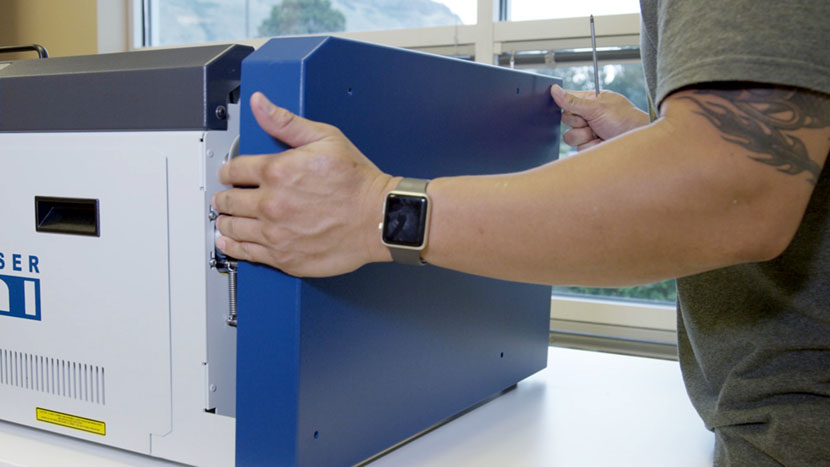
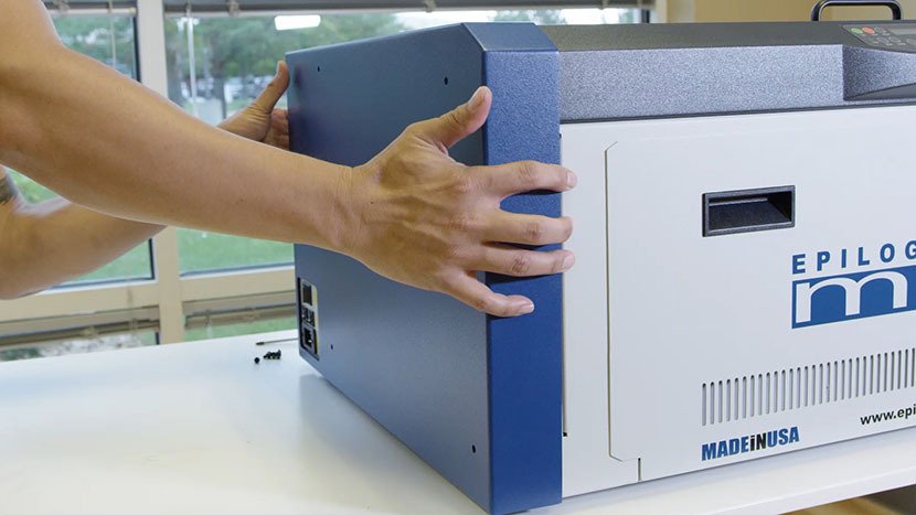
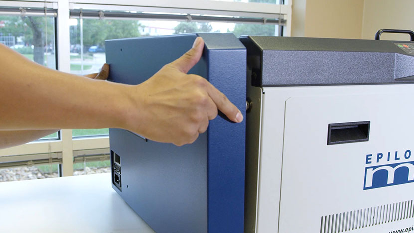
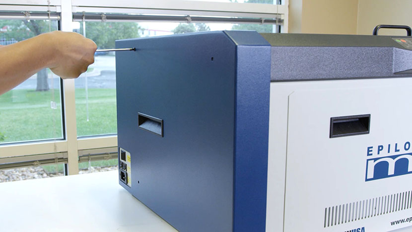
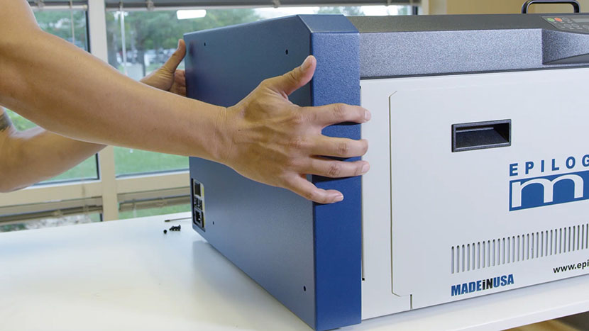
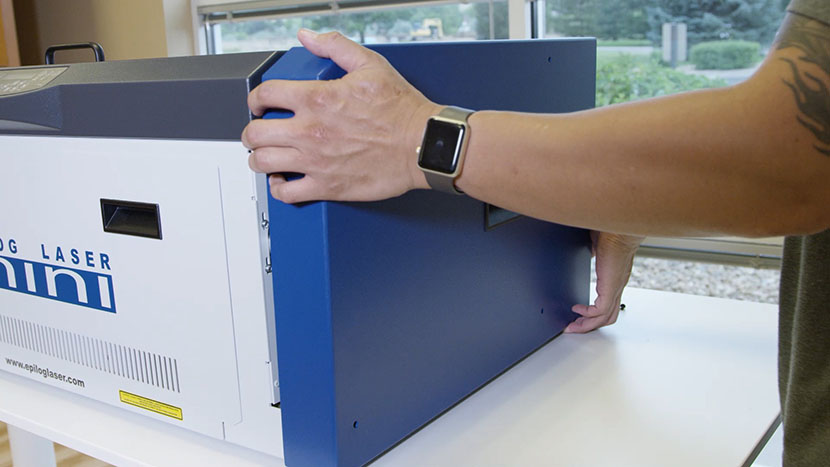
Pulling the left panel off of the chassis

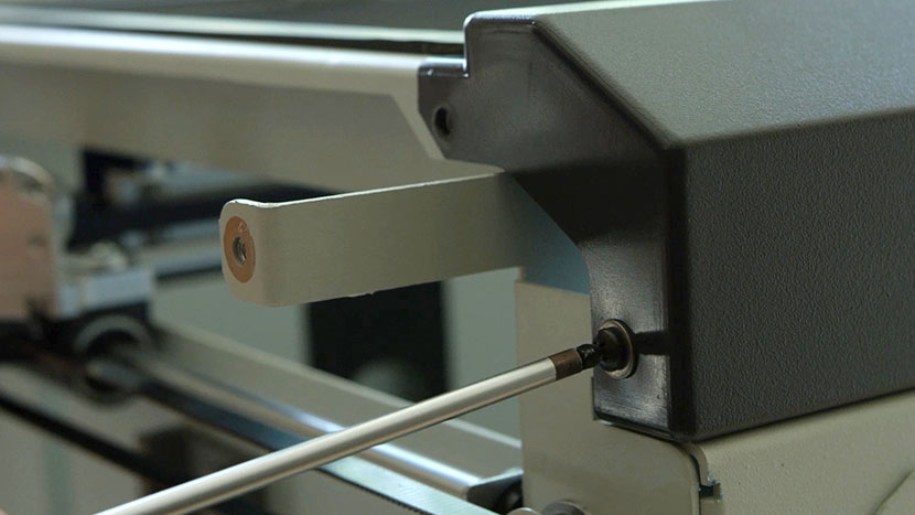
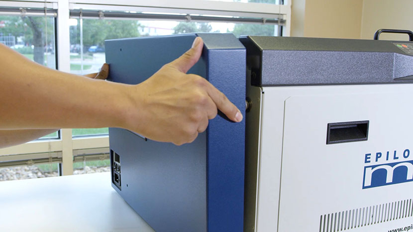
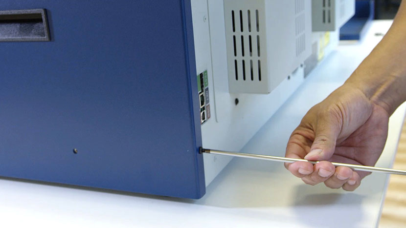
Remove the right side panel by loosening the four screws on its main face, as well as the two screws on the back.

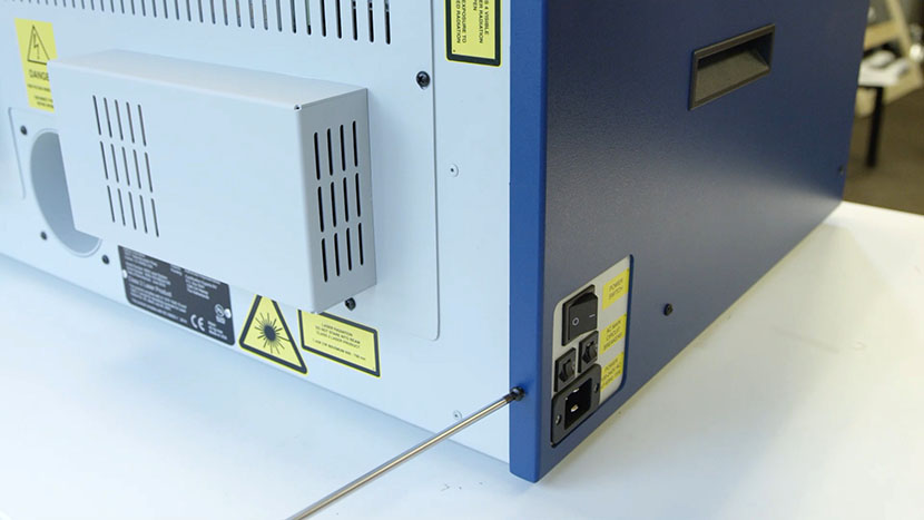
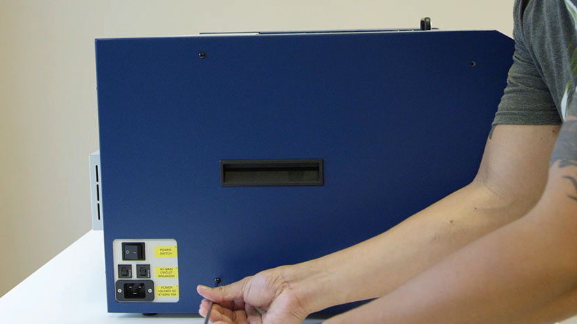
Removing the screws on the right panel's main faceRemoving the screws on the right panel's back face

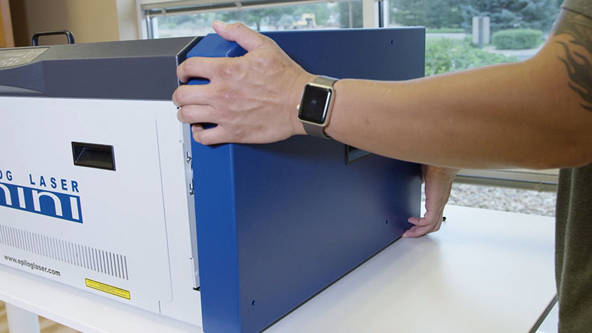
Pulling the right panel off of the chassis

Remove Old Keypad

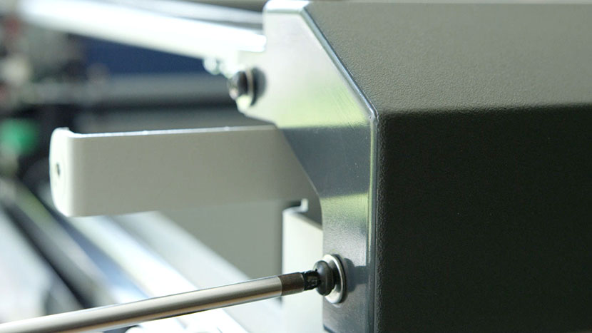
Remove the four outer screws, two on each side of the bezel.

Removing the screws that secure the right side of the control panel bezelRemoving the screws that secure the left side of the control panel bezel

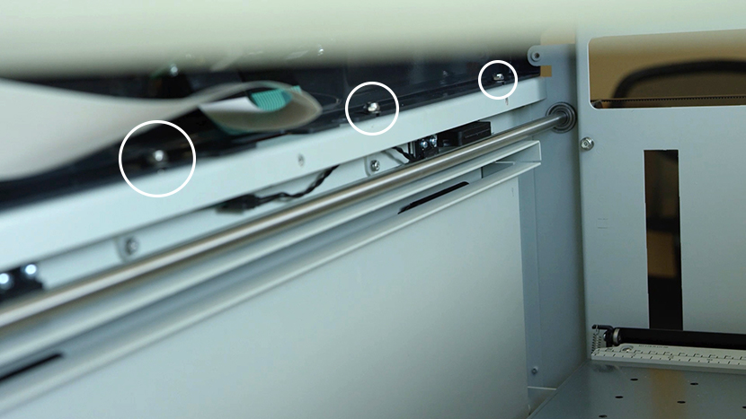
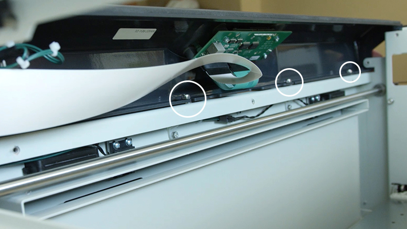
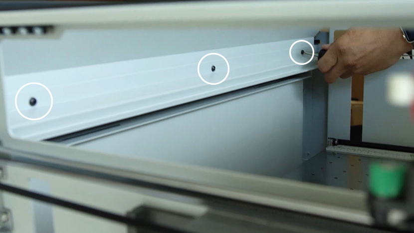
Remove the three screws securing the centers of the two panels on the inside of the bezel.

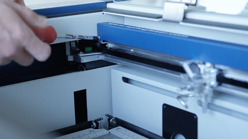
Removing the three screws that secure the centers of the interior panels

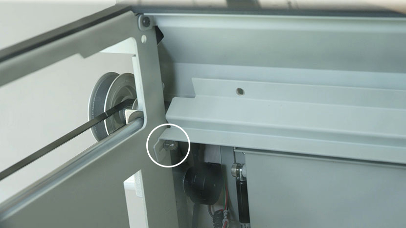
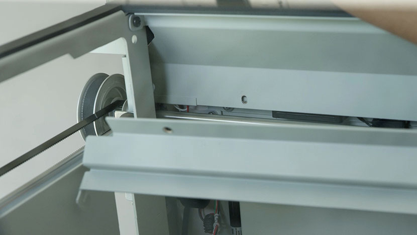
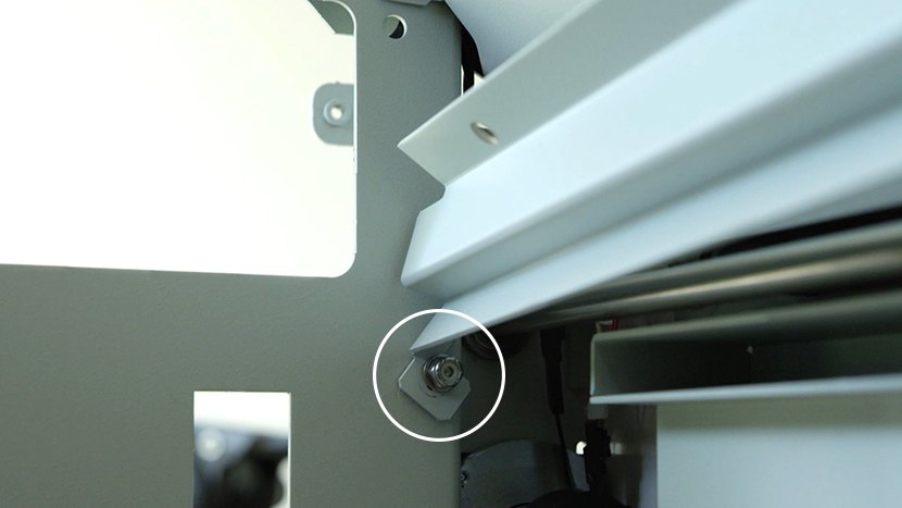
Loosen the two 3/16 inch nuts at the bottom corners of the bottom interior panel. Then remove the bottom panel.

One of the two bottom nuts that need to be loosened to remove the bottom panelRemoving the bottom panel

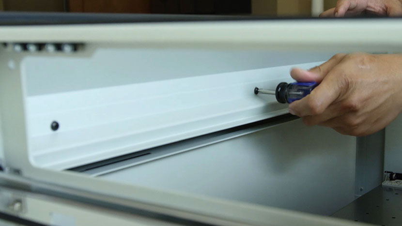
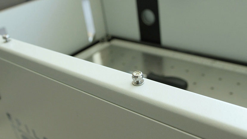
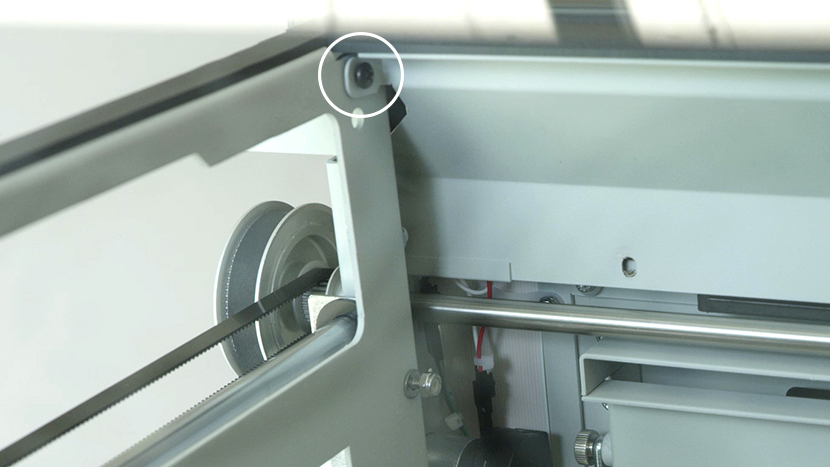
Remove the two screws at the top corners of the top panel. Then remove the top panel.

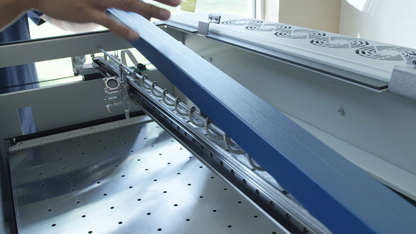
Removing one of the top corner screwsRemoving the top panel

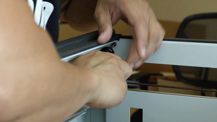
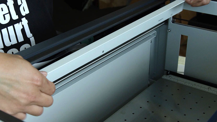
Loosen the four nuts using a socket wrench, then remove the bezel by sliding it out from under the screws, away from the machine.

The nuts holding down the bezelRemoving the bezel

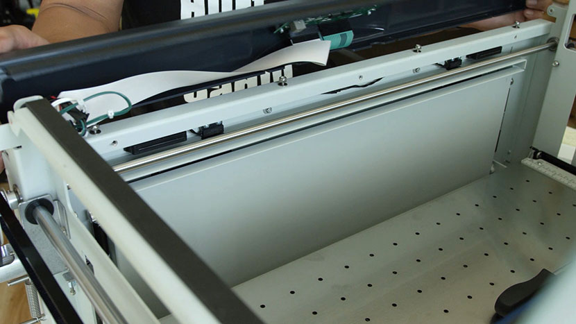
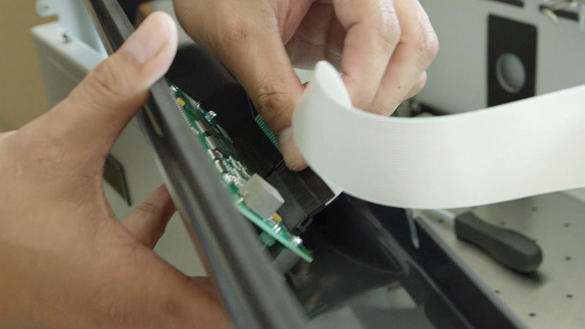
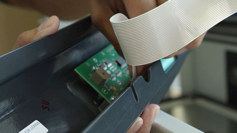
Unplug the flex cable from the keyboard by pinching the harness clip at the base.

Unplugging the flex cable

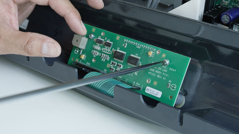
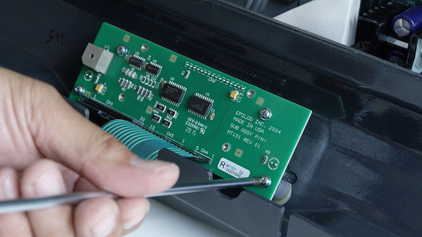
Remove the four screws from the PCB and remove the control panel plug. Set the PCB aside.

Removing the screws securing the PCB to the bezelUnplugging the control panel connector from the PCB

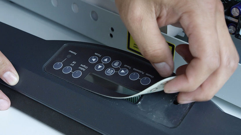
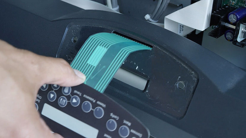
Peel the keypad off the front of the bezel.

Peeling the keypad off the front of the bezel

Install New Keypad

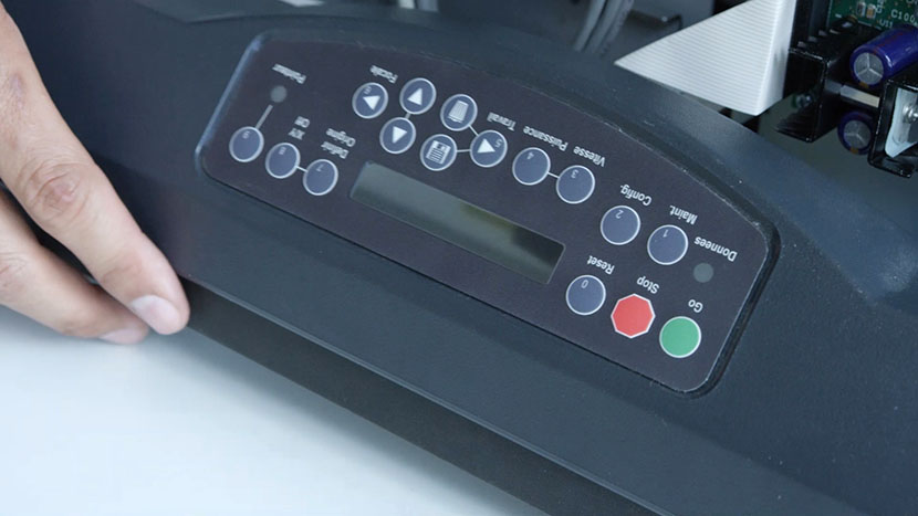
Install the new keypad by sliding the connector through the top bezel slot and pressing the keyboard’s adhesive back to the recess in the bezel.

Inserting the new keypad's connector through the bezelThe new keypad applied to the bezel recess

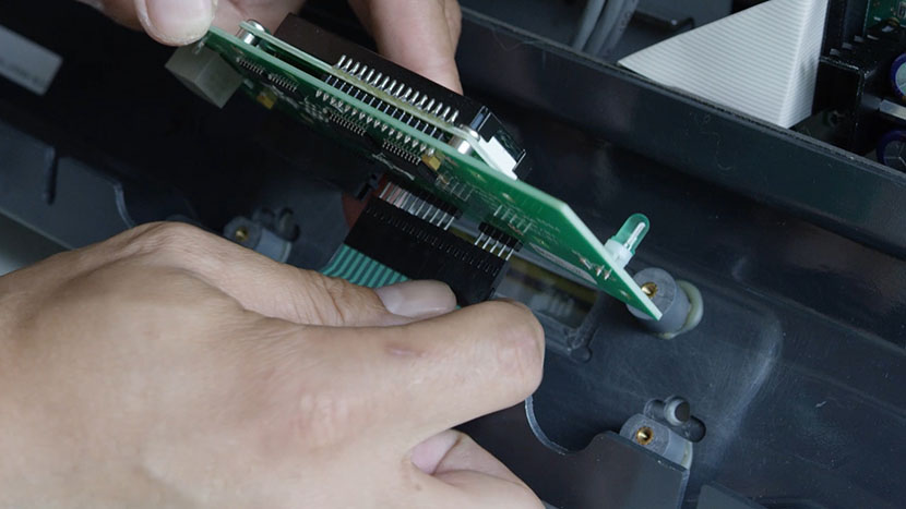
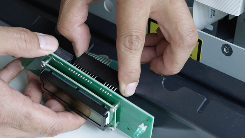
Plug the keypad into the PCB, then insert the PCB’s four screws.

Plugging the keypad into the PCBInserting the four PCB screws

Plug the flex cable into the PCB.

Plugging the flex cable into the PCB

Replace the bezel by sliding it under the front four nuts. Tighten the nuts slightly to hold the bezel in place.

The loosened nuts that will secure the bezelSliding the bezel back onto the machine

Reinstall four outer screws, making them hand-tight.

Inserting the two screws on the left side of the bezelInserting the two screws on the right side of the bezel

Install the top interior panel by loosely inserting the two top screws.

One of the top panel screws

Install the bottom panel by affixing it to the two bottom nuts. Insert the three center screws to secure both panels.

The bottom panel's nutThe three screws that secure the interior panels

Now ensure the back panels are secure by tightening the three center screws, the two top screws, and the two bottom nuts. Make them hand-tight and take care to not overtighten them.

Reinstall Side Panels

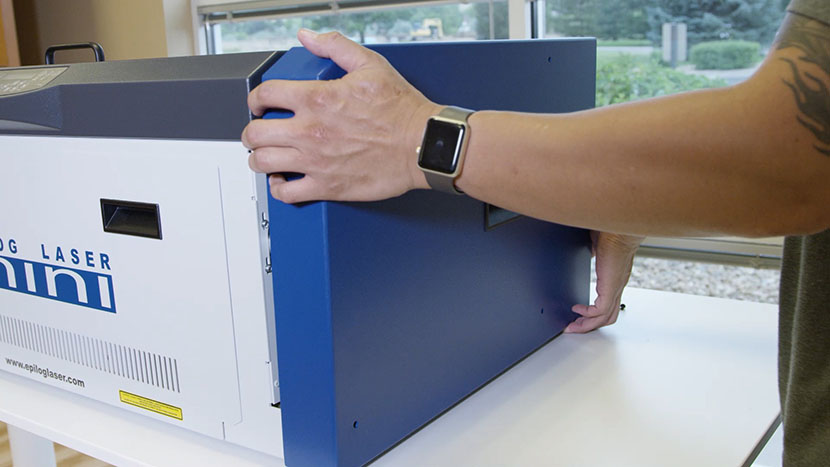
Replace the right side panel, inserting the four screws on the panel’s main face, as well as the two screws on the back.

Putting on the right side panel

Inserting the screws on the main face of the right side panelInserting the screws on the back of the right side panel

Replace the left side panel, inserting the four screws on the panel’s main face, as well as the two screws on the back.

Putting on the right side panel

Inserting the screws on the main face of the left side panelInserting the screws on the back of the left side panel

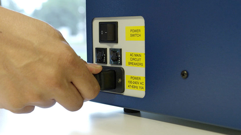
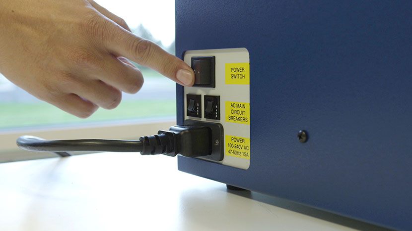
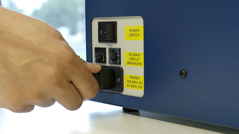
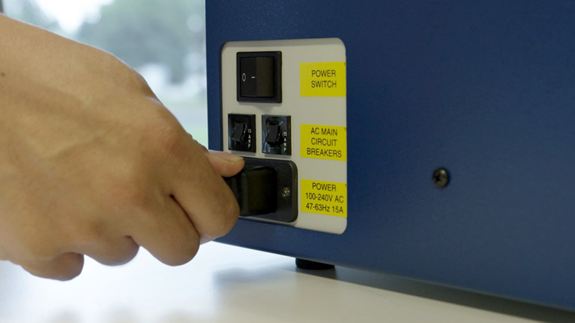
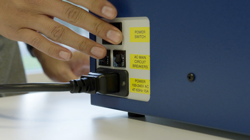
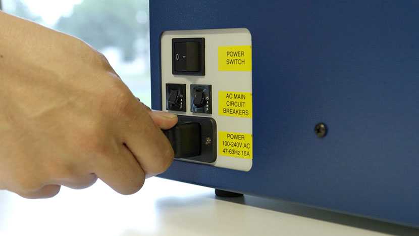
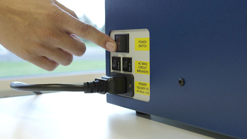
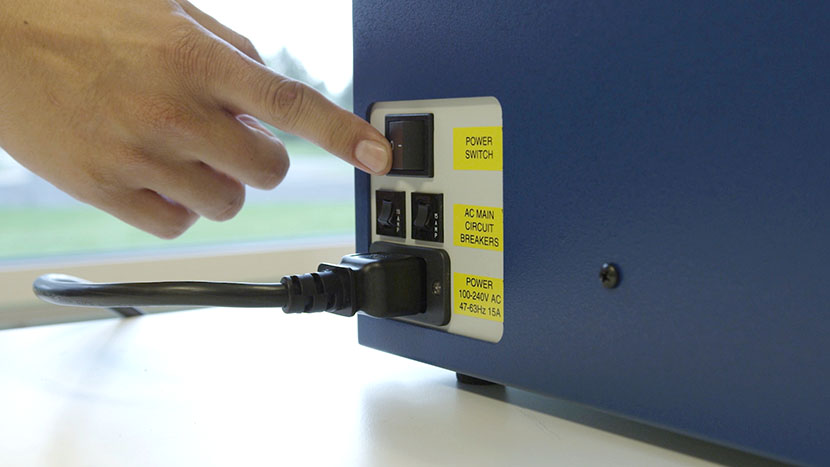
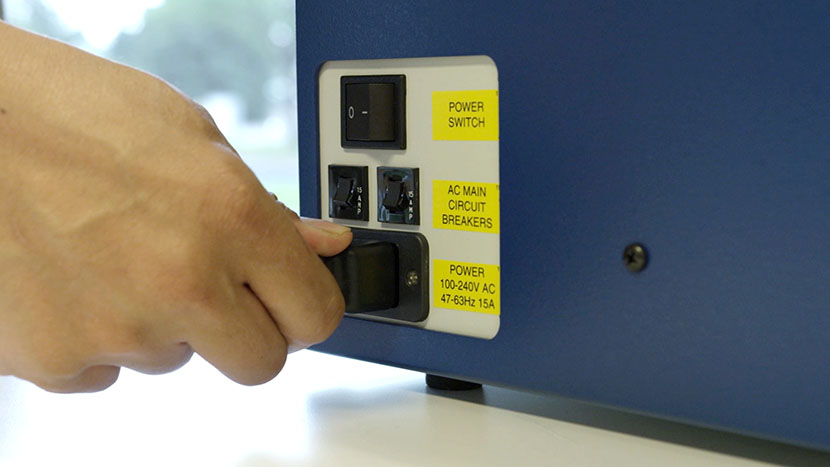
Plug the machine in and turn it on.

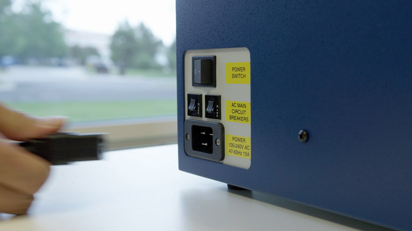
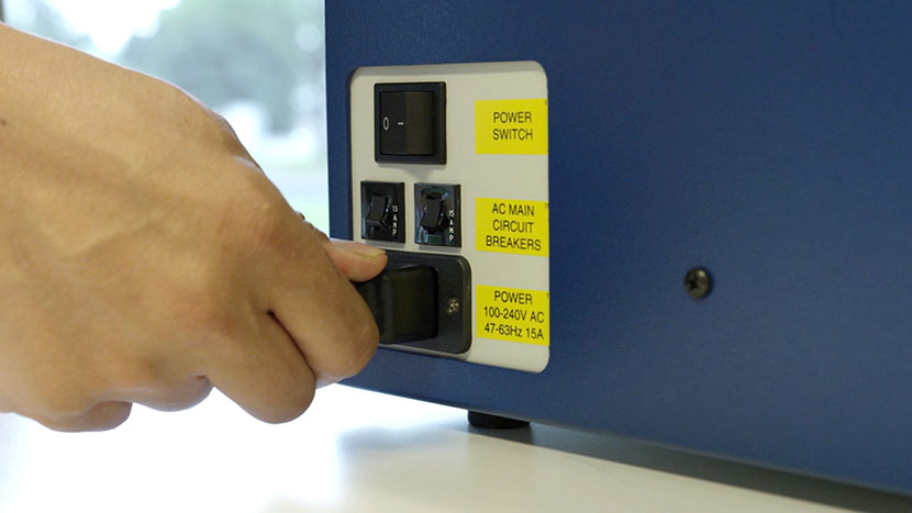
Plugging the power cord into the machine

Controller Board

Record Settings

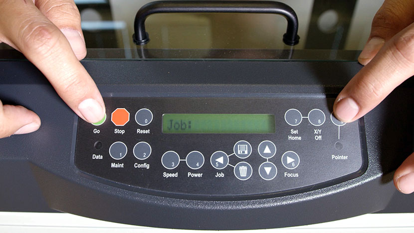
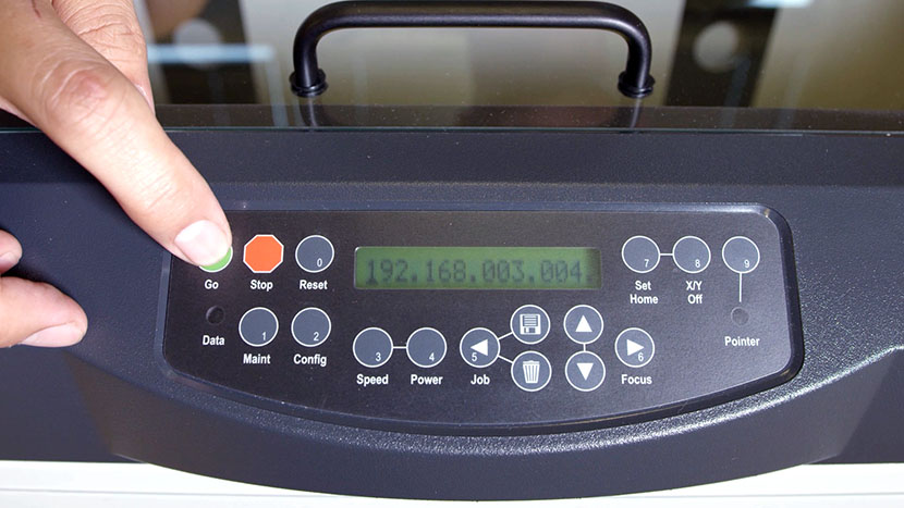
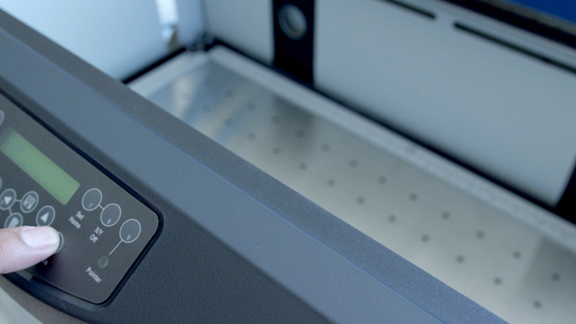
If your machine will boot up, we’ll start by writing down some settings that will save you time later. Press the Go and Pointer button at the same time to access the Function menu and cycle through the headings by pressing the Go button. Write down the Serial Number, IP Address, Subnet Mask and Gateway.

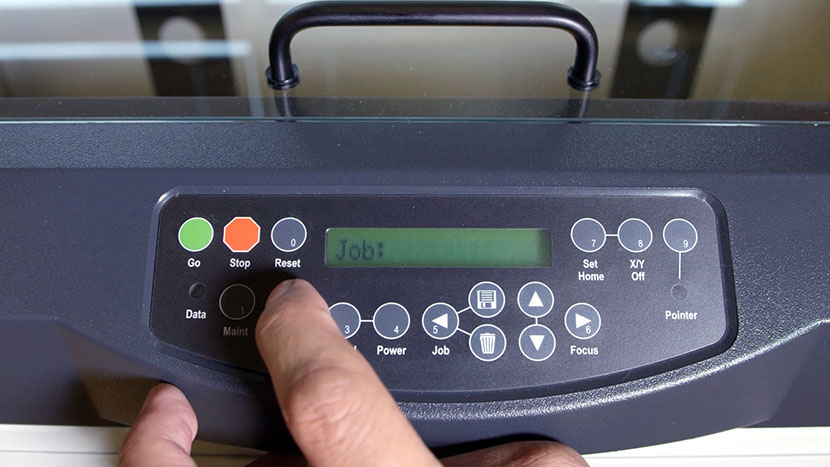
Pressing the Go and Pointer button on the control panel at the same time.Pressing the Go button on the control panel.

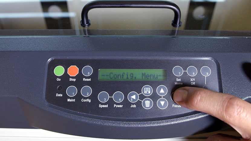
Next, press the Configuration button on the display panel and cycle through the menu by pressing the right arrow. Write down the X-Home, Y-Home, Laser Match, Stamp Match and System Unit.

Pressing the Config button on the control panel.Pressing the right arrow button on the control panel.

Remove Right Side Panel

Shut off the laser and remove the power cord from the machine.

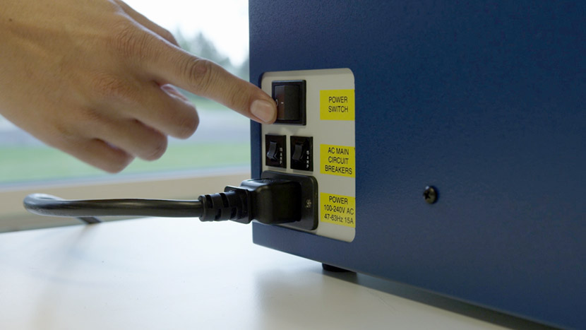
Flipping the power switch on the machine.

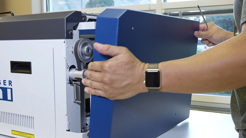
Remove the right side panel by removing the 6 screws, 4 located on the side of the machine, two located on the back of the machine.

Removing the screws on the right panel's main face.Removing the screws on the right panel's back face.

Pulling the right panel off of the chassis.

Equip Static Strap

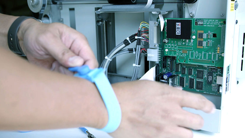
Put on the anti-static strap. Always wear the anti-static strap when handling the control board to avoid damaging the unit through static discharge. Clip the strap on to any metal part of the machine.

Putting the anti-static strap onto your wrist.Clipping a wrist-mounted static strap to the machine.

Remove Old Controller Board

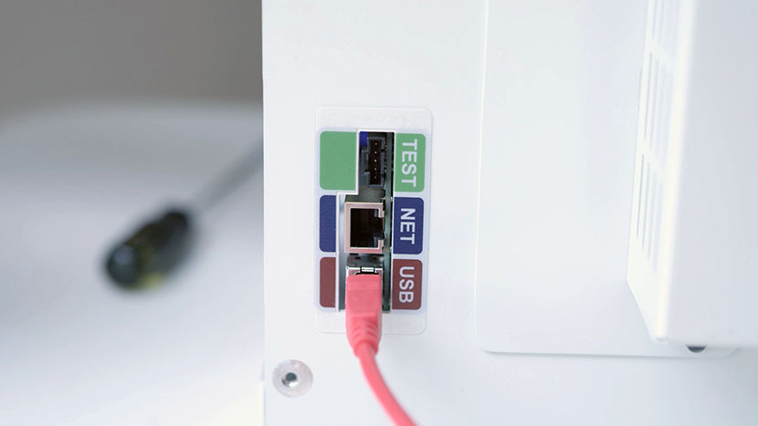
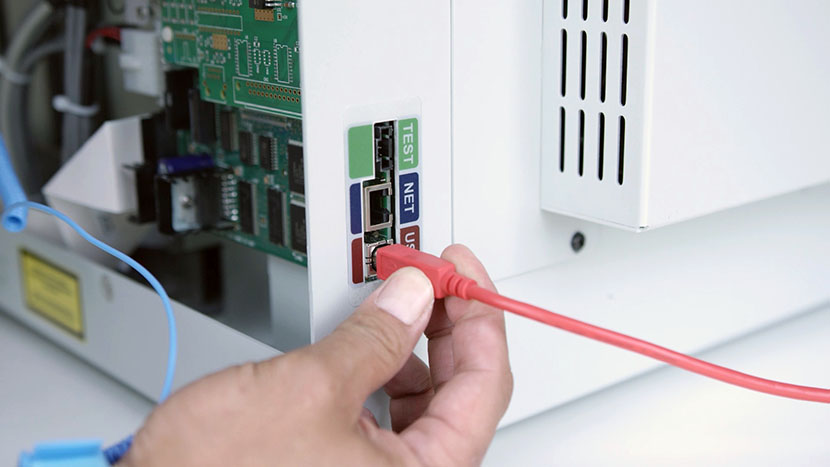
Depending on the type of connection you are using to print to the laser, you will need to either disconnect the Ethernet cable or USB cable from the back of the engraver where it plugs into the controller board.

Close up of the USB and Ethernet ports on the back of the machine.

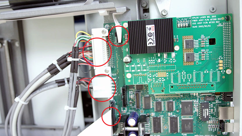
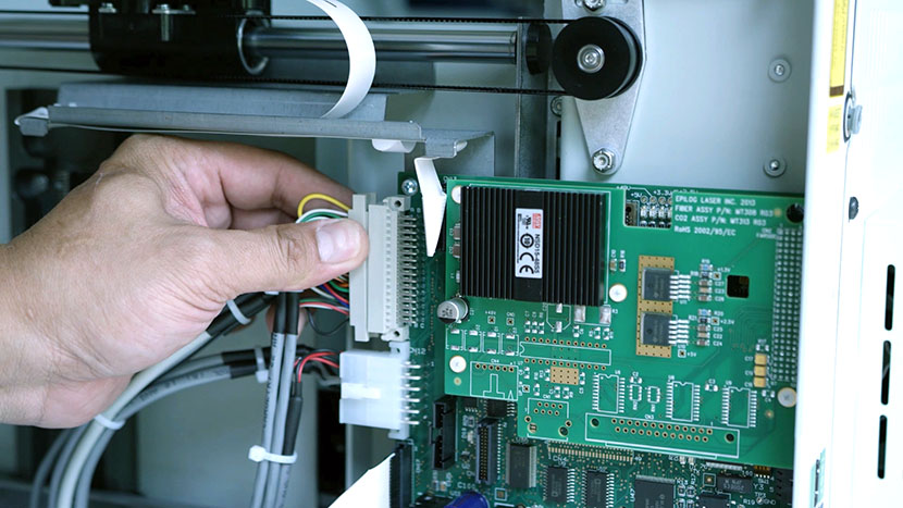
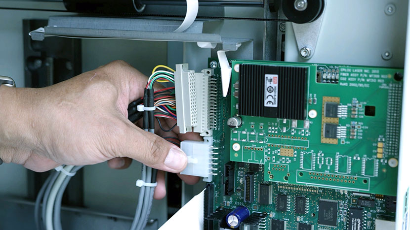
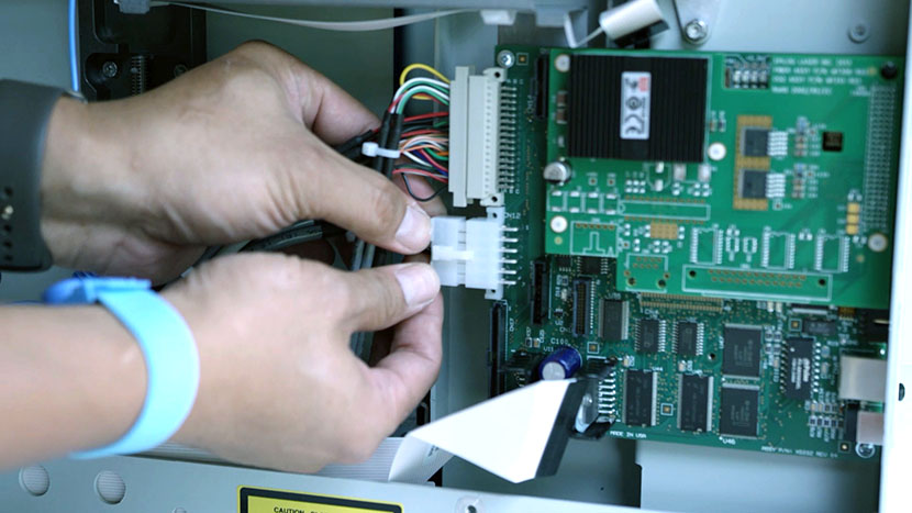
Locate the Controller Board on the right side of the machine towards the rear. Unplug the 4 connectors on the controller board mainly located along the left side if you are looking directly at it.

The controller board inside the machine, with the four connectors highlighted.

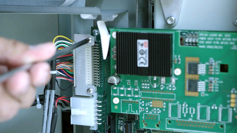
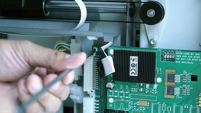
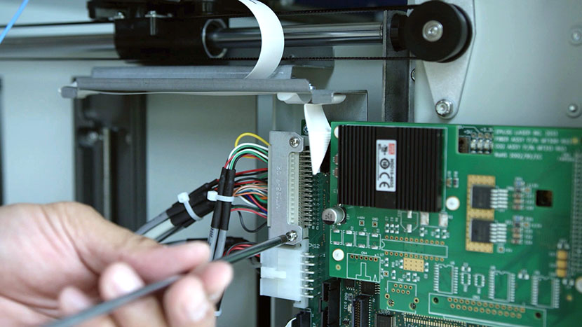
On newer machines, one of those 4 connectors will have a bracket with 2 Phillips head screws holding the connector in place to secure it to the board. If you have the newer machine, use a Phillips head screw driver to remove the 2 Philips head screws from the bracket so you can unplug the connector.

Removing the screws holding the top connector mounting bracket.

The older machine does not have that bracket, and only requires removing the light grey connector located on upper left side of the board.

Removing the controller board's top connector.Removing the controller board's middle connector.

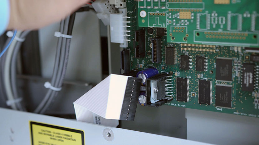
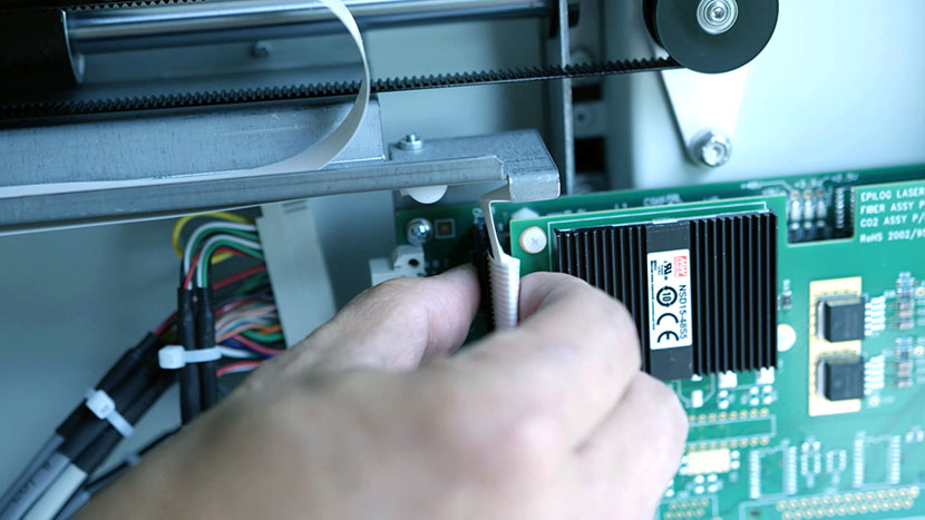
Removing the controller board's bottom ribbon connector.Removing the controller board's top ribbon connector.

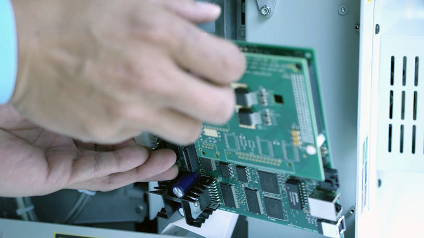
To remove the Controller Board, use the Phillips head screw driver to remove the 4 Philips head screws located on each corner of the board.

Unscrewing one of the four controller board mounting screws.Pulling the old controller board out of the machine.

Install New Controller Board

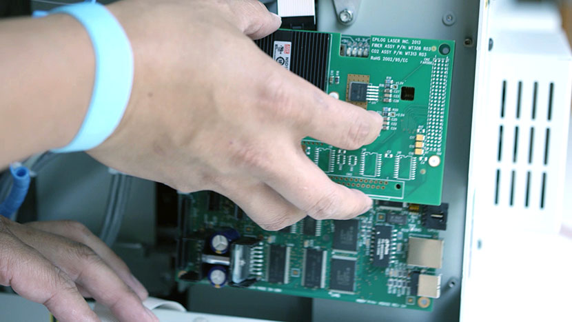
Install the new Controller Board, replacing all 4 Philips head screws to each corner of the board.

Putting the new controller board into position within the machine.Inserting the controller board mounting screws.

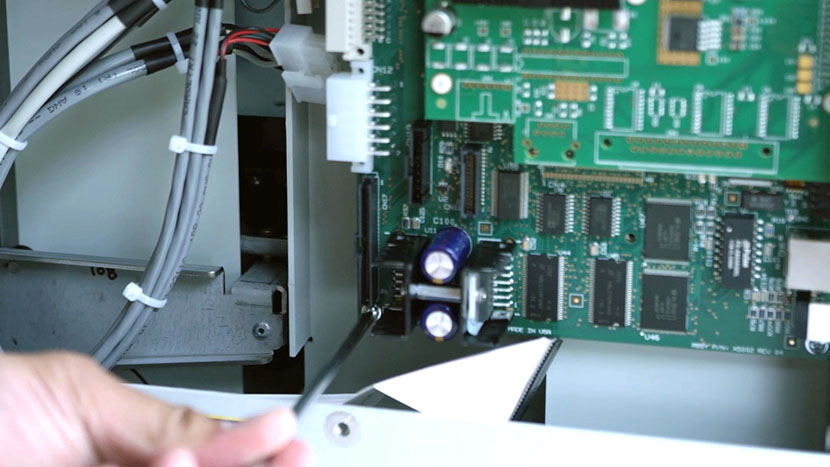
Reconnect all 4 connectors to the controller board. If you have a newer machine, tighten the 2 Philips head screws on the bracket of the last connector.

Plugging the four connectors back into the controller board.Screwing in the top connector mounting bracket.

Reconnect either the Ethernet cable or USB cable into the Controller Board, whichever you are using to connect to the laser.

Plugging the USB cord back into the back of the machine.

Reinstall Right Side Panel

Replace the right panel, tightening all 6 screws.

Putting on the right side panel.

Inserting the screws on the main face of the right side panel.Inserting the screws on the back of the right side panel.

Plug the machine in and turn it on.

Plugging the power cord into the machine.

Z-Motor / Table Motor Replacement

Adjust Table Position

Start by turning on the machine and then raise the table all the way to the top.

Shut off the laser and remove the power cord from the machine.

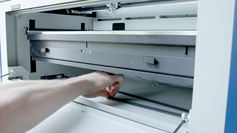
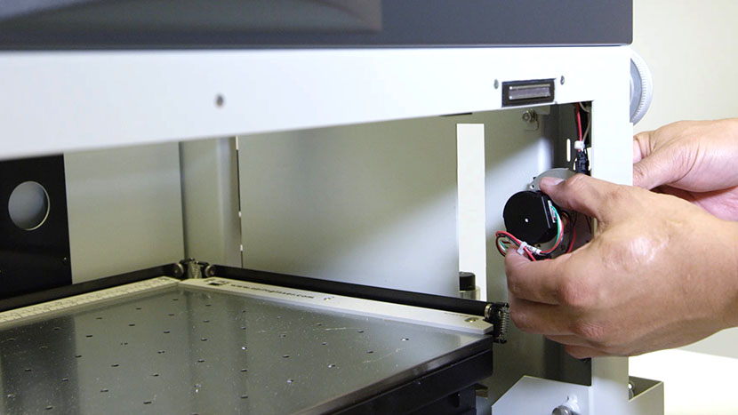
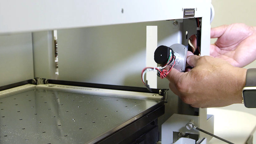
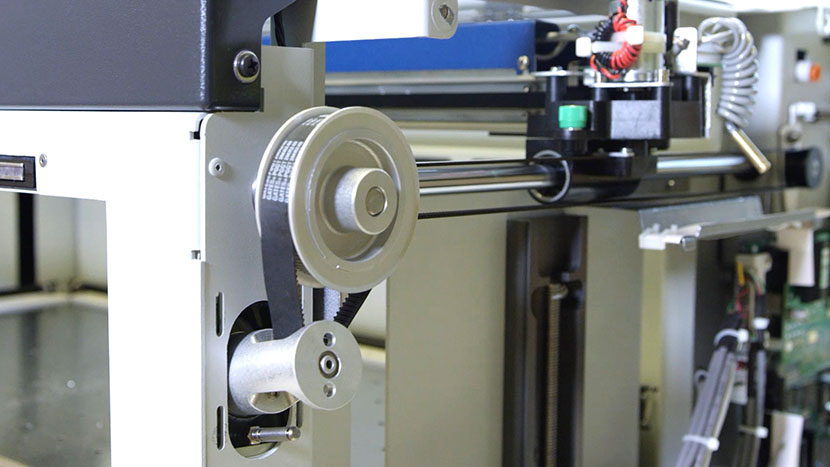
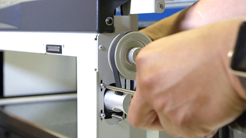
To manually adjust your laser machine’s vertical table position, pull on the belt located underneath the table to raise or lower it to the proper height.

Remove Panel

Remove the right side panel by removing the 6 screws, 4 located on the side of the machine, two located on the back of the machine.

Remove Old Motor

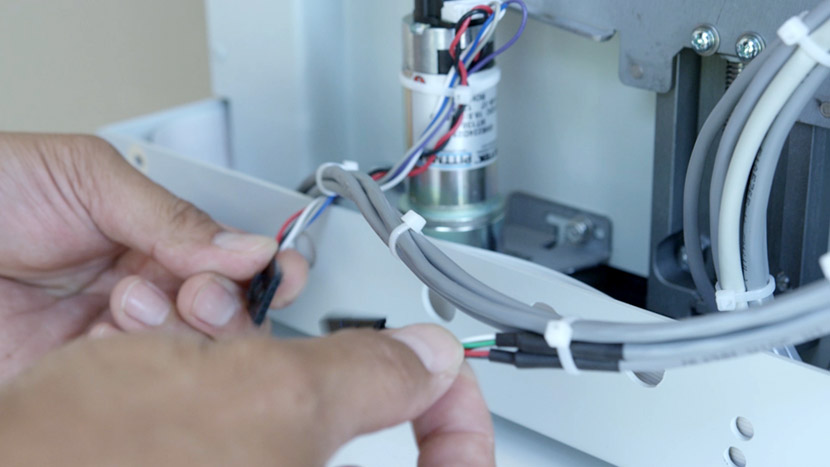
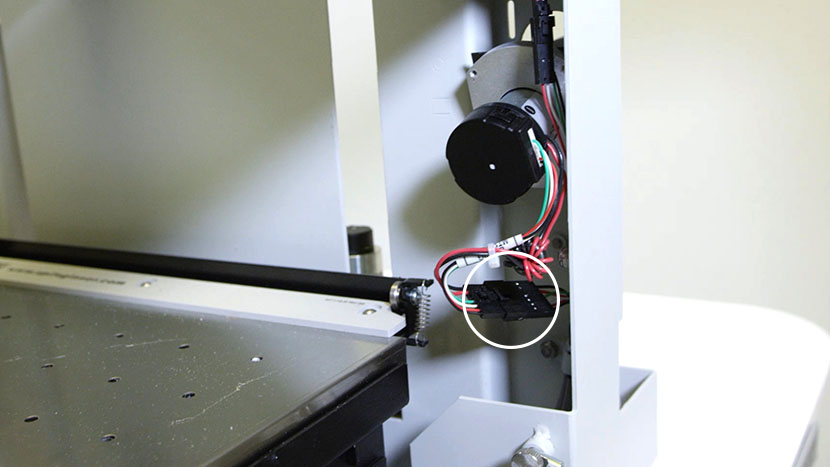
Disconnect the electrical connector.

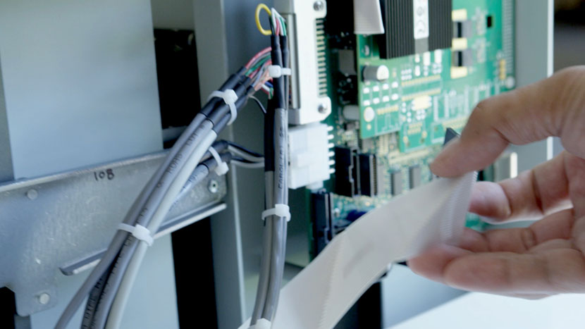
Disconnect the white ribbon cable connected to the control board.

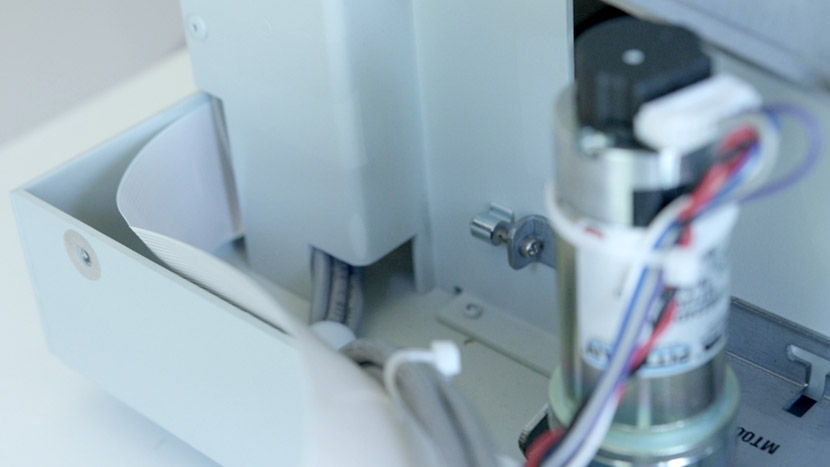
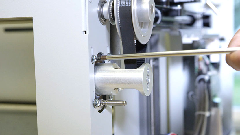
A 3/32 Hexagonal screw controls the tightness of the belt, which needs to be at a certain tightness in order for the motor to work properly.

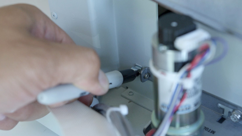
Therefore, before removing the bracket, use a sharpie marker to color the visible thread between the bracket and the fixed nut. Be sure to color the edge of the thread and the fixed nut.

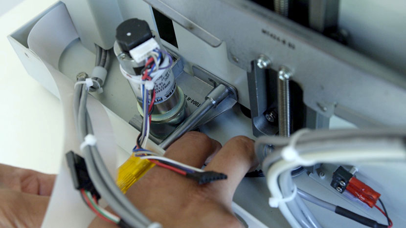
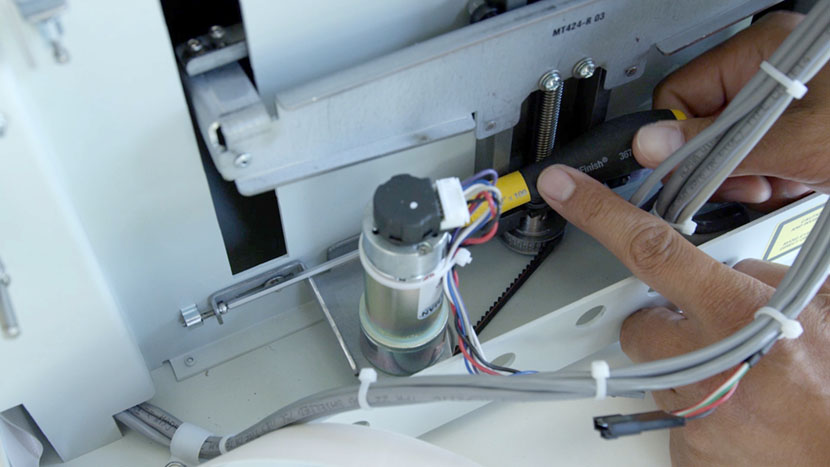
With a long 5/16 nut driver, unscrew the two nuts on the motor bracket, pulling gently against the z-belt to keep it tight so it doesn’t loosen and come off the other pulley.

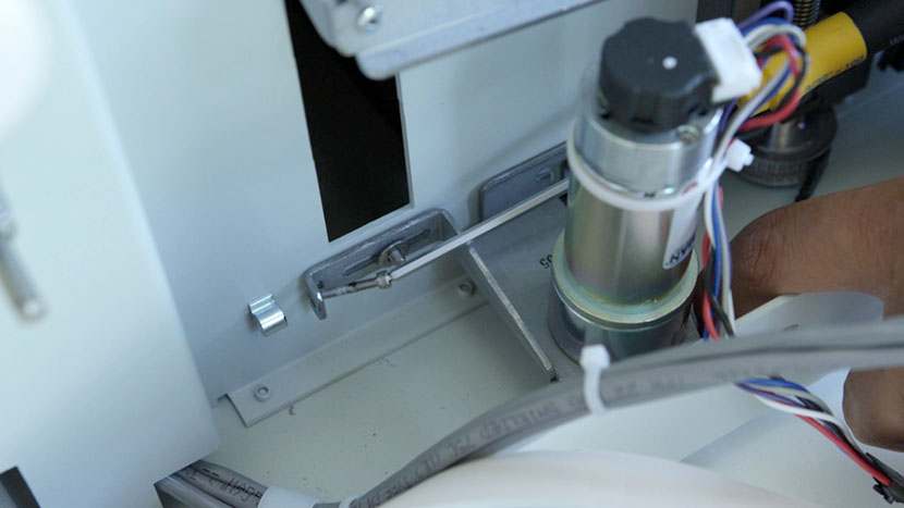
Unscrew the 3/32 hexagonal screw.

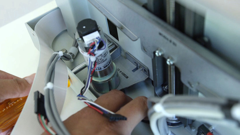
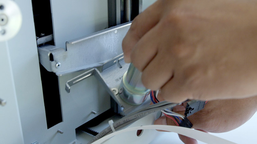
Remove the Z-motor and bracket.

Install New Motor

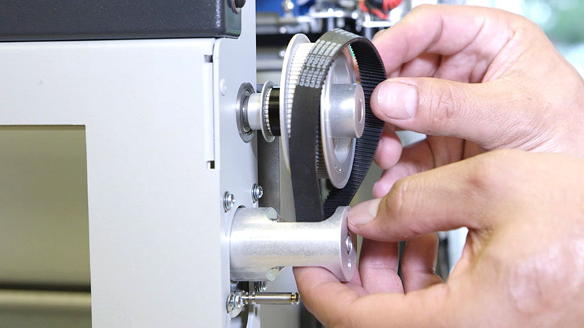
Insert the new z-motor assembly, wrapping the z-belt between the silver pulley and the bracket, and positioning the bracket on the fixed screws.

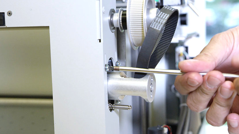
Insert the hexagonal tensioning screw.

Put a washer and nut onto each fixed screw, but do not tighten them.

Tighten the hexagonal tensioning screw until the edge of the black mark is at the edge of the fixed nut. The mark should be in the exact same spot as it was before the screw was taken out.

Tighten the nuts on the fixed screws

Reconnect the motor lead.

Reconnect the white ribbon cable to the control board.

Reinstall Panel

Replace the right side panel, tightening all 6 screws.

Plug the machine in and turn it on.

Y-Motor Replacement

Remove Right Panel

Remove the right side panel by removing the 6 screws, 4 located on the side of the machine, two located on the back of the machine.

Removing the screws on the right panel's main face.Removing the screws on the right panel's back face.

Pulling the right panel off of the chassis.

Remove Old Y-Motor

Open the front access door.

Locate the Y-Motor on the right hand-side of the machine.

Looking at the Y-Motor from the interior of the machine.Looking at the Y-Motor from the exterior of the machine.

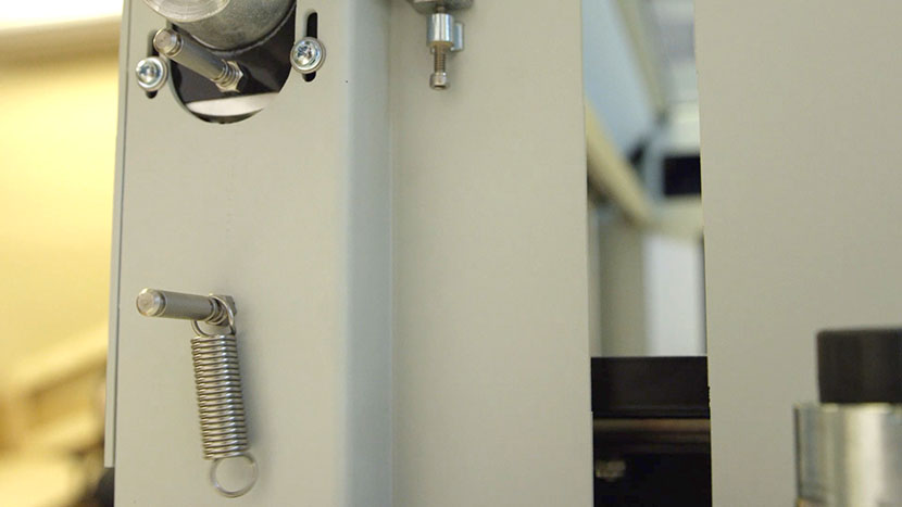
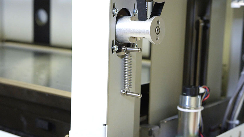
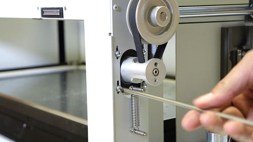
Remove the spring holding the motor. Let the spring hang from the bottom peg.

The Y-Motor tension spring hanging from the bottom peg.

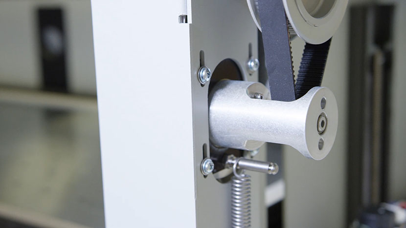
Loosen the four screws holding the motor bracket. With the four screws loosened, slip the Y-Motor belt around and off the large Y-Axis drive pulley.

Loosening the Y-Motor mounting screws.Slipping the Y-Motor belt off the Y-Axis drive pulley.

Now remove the four Philips head screws completely.

Removing the Y-Motor mounting screws.

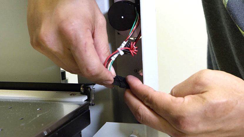
Disconnect the motor lead. This connector is in the inside of the machine.

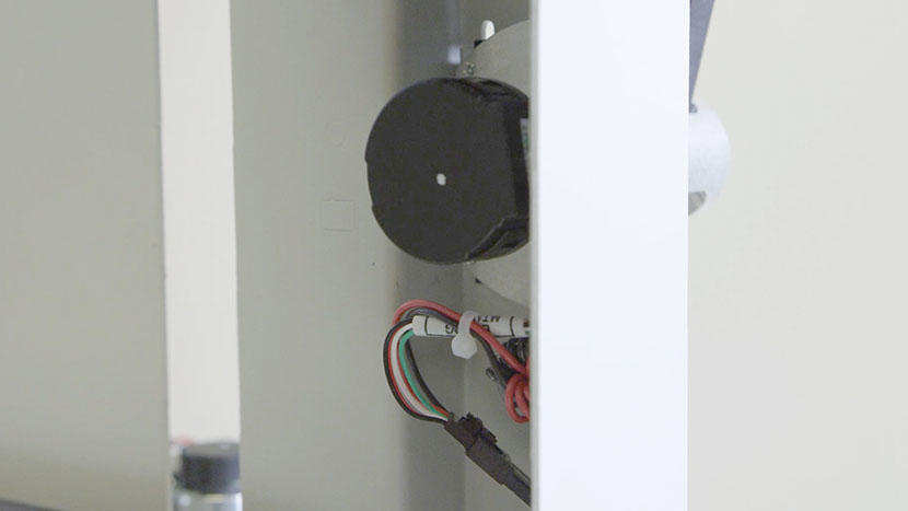
The Y-Motor electrical connection.

Pull the entire assembly out.

Pulling the Y-Motor out of the machine.

Install New Y-Motor

Insert the new motor assembly into position with the belt pointing up, while minding the wires surrounding the motor.

Putting the new motor assembly into place from the interior of the machine.

Loop the Y-Motor belt over the large Y-Axis drive pulley.

The motor with its belt looped around hte Y-Axis drive pulley.

Start threading the four Phillips head screws but do not tighten them down all the way.

Inserting one of the motor mounting screws.

Place the spring on the upper peg and on the farthest back notch.

The Y-Motor tension spring affixed to the two pegs.

Tighten the four screws.

Tightening the four Y-Motor mounting screws.

Reconnect the motor lead.

Reconnecting the Y-Motor wires.

Reinstall Right Panel

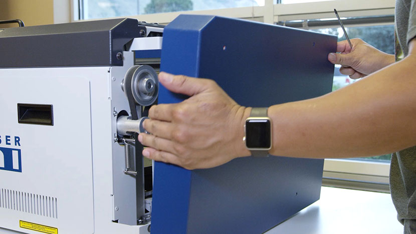
Replace the right side panel.

Putting on the right side panel.

Inserting the screws on the main face of the right side panel.Inserting the screws on the back of the right side panel.

Close the front access door.

Plug the machine in and turn it on.

Plugging the power cord into the machine.

Wood Keychain

Setting Up Your Page

We’ll start by creating a new file in CorelDRAW.
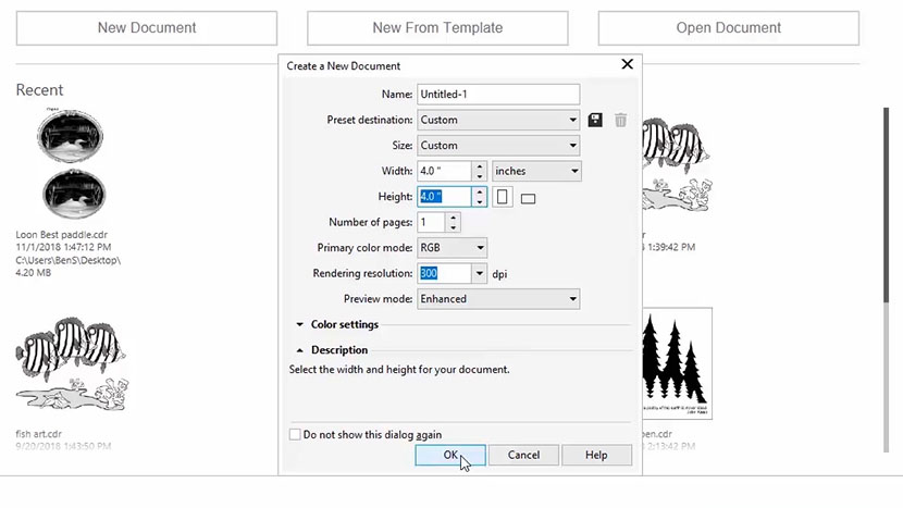
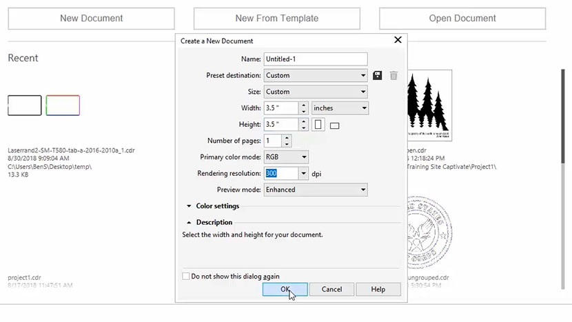
The New Document dialog in CorelDRAW.

Click on the Get Started option on your Welcome screen, then click the New Document button. You can also use the shortcut keys Ctrl + N for opening a new document.

Now enter your page size. Enter 4” for the page width and 4” for the page height, then click OK.

Creating a Keychain Jig

For this project we’ll be engraving a wooden keychain, but first let’s create a cardboard jig to hold our keychain in place and reduce our setup time in the future.
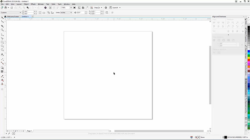
A new document in CorelDRAW.

To create a jig we need to create a hole the same size as the keychain so we can accurately place the keychain within the jig. Start by measuring the width of the keychain you received in your Training Suite packet. Use a set of calipers or a ruler to measure the keychain. The keychain should be 1.6”. We’ll use this later to set the diameter for the jig circle.

Now we’re going to draw a circle in CorelDRAW. Select the Ellipse tool in the toolbox on the left. While holding down the Ctrl key, click and drag across the page to create a circle. The size won’t matter as we are going to manually key in the width (diameter) for our jig circle.
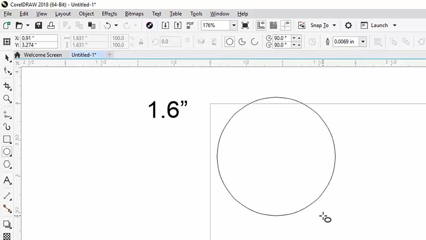
Creating a 1.6 in. diameter circle in CorelDRAW.

Once you’ve drawn your circle, click on the Lock Ratio button in the Properties bar at the top of the screen. Turning on the Lock Ratio option will make sure that the width and height of the circle are the same when we change the width in the following step.
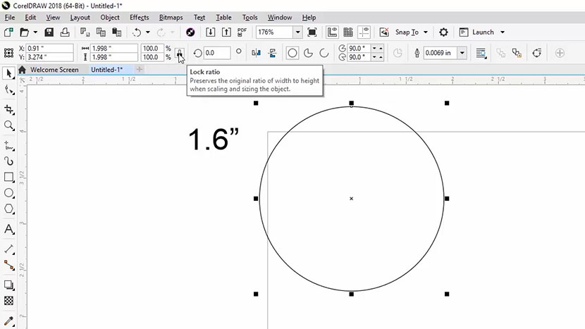
The Lock Ratio button in CorelDRAW.

Now enter the Width (diameter) of the keychain you measured earlier into the Object Size box at the top of the screen. We’ll enter 1.6” here, then press Enter key.
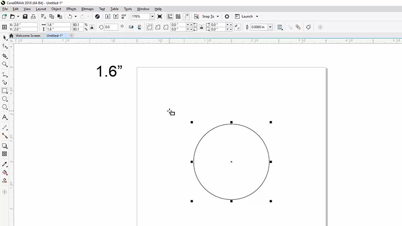
The Object Size box at the top of the screen.

Now, we need a spot in the jig for the eyelet and ring to rest. Select the rectangle tool in the toolbox. We’ll need the rectangle to start about 0.25” above the circle and be about 0.25” wide.

Click and drag from above the circle down into the circle to create the cutout for the eyelet and ring.
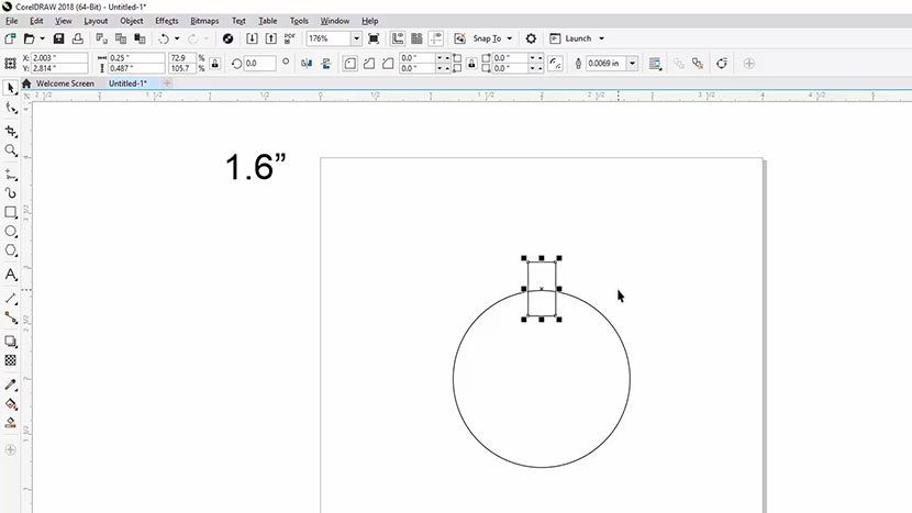
Creating a rectangle in the jig design for the keychain eyelet.

If you prefer you can align the rectangle to the center of the page horizontally by selecting Object > Align and Distribute > Center to Page Horizontally.
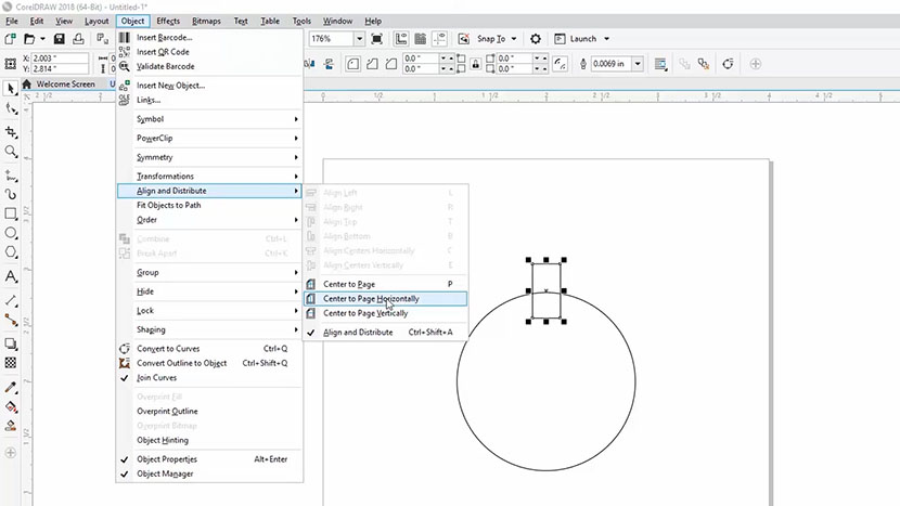
The Object > Align and Distribute menu in CorelDRAW.” title=”With the rectangle selected, choose Center to Page Horizontally from the Object menu.” /></p>
<p>Now we’ll convert these lines to cut lines. With the Selection Tool, click and drag a rectangle around both shapes to select the them. Since we want to cut out the jig, not engrave it, we need to change the outline thickness of the selected shapes to Hairline or less than .004”. With the shapes selected, click on the Outline Width drop-down menu in the Properties bar at the top of the screen, and select Hairline from the menu.</p>
<p><img decoding=

Printing to the Laser (Jig Cutting)

Now that we’ve completed the outline for our jig, we now want to print this file to the laser. Select File, then Print from the dropdown menu at the top of the screen. Select your Mini/Helix laser from the printer options, and then click the Preferences button.
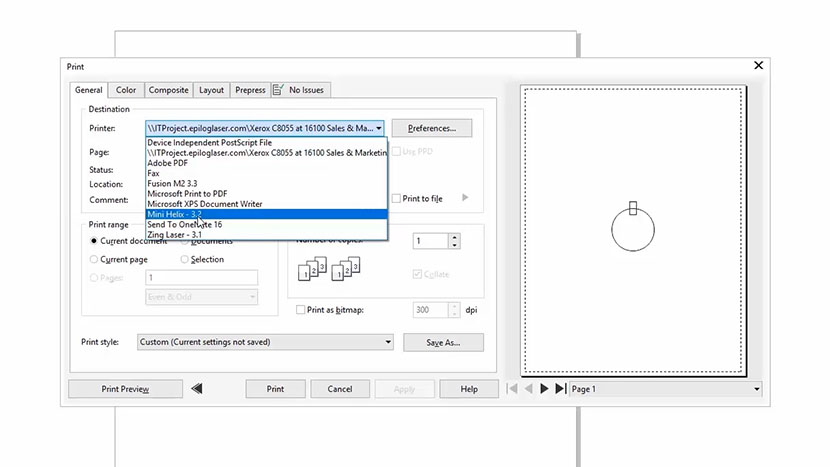
Selecting the Mini/Helix from the Print dialog in CorelDRAW.

In the Laser Dashboard:

  • Set the Job Type to Vector.
  • Change the Piece Size to 4” x 4”.
  • Set the Speed to 20%, Power to 100%, and Frequency to 500. (Refer to your laser manual for the suggested speed, power, and frequency settings for cutting cardboard with your wattage of laser.)
  • Make sure Send to Laser is checked.
  • Uncheck Send to Manager.

Then click the OK button.
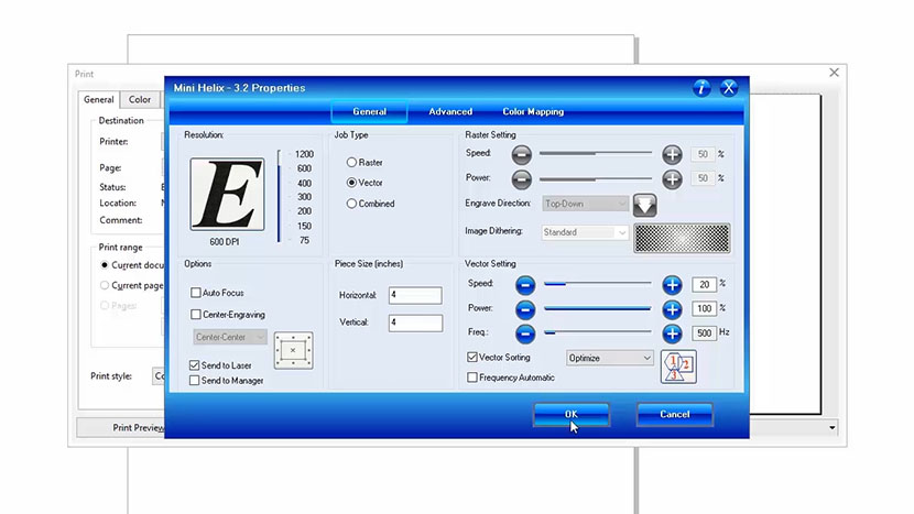
The Epilog Mini/Helix print driver.

The print preview should now look like our Corel file.

Finally, click Print to send the job to the laser!
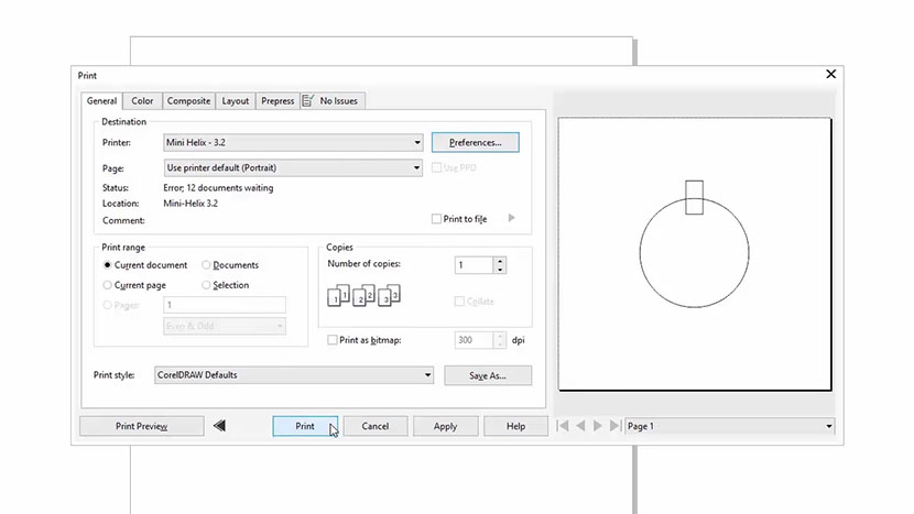
The CorelDRAW print dialog.

Cutting the Jig at the Laser

At the laser, position your piece of cardboard in the Home Position at the top-left corner of the work area.
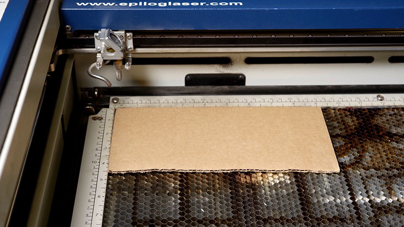
A piece of cardboard in the top-left corner of the Mini/Helix vector cutting grid.

Then press the Focus button on the keypad to bring the X-Axis out over the workpiece. Hang your manual focus gauge on the optics assembly. Press the Up arrow on the keypad to move the table up and bring the material into focus. Once you’re focused, remove the manual focus gauge and press the Reset button. Now we’re ready to start the job.
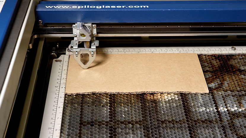
The manual focus gauge above the cardboard.

Now we’re ready to start the job. Press the Go button on the keypad to begin cutting your jig for the keychain engraving.
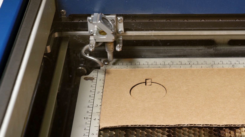
The piece of cardboard with the keychain jig shape cut out of it.

Importing Graphics

With the jig for the keychain cut, now it’s time to set up our graphic for the keychain. Keep your jig design open in CorelDRAW, as we are going to build from it and use the jig lines as a design template.

Now we’re going to import a graphic, resize it, and center the graphic to the jig circle for engraving on the wooden keychain. We’ll use a sea turtle graphic (sea-turtle.eps ) for this example, but you can use any graphic you prefer.

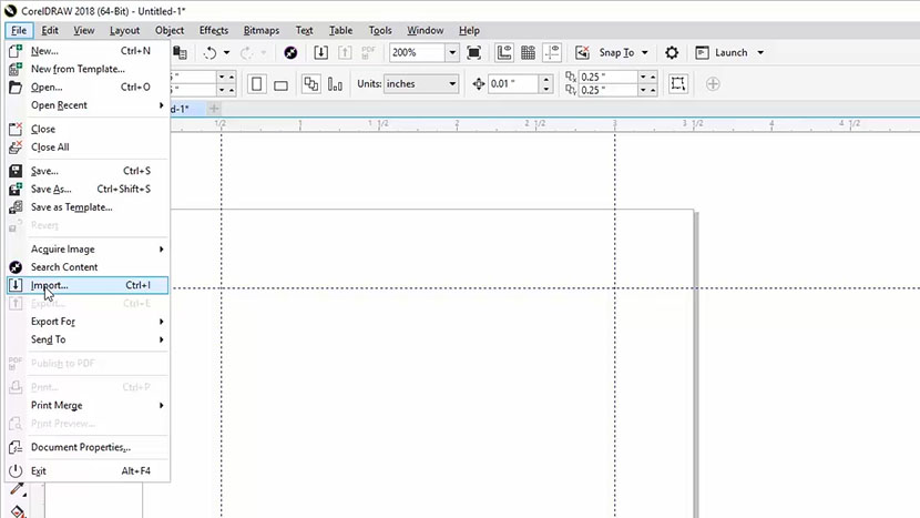
To import the file, select “File”, then “Import” from the drop-down menus at the top of the screen.
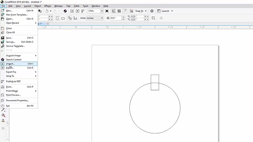
The File > Import option in CorelDRAW.” title=”Import a file by selecting File > Import from the menu at the top of the screen.” /></p>
<p>Navigate to the file you’d like to Import (sea-turtle.eps for this example project), then select the file and click the Import button.</p>
<p><img decoding=

When the Import EPS options pop up you can leave the defaults as they are. Press the OK button to continue.
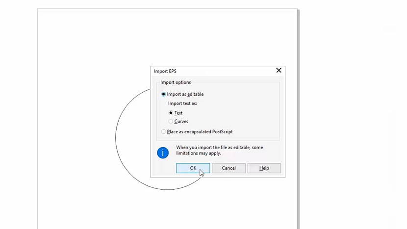
The Import EPS dialog in CorelDRAW.

Now, click anywhere on the page to place the graphic in the work area.
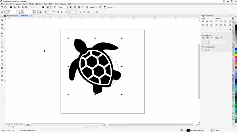
The imported graphic on the page.

Aligning and Resizing the Graphic

Now we need to align our turtle to the center of the circle and resize it to fit within the bounds.

Make sure the object is still selected, then click Object from the drop-down menu at the top of the screen, then Align and Distribute, then Center to Page. You can also use the shortcut option of pressing the letter ‘P’ on your keyboard to center the image to your page.
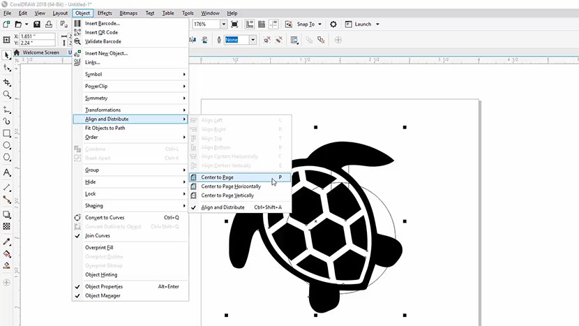
The Object > Align and Distribute drop-down menu in CorelDRAW.” title=”Center the graphic by selecting it, then choosing Center to Page.” /></p>
<p>Now we’ll resize the turtle to fit within the bounds of our jig circle and to account for the bevel on the edge of the wooden keychain. To resize the graphic, we’ll click and drag on the top right resizing handle to resize the image and make it smaller. With the bevel on the wooden keychain, we have about 1” of space to engraving within.</p>
<p>By clicking on the top-right sizing handle, then holding the Shift key and dragging toward the center of the image, we can keep the proportions of the image the same as we scale the image down.</p>
<p>Click and drag the sizing handle, while holding the Shift key, until the turtle is small enough to fit inside of the circle.</p>
<p><img decoding=

You’ll notice we have a little extra space to the bottom right of the turtle, so we’re going to click and drag the turtle down to the right a bit to visually center the turtle to the circle.
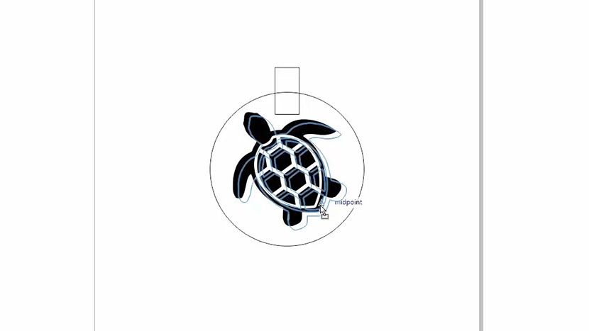
Dragging the graphic a little to the bottom right.

Printing to the Laser (Front Engraving)

With the graphic ready to go and still selected, we’re ready to print the graphic to the laser.

Select File, then Print from the dropdown menu, or press Ctrl + P on your keyboard.

Select your laser from the printer options.
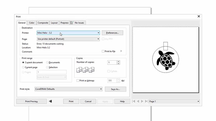
Selecting the Fusion from the Print dialog in CorelDRAW.

Under Print Range, click Selection as the option. This setting will print only the graphic you had selected to the laser, and not the jig outline we are using as a template.
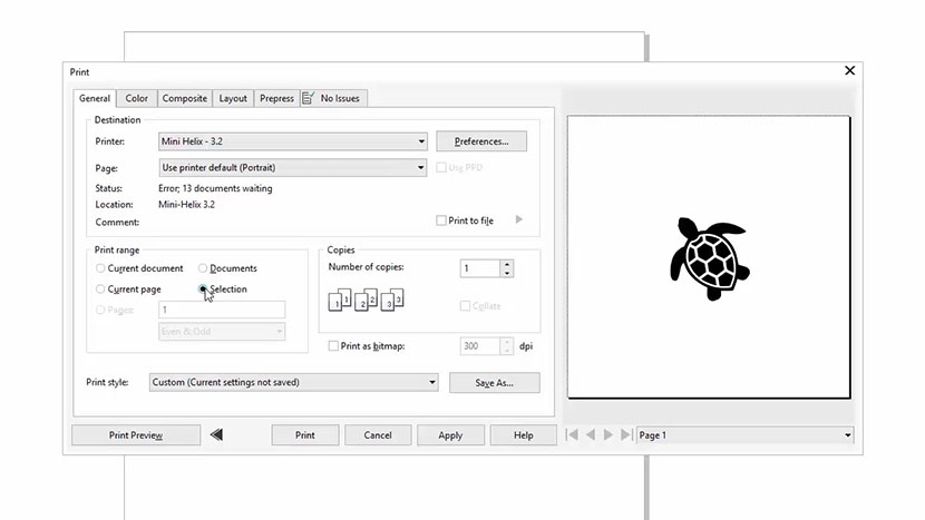
Setting the Print range to Selection in the CorelDRAW Print dialog.

Then click the Preferences button.

In the Laser Dashboard:

  • Set your Resolution to 600 dpi
  • Select Raster from the Job Type options. (We’ll use Raster since we’re only engraving this file, not cutting.)
  • Set the Speed to 60% and Power to 100%. (Refer to your laser manual for the suggested speed, power, and frequency settings for cutting cardboard with your wattage of laser.)
  • Select Bottom-Up for the Engraving Direction.
  • Select Stucki as the Image Dithering pattern. (The Stucki setting will randomize the dot pattern in the graphic and give us a consistent look to our wood engraving.)
  • Set the piece size to match your page size. Set the horizontal and vertical size to 4.00 inches.
  • Make sure Send to Laser is checked.
  • Uncheck Send to Manager.

Then click the OK button.
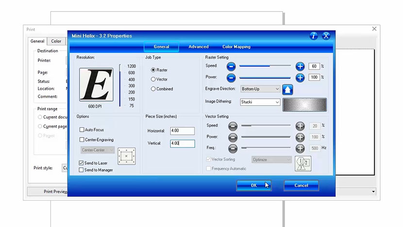
The Epilog Fusion print driver.

The print preview should now look like our Corel file.

Finally, click Print to send the job to the laser!
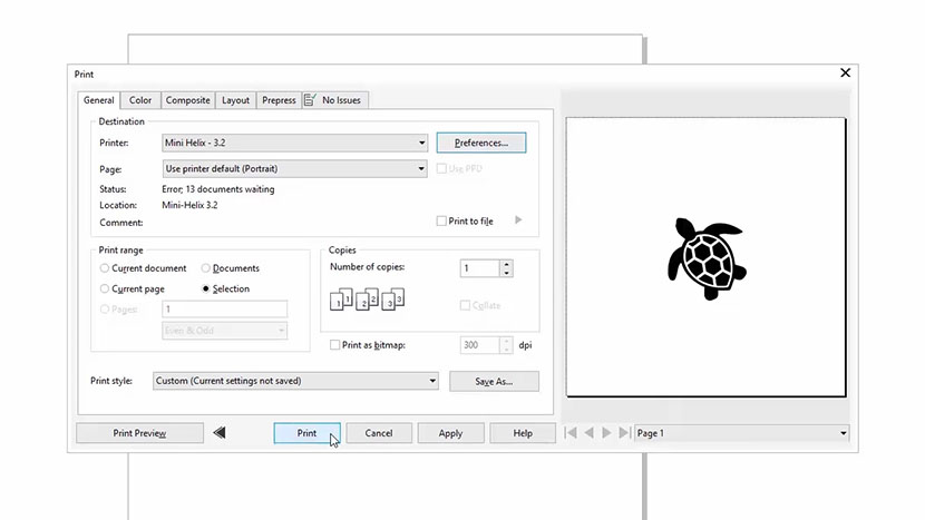
The CorelDRAW print dialog.

At the Laser (Front Engraving)

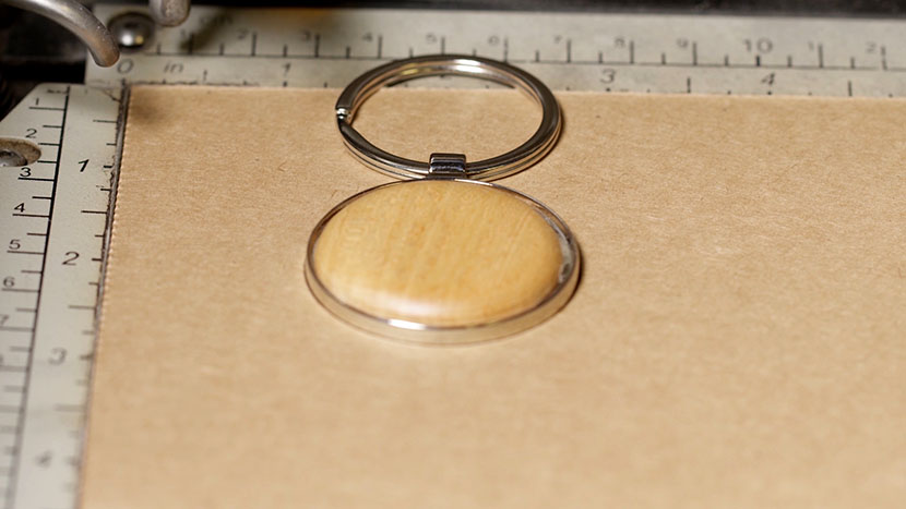
At the laser, we’ll place the keychain into our jig located in the top-left corner of our work area.

The keychain in the cardboard jig inside the Fusion.

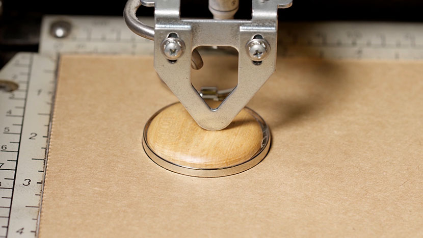
Then press the Focus button on the keypad to bring the X-Axis out over the workpiece. Hang your manual focus gauge on the optics assembly. Press the Up arrow on the keypad to move the table up and bring the keychain into focus. Once you’re focused, remove the manual focus gauge and press the Reset button. Now we’re ready to start the job.
The manual focus gauge above the keychain.

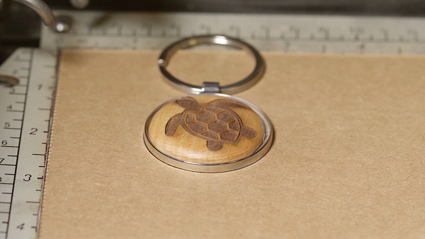
Now we’re ready to start the job. Press the Go button on the keypad to begin your wood keychain engraving job.
The graphic engraved onto the keychain.

Engraving the Backside with a Name

There are great time-saving advantages to using jigs when you need to engrave multiple items, or need to engrave on the backside of an item.

Let’s go ahead and engraving the backside of our keychain with a name to personalize the keychain for someone.

Flip the keychain over in the jig to get started.
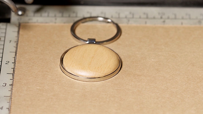
The keychain flipped over in the jig so the un-engraved side is facing up.

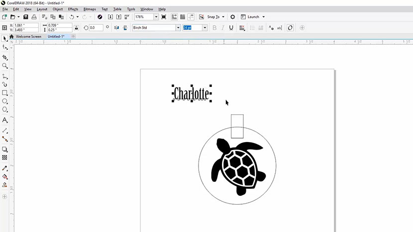
Back in CorelDRAW, we’re going to use the Text tool to add a name to our keychain. Select the text tool from the Toolbox options on the left side of your screen, and click anywhere on the page. Type out the name you would like to add to the keychain, and select the typeface you’d like to use for the name.
A name typed out using the Text tool in CorelDRAW.

We’re going to use the name Charlotte in Birch Std (Standard) for our example.
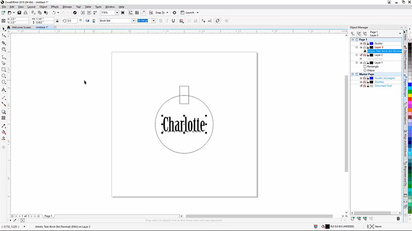
The name centered a resized to fit within the jig circle.

Once you’re finished typing out the name and selecting the typeface, click and drag the turtle outside of the page bounds, because we don’t want the turtle to be included in our next engraving.

Then press the ‘P’ shortcut key on your keyboard to center the name to the page and the jig bounds.

If you need to, resize the name to better fit it to the keychain’s engravable area. Remember to hold down the Shift key while resizing to keep the proportions of the text the same as you resize it.

Printing to the Laser (Back Engraving)

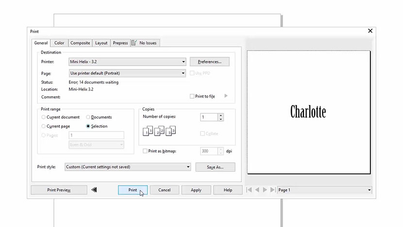
Since we’ve already engraved one side of the keychain, the engraving settings we used from the previous turtle engraving job will be saved in the Print Driver Dashboard settings. All we need to do now is hold Ctrl, then press ‘P’ on the keyboard, or you can click File, then Print from the menus at the top of the screen to print the file to the laser.
The name being printed from the CorelDRAW print driver.

Make sure the preview only shows the text you’ve selected to print, then click the Print button.

At the Laser (Back Engraving)

We’ve already flipped our keychain over to engrave the backside, and the laser’s focus is already set.

Simply press the Go button on the laser to engrave the name.
The final keychain with the name engraved.

And then you’re done!
Glass Coaster

Setting Up Your Page

We’ll start by creating a new file in CorelDRAW.

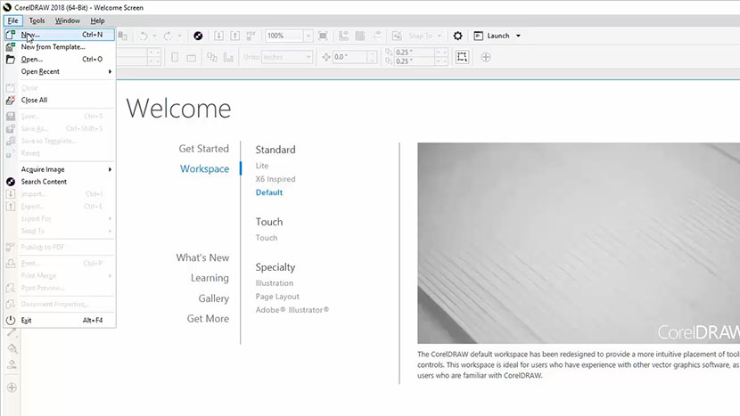
Click on the Get Started option on your Welcome screen, then click the New Document button. You can also use the shortcut keys, Ctrl + N, for opening a new document.

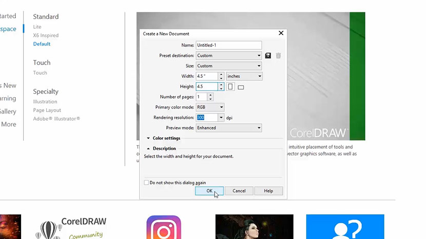
Now enter your page size. Enter 3.5” for the page width and 3.5” for the page height, then click OK.

Adding Guides for Your Engraving Area

The glass coaster you received with your laser system includes four rubber feet on the bottom of the coaster ½” in from each side.

For this example, we are going to engrave on the bottom of the coaster, so we want to make sure we don’t engrave on the rubber feet.

To prevent from engraving on the coaster feet, we’ll set up a few guidelines to represent the bounds of our engraving area within our page.

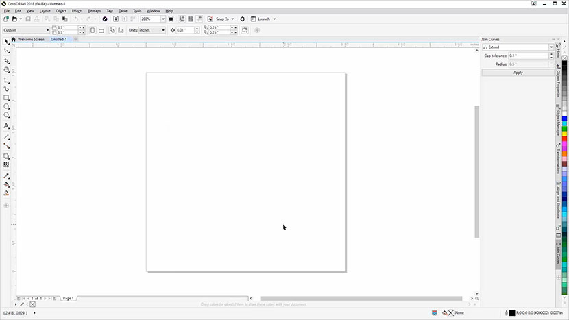
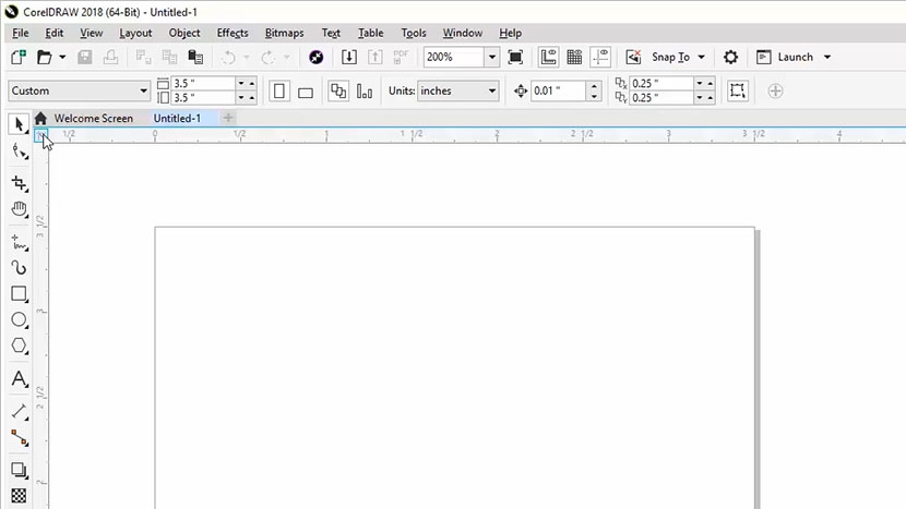
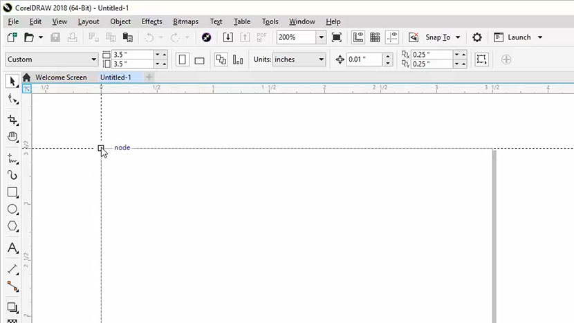
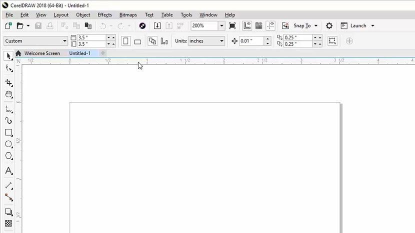
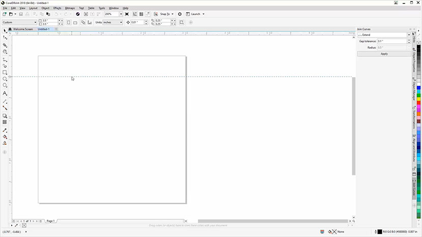
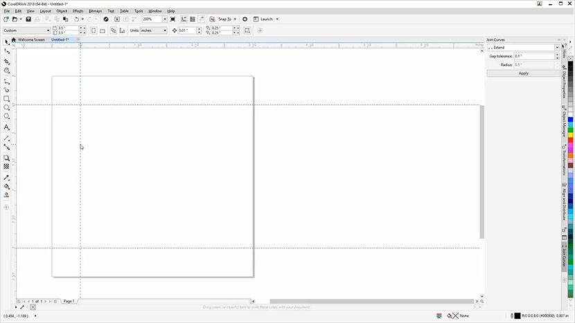
Before we get started, we need to confirm that the top left corner of our page is set to the origin for both of the ruler bars. Look at your Horizontal and Vertical rulers to determine if the top left corner of your page is set to 0 for the Horizontal Ruler and 0 for the Vertical Ruler. If they are, you’re all set. If not, locate the Origin Point tool at the top left corner of your work area.

Then click and drag to the top left corner of your page to set the new Origin point.

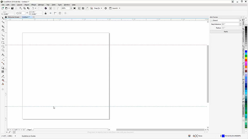
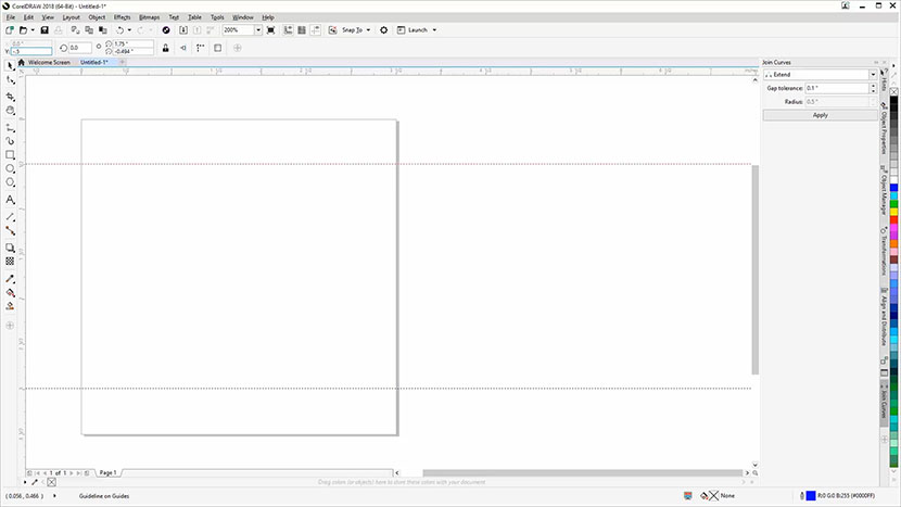
To create our guidelines, we’ll start by creating two horizontal guides for the top and bottom boundaries.

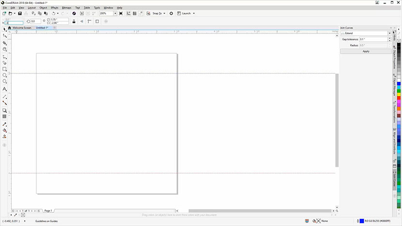
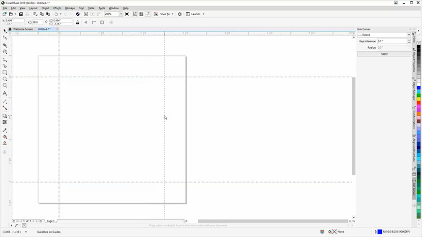
Click on the ruler at the top of the page and drag one guide down to -1/2 inch and another to -3 inches.

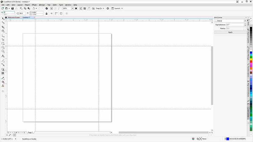
You may find it easier to click and drag the guides to the approximate location, then type in the specific Y Object Position values for each of the guidelines in the Properties bar located at the top of the screen.

Next, we’ll create two vertical guides for our left and right boundaries.

Click on the ruler at the left side of the page and drag one guideline across to 1/2” and another to 3”.

Again, you may find it easier to drag the guidelines to the approximate locations, then key in the 1/2” value for the first guide and the 3” value for the second guide in the X Object Position box in the Properties bar.

Importing a Graphic

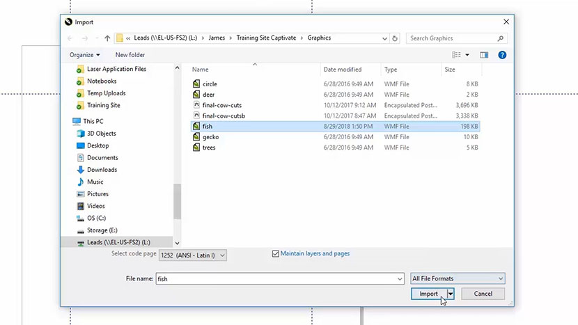
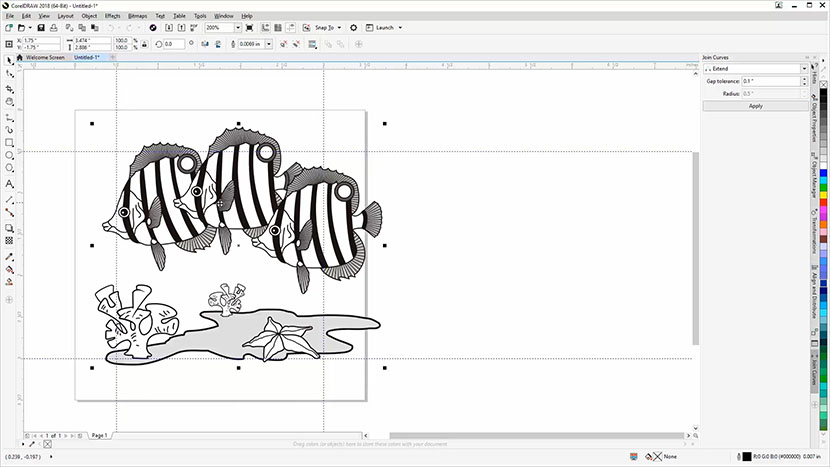
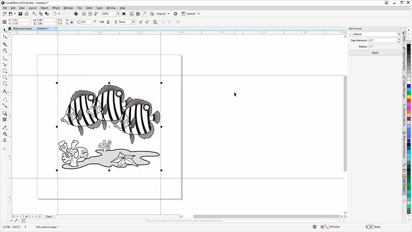
Now we’re going to import a graphic and center it to the page. Here we’ll use a fish graphic (fish.wmf ) for this example, but you can use any graphic you prefer.

Start by clicking File at the top of the screen, then select Import from the drop-down menu.

Navigate to the file you’d like to Import, then select the file and click the Import button.

Now, click anywhere on the page to place the graphic.

Centering

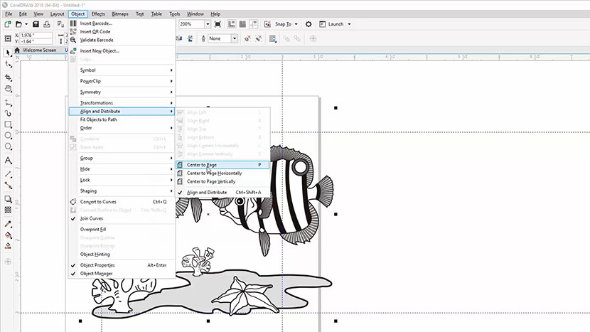
Next, we’ll center the image to the page.

Make sure the object is still selected, then click Object from the drop-down menu at the top of the screen, then Align and Distribute, then Center to Page.

You can also use the shortcut option of pressing the letter P on your keyboard to center the image to the page.

Resizing

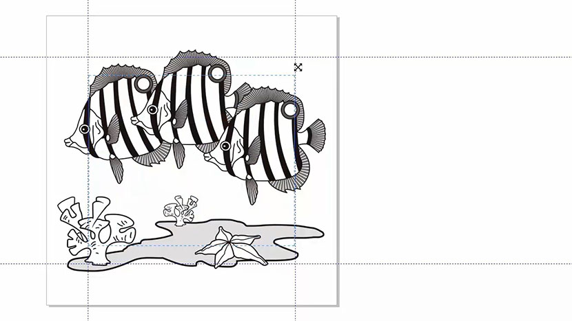
Now we need to resize the fish image to fit inside our boundary guidelines.

To resize the graphic, we’ll click and drag on the top right resizing handle to resize the image and make it smaller.

By clicking on the top-right sizing handle, then holding the Shift key and dragging toward the center of the image, we can keep the proportions of the image the same as we make it smaller.

Drag the sizing handle until the right or left side of the fish graphic aligns with a vertical guideline.

Mirroring for Backside Engraving

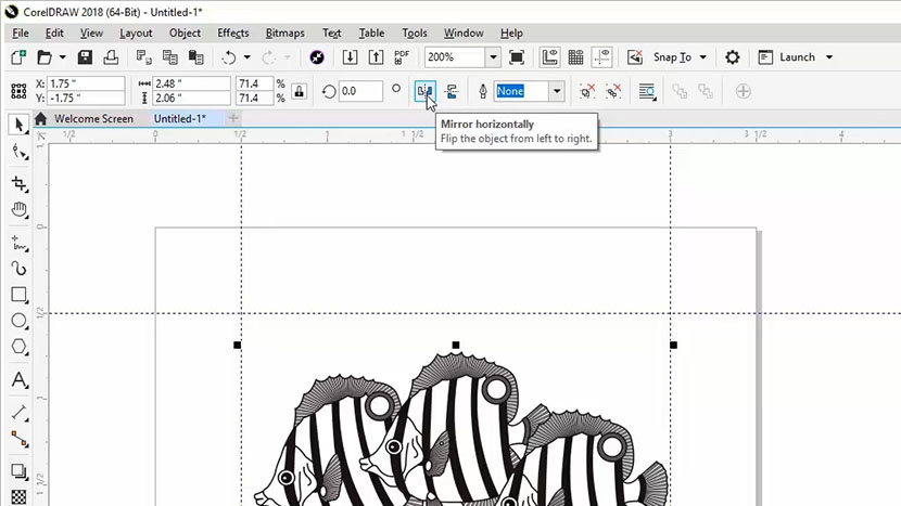
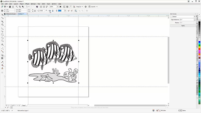
As a final step before printing our graphic to the laser, we want to mirror the graphic for engraving on the bottom side of the glass coaster. Engraving the back of glass will give you the best result when viewed through the other side, and doing so will help protect your engraving from wear and tear.

For backside engraving on glass, it’s important to mirror your graphic. If there is text in your graphics, you want the text to read forward instead of backward once viewed from the top or other side of the piece.

To mirror the graphic, select the graphic with the Pick Tool, then click on the Mirror Horizontally button in the Properties bar at the top of the screen.

Printing to the Laser

Next, we’ll print the file to the laser.

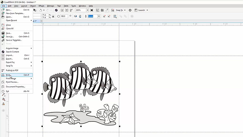
Select File, then Print from the dropdown menu, or press Ctrl + P on your keyboard.

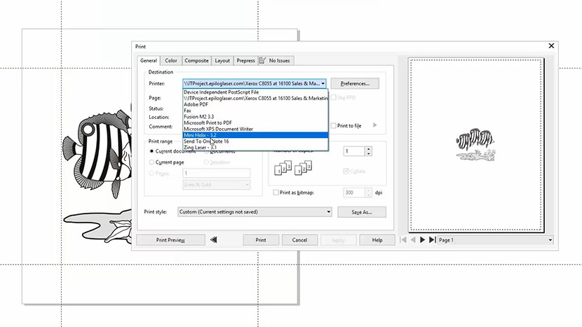
Select your laser from the printer options, then click the Preferences button.

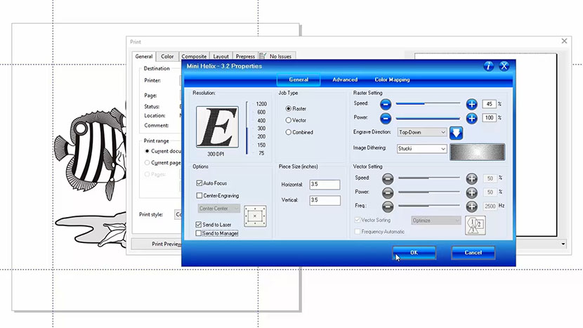
In the Laser Dashboard:

  • Set your Resolution to 300 dpi (When engraving glass we don’t need to use a high resolution to get a good engraving.)
  • Select Raster from the Job Type options (We only need Raster since we’ll only be engraving this file.)
  • Set the Speed to 45% and Power to 100% (Refer to your laser manual for the suggested speed, power, and frequency settings for etching glass with your wattage of laser.)
  • Select Stucki as the Image Dithering pattern. (Since we are engraving this at a lower resolution, this will randomize the dot pattern in the graphics and give us a higher-quality frosted look to our engraving.)
  • Set the piece size to match your page size. Set the horizontal and vertical size to 3.5 inches.
  • Select Auto-Focus in the Options section.
  • Make sure Send to Laser is checked.
  • Uncheck Send to Manager

Then click the OK button.

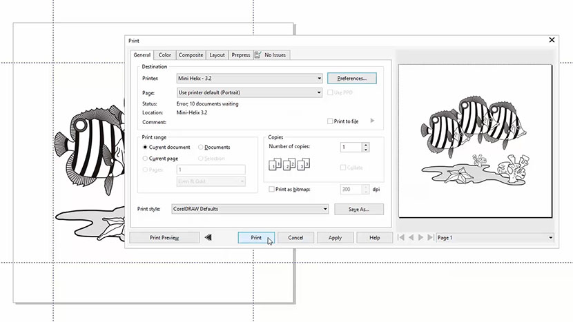
The print preview should now look like our Corel file.

Finally, click Print to send the job to the laser!

At the Laser!

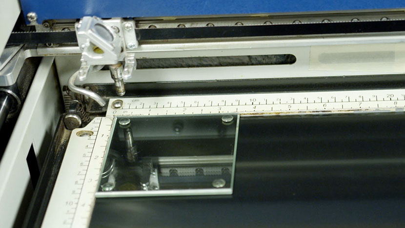
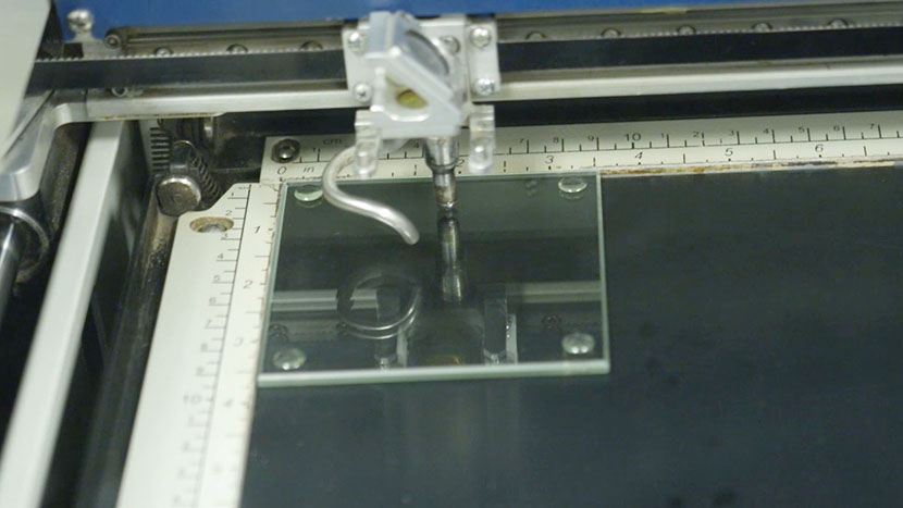
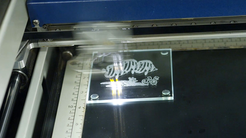
At the laser, we’ll place the glass coaster into the top left corner of the work area.

With Auto-Focus selected in the print driver, the laser will handle focusing the table with focus plunger, then begin engraving once the coaster is in focus.

Press the Go button on the keypad to start your glass engraving job.

And then you’re done!
Wood Square

Setting Up Your Page

We’ll start by creating a new file in CorelDRAW. Click File in the menu bar at the top of the screen. Then select New from the drop-down list.

Now enter your page size. Enter 4.5” for the page width and 4.5” for the page height. Then click OK.

Importing and Resizing a Graphic

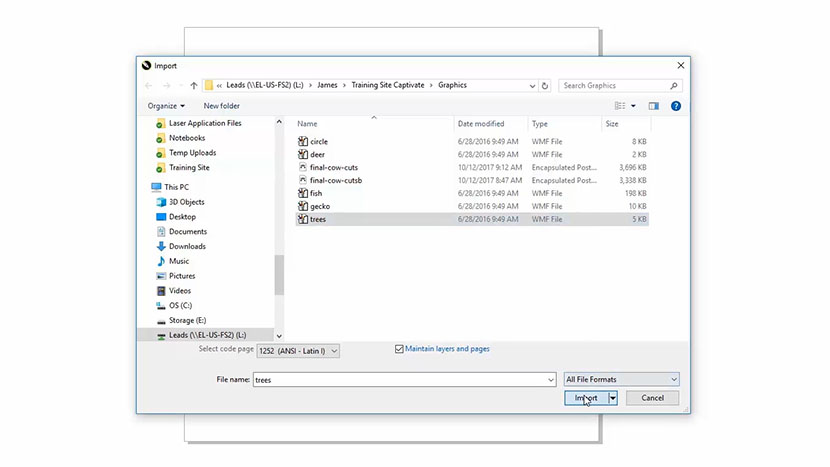
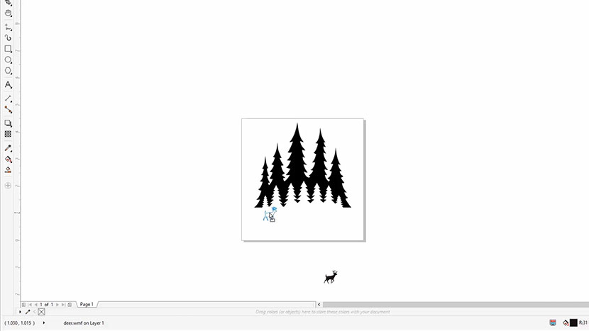
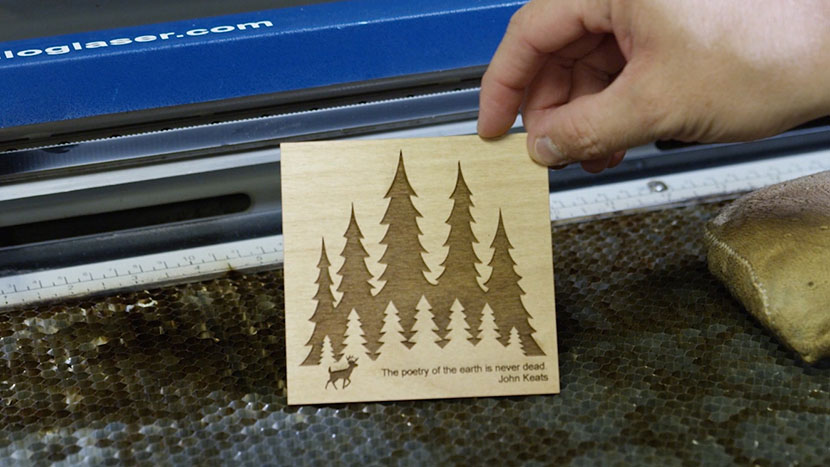
Now we’re going to import a graphic onto the page. For this example we will use trees.wmf , but you can use any graphic you prefer.

Start by clicking File at the top of the screen, then select Import from the dropdown menu.

Navigate to the file you’d like to Import and select the file, then click the Import button.

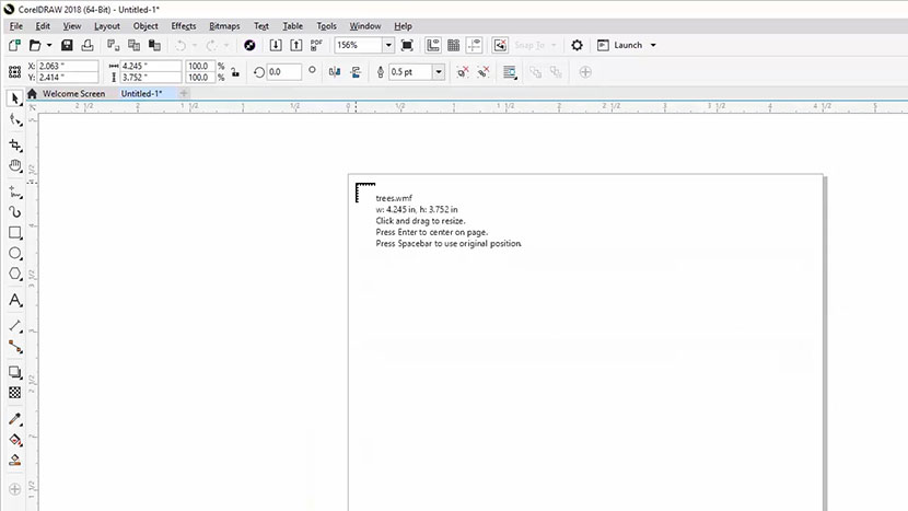
Now, click anywhere on the page to place your graphic.

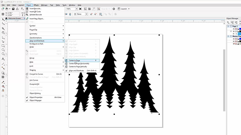
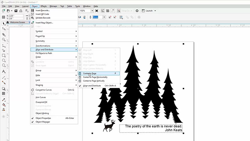
To center the image on the page, select Object from the menu bar.

Then select Align and Distribute, then Center to Page.

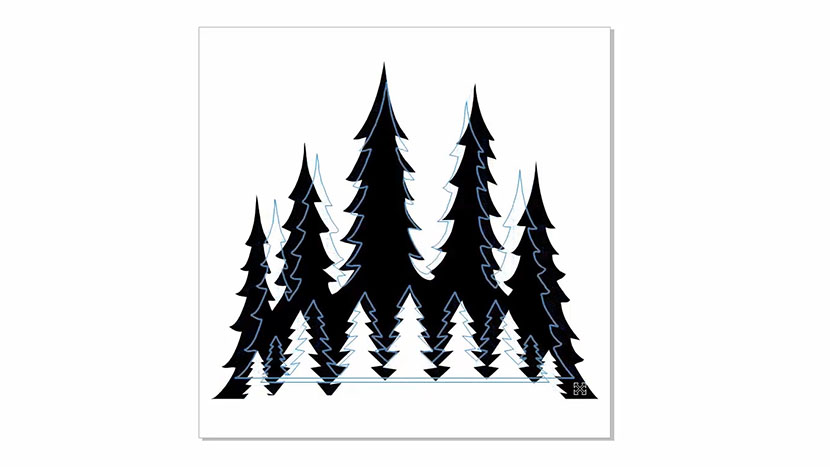
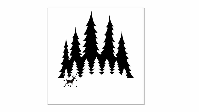
Now we’ll click and drag on the bottom right sizing handle to resize the image, and make it smaller. By holding down the shift key then clicking on the handle and dragging, we can keep the proportions of the image the same.

Next we’ll reposition the image by moving it up by about 1” on the page by clicking on the graphic and dragging it up.

Importing a Second Graphic

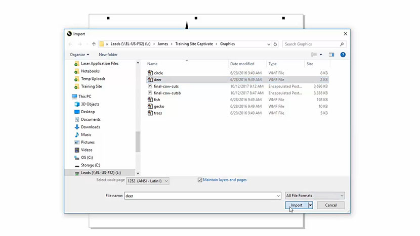
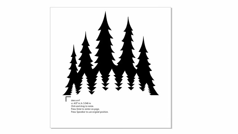
Now let’s import another image. Go to File > Import, and we’ll choose the deer file (deer.wmf ). Then Press the Import button.

Click anywhere on the page to place the graphic.

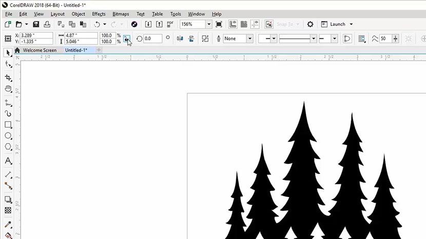
This time we’ll use another way to resize the deer. Click the lock ratio button to keep the dimensions the same as we resize the graphic.

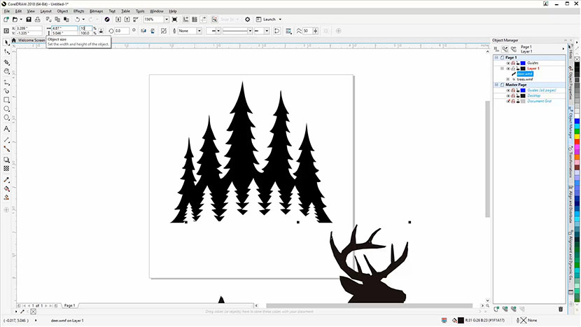
Enter 10% as the scale factor and press Enter to resize the image to 10% of its original size.

We’ll position the deer image to the bottom left side of the trees.

Adding Text to the Artwork

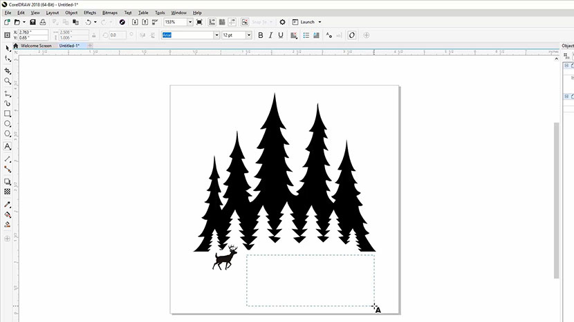
Now we’re ready to add text. Click on the text tool in the tool bar on the left.

Create a text box by clicking and dragging a rectangle next to the deer.

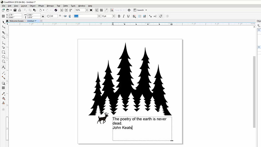
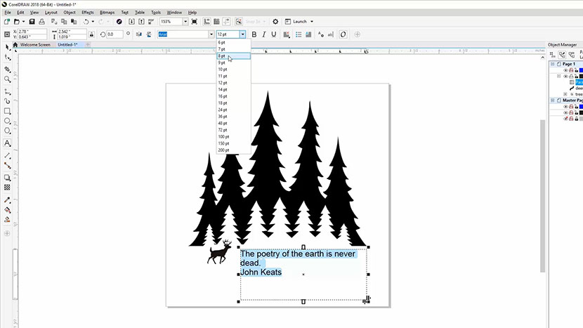
We’ll enter our text “The poetry of the earth is never dead.” Then press Enter and type “John Keats”.

Select the pick tool, select the text, and then change the font size to 8 pt.

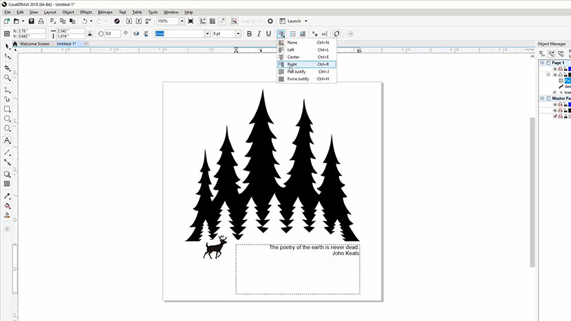
Next select the right justify option to align the text to the right side of the text box.
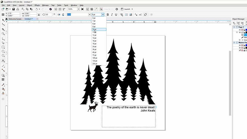
8 pts. is a little small so we’ll go ahead and change that to 10 pts.

Before we move on let’s make the text box a little smaller. Select the Pick Tool, then click on the text box. Now click on the bottom middle sizing handle and drag it up to make the text box a little smaller.

Selecting, Grouping, and Resizing

Press Ctrl and A to select everything on the page.

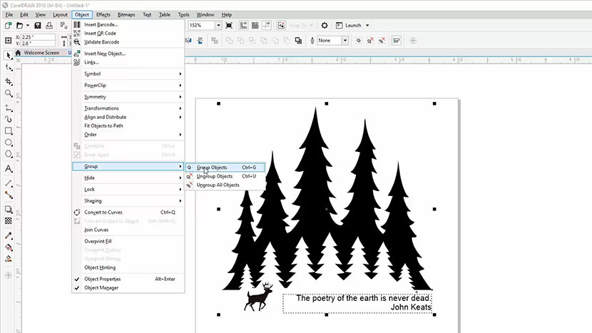
Next we’ll group the items so they all stay together when we make changes. Click Object in the menu bar, then Group, then Group Objects.

Now we’ll center the images. Click Object, Align and Distribute, Center to Page.

Creating a Cut Line

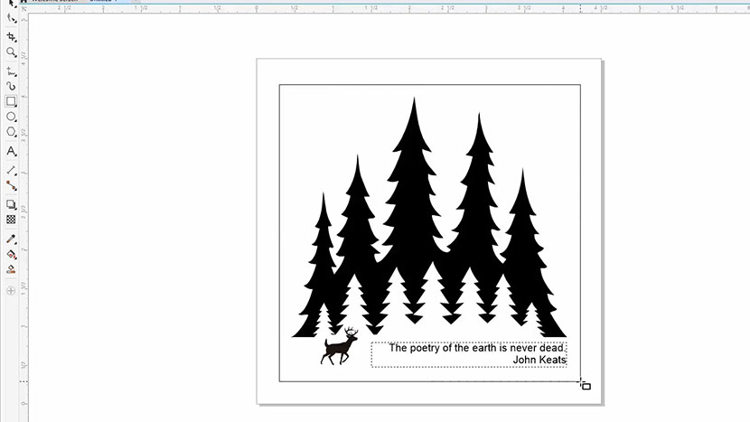
Now let’s create a cut line. Click the rectangle tool, and then click and drag a rectangle around the image. We’ll center the box we’ve drawn by using the shortcut of pressing the letter P on the keyboard. This will center the box to the page.

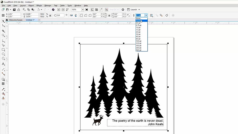
Now select the pen tool drop down box at the top of your screen to set the line thickness. We’ll select ‘hairline’ from the dropdown menu. This is important; to laser cut a line you need to set the line width to under .004”. In Corel, hairline thickness will always cut.

Printing to the Laser

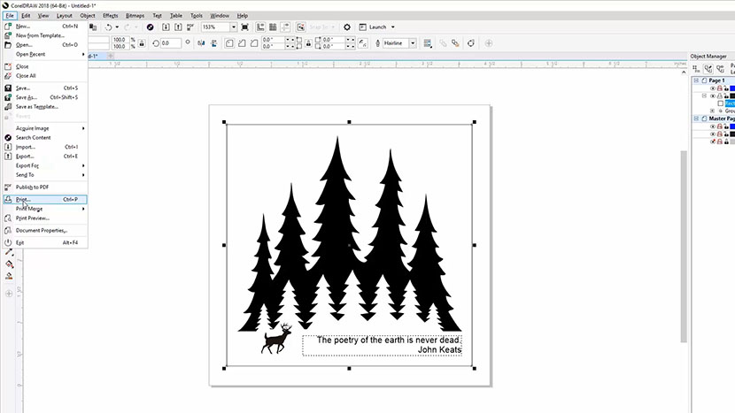
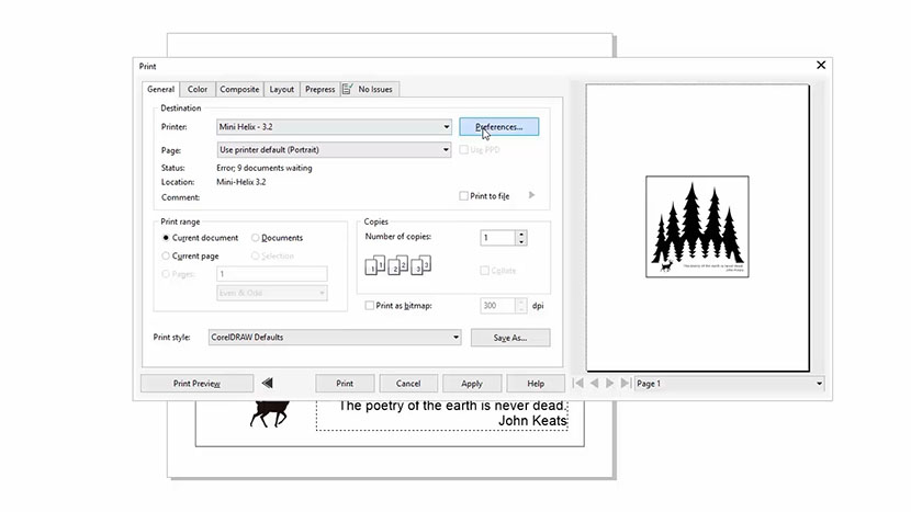
Next we’ll print the file to the laser. Select File, then Print from the drop-down menu.

Set your Mini/Helix laser as your printer and then click the Preferences button.

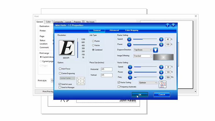
In the print driver, first set your resolution to 500 dpi.

Since we have both engraving (raster) and cutting (vector) parts of this file, choose combined as the job type.

Now we’ll set up the speed and power settings. You can find the suggested settings for your wattage in your manual’s appendix. We’ll set the speed to 40%, then set the power of the laser to 100%.

Next set your cutting speed and power. Use the 1/8” wood vector settings in your manual. We’ll set the speed to 30% and the power to 100%

Next, set the frequency to around 500. This is the pulse rate of the laser and a lower pulse rate is preferable for wood cutting to achieve less burning on the edge of the wood.

Set the piece size to match your page size. We’ll set the horizontal size to 4.5” and the vertical to 4.5” as well.

Make sure Send to Laser is checked, and for this example, we’ll go ahead and uncheck the Job Manager option. Then click the OK button.

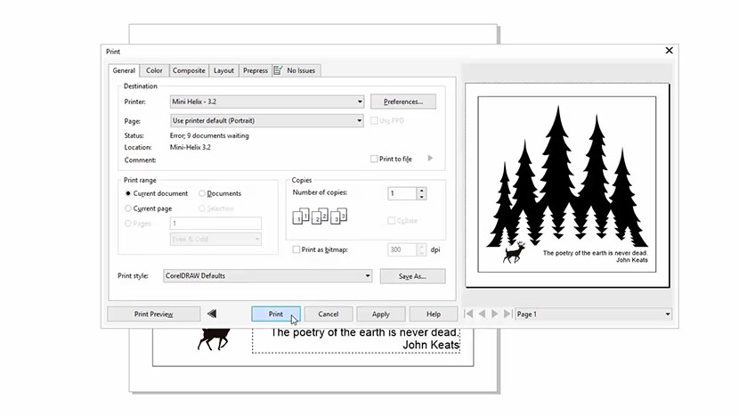
The print preview should now look like our Corel file.

Finally, click Print to send the job to the laser!

At the Laser

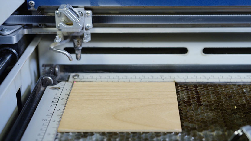
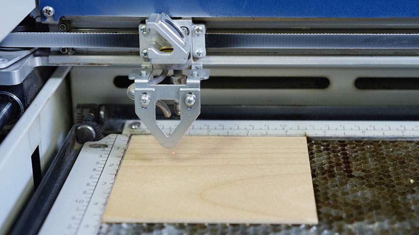
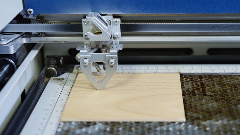
At the laser, we’ll place the 4” square wood piece into the top left corner of the work area.

Hang your manual focus gauge on the optics assembly. Then press the Focus button on the keypad to bring the manual focus gauge out over the work area.

Now press the Up Arrow on the keypad to move the table up and bring the material into focus.

Once you’ve focused for your material, press the Reset button.

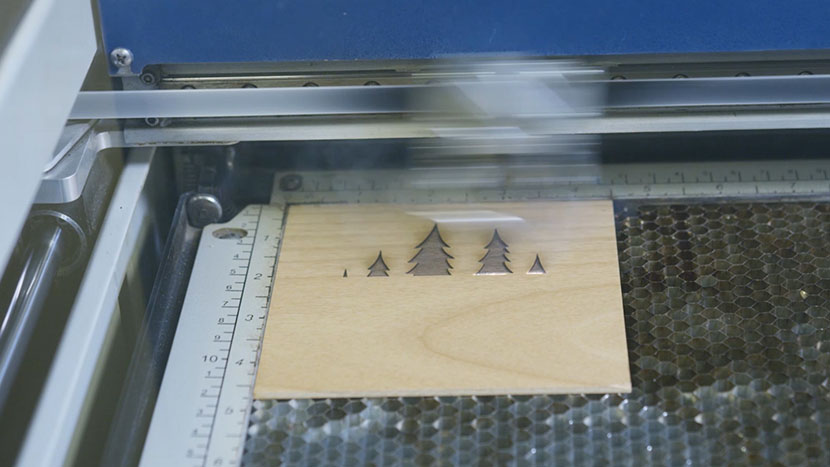
Now we’re ready to start the job. Press the Go button on the keypad to begin your laser engraving and cutting job.

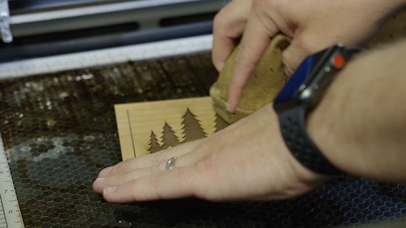
Once the laser is finished, use a damp sponge or towel to remove any leftover residue or debris.

And then you’re done!
X-Axis Assembly Replacement

Remove Side Panels

Shut off the laser and remove the power cord from the machine.

Flipping the machine's power switch.

Remove the left side panel by loosening the four screws on its main face, as well as the two screws on the back.

Removing the screws on the left panel's main face.Removing the screws on the left panel's back face.

Pulling the left panel off of the chassis.

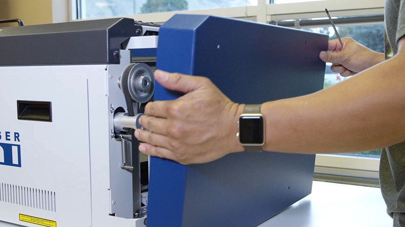
Remove the right side panel by loosening the four screws on its main face, as well as the two screws on the back.

Removing the screws on the right panel's main face.Removing the screws on the right panel's back face.

Pulling the right panel off of the chassis.

Remove X-Axis Assembly

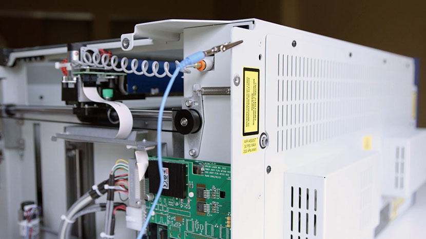
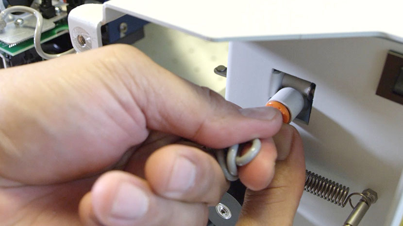
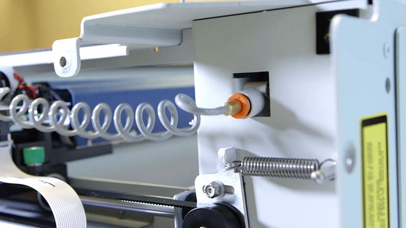
Disconnect the Air Assist Coil by pushing in the orange ring and then pulling the air hose out.

Grasping the Air Assist Coil.

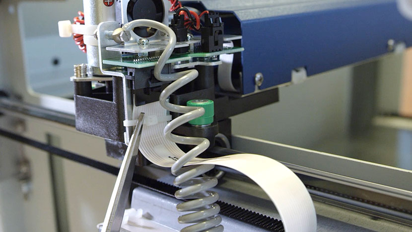
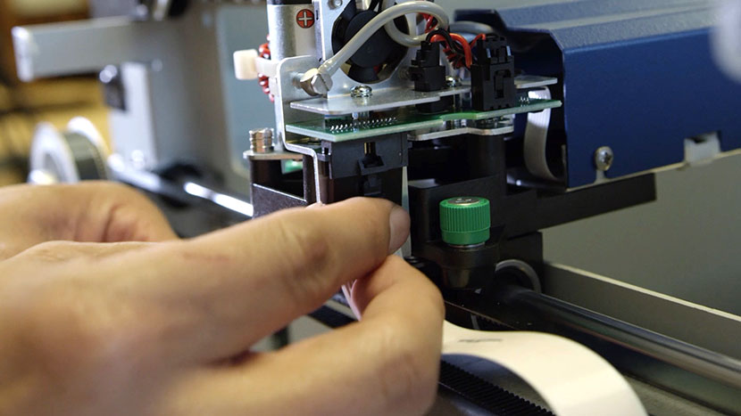
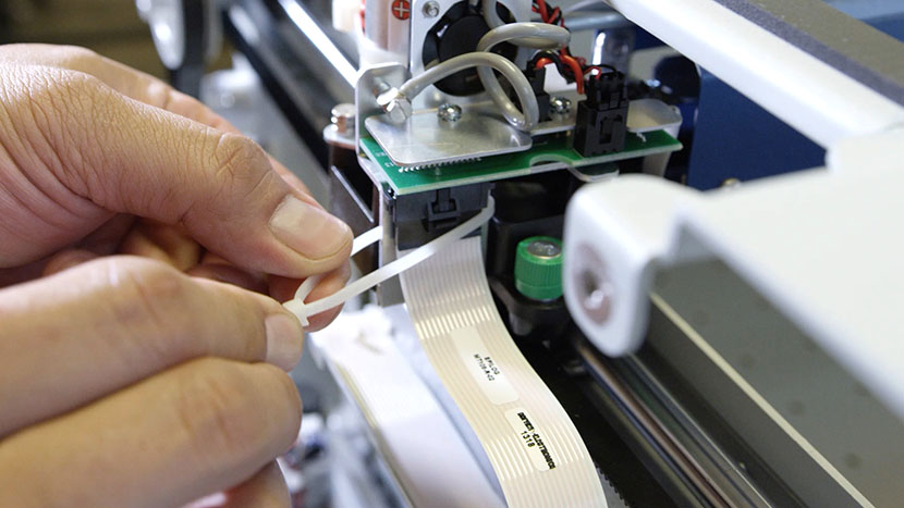
Cut the white zip tie around the white ribbon cable.

Scissors cutting the zip tie around the white ribbon cable.

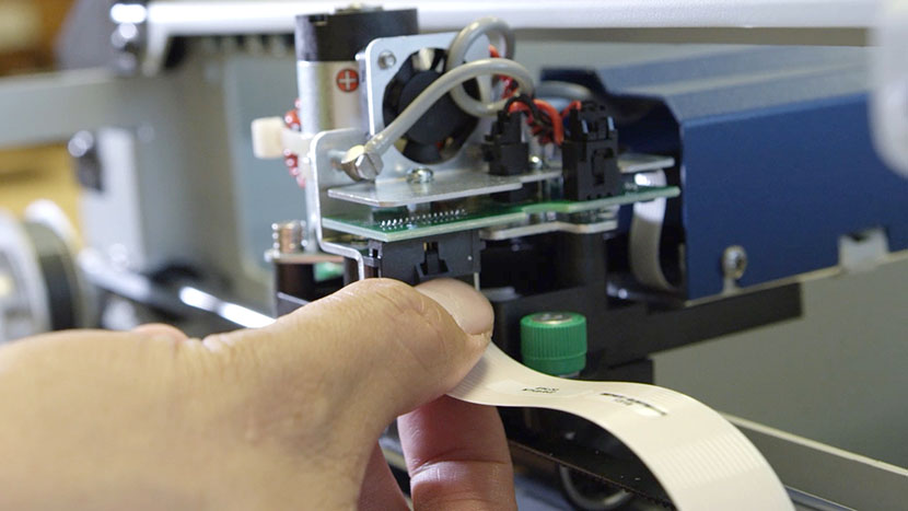
Disconnect the Y-Axis flex cable.

Pulling out the Y-Axis flex cable.

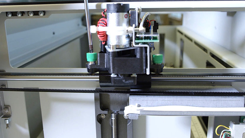
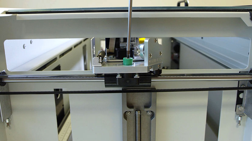
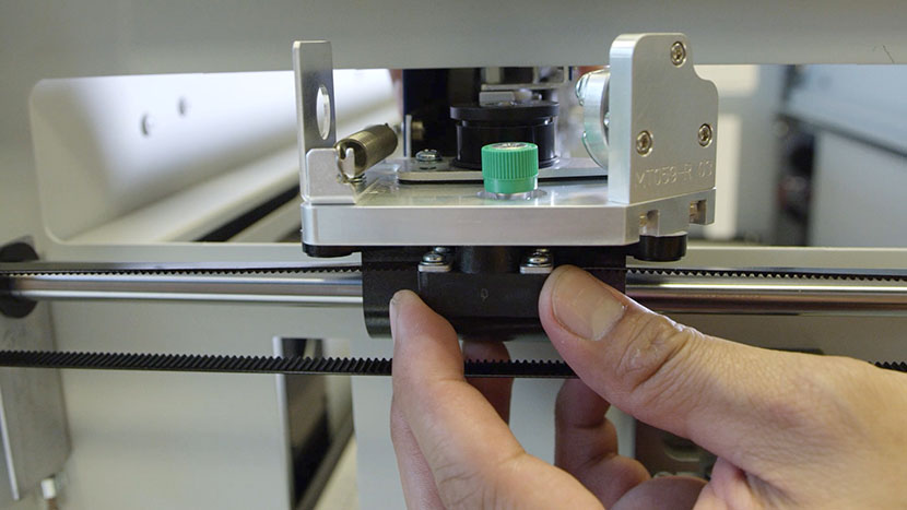
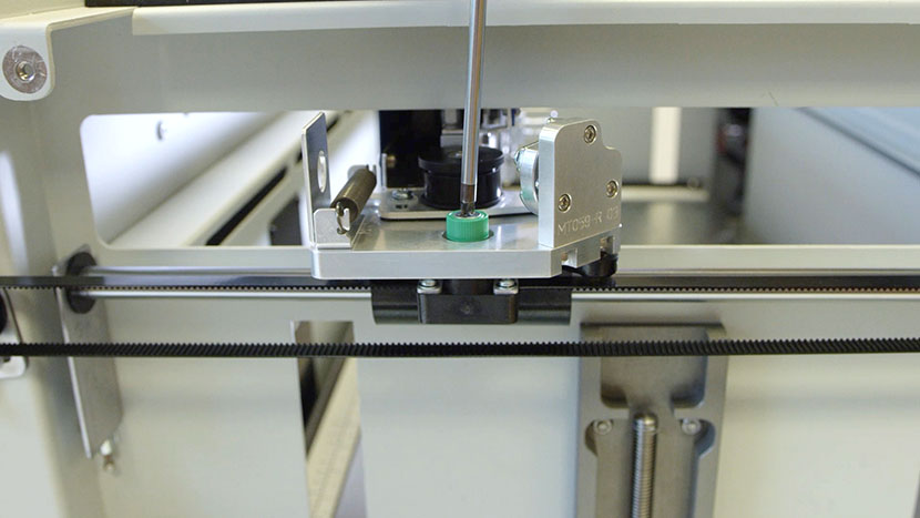
Unscrew the two green captive screws on the right side of the X-Axis Assembly.

Unscrewing the front captive screw on the right side of the X-Axis Assembly.Unscrewing the back captive screw on the right side of the X-Axis Assembly.

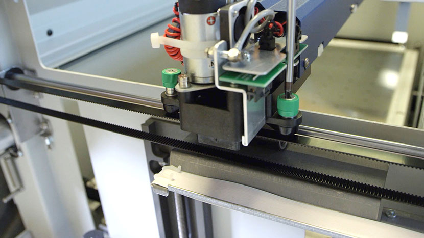
Unscrew the green captive screw on the left side of the X-Axis Assembly.

Unscrewing the green captive screw on the left side of the X-Axis Assembly.

Open the lid of the machine.

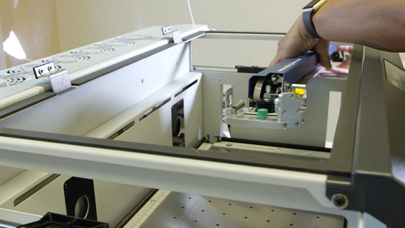
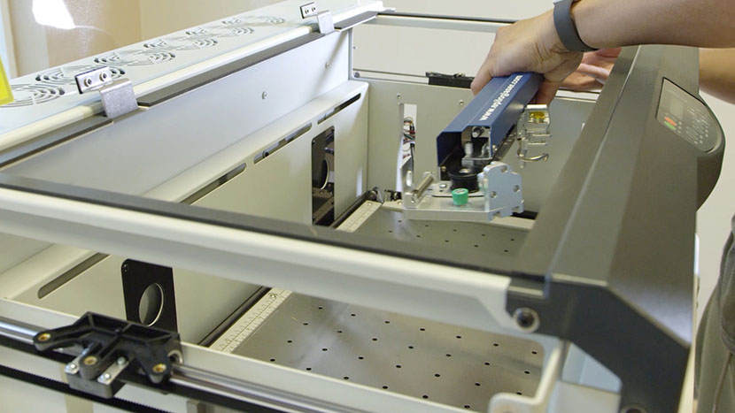
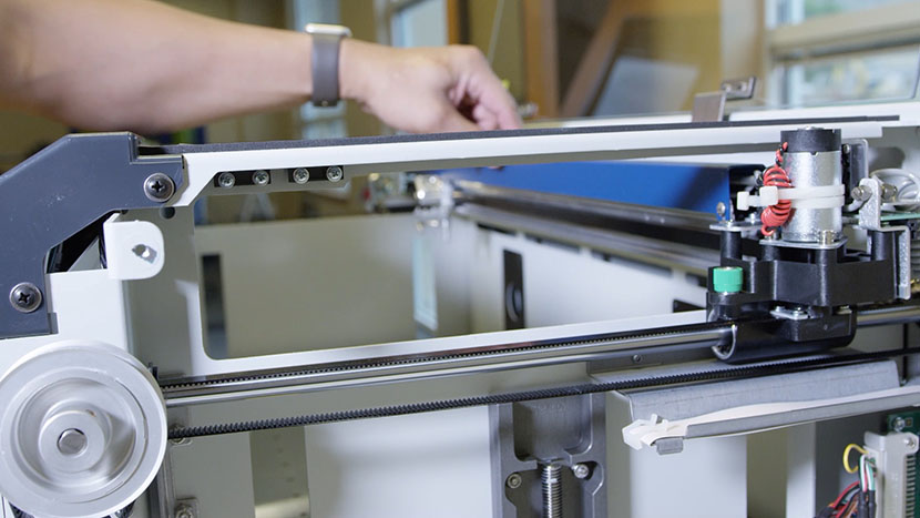
To remove the X-Axis Assembly, lift it carefully, especially when lifting the right side of the Assembly. Bring the right side forward a little to ensure the motor clears the frame rail.

Pulling the X-Axis Assembly out the right side of the machine.

Reinstall X-Axis Assembly

Install the X-Axis assembly by placing the Assembly on the brackets, making sure to line up the Assembly onto the pins.

Putting the X-Axis Assembly back in through the right side of the machine.Placing the X-Axis Assembly on its mounting pins.

Tighten the green captive screws on both sides of the X-Axis Assembly.

Tightening the green captive screw on the left side of the machine.Tightening the green captive screws on the right side of the machine.

Move the X-Axis Assembly to the front and back to make sure the Y-axis moves smoothly.

Pushing the X-Axis Assembly to the back of the machine.

Reconnect the Y-Axis flex cable and secure it with a Zip Tie.

Plugging in the Y-Axis flex cable.

Reconnect the Air Assist Coil.

The Air Assist Coil plugged into the machine.

Reinstall Side Panels

Replace the right side panel, inserting the four screws on the panel’s main face, as well as the two screws on the back.

Putting on the right side panel.

Inserting the screws on the main face of the right side panel.Inserting the screws on the back of the right side panel.

Replace the left side panel, inserting the four screws on the panel’s main face, as well as the two screws on the back.

Putting on the right side panel.

Inserting the screws on the main face of the left side panel.Inserting the screws on the back of the left side panel.

Plug the machine in and turn it on.

Plugging the power cord into the machine.

X-Motor Replacement

Remove Side Panels

Shut off the laser and remove the power cord from the machine.

Flipping the machine's power switch.

Remove the left side panel by loosening the four screws on its main face, as well as the two screws on the back.

Removing the screws on the left panel's main face.Removing the screws on the left panel's back face.

Pulling the left panel off of the chassis.

Remove the right side panel by loosening the four screws on its main face, as well as the two screws on the back.

Removing the screws on the right panel's main face.Removing the screws on the right panel's back face.

Pulling the right panel off of the chassis.

Loosen X-Axis Belt

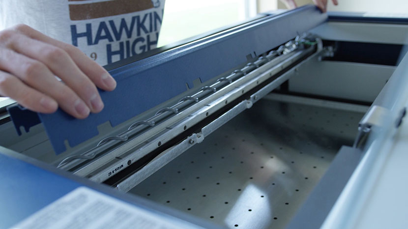
Remove the cover on the X-Axis Assembly by loosening the screws on the front and rear of the beam and pulling the cover up. Do not remove these screws completely.

Loosening the screws on the front of the X-Axis Assembly.Loosening the screws on the back of the X-Axis Assembly.

Lifting the cover off of the X-Axis Assembly.

Loosen the X-axis belt as follows:

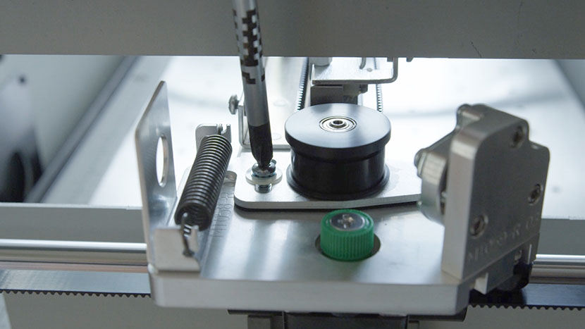
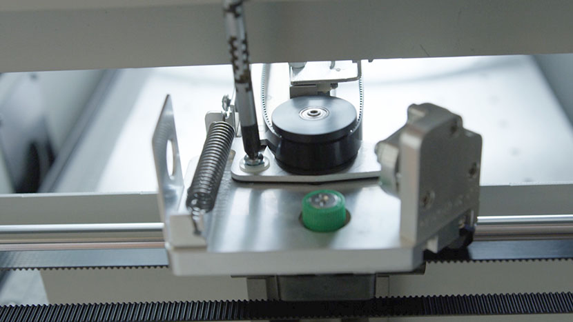
On the left side of the X-Axis Assembly, locate the idler pulley that the belt wraps around. It is mounted to a sliding plate which has one screw and a spring attached.

Loosen the Philips screw that holds the sliding plate in place.

Loosening the screw that holds the sliding plate in place on the left end of the X-Axis Assembly.

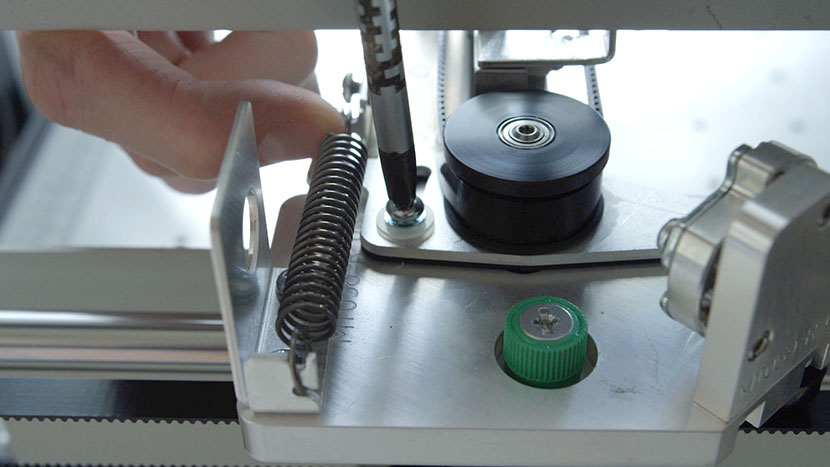
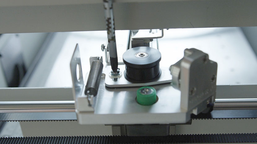
While holding the sliding plate to the right hand side of the engraver, tighten the screw. This will hold the pulley in place and keep tension off of the X-axis belt.

Holding the sliding plate to the right hand side of the engraver and tightening the screw.

Remove Old X-Motor

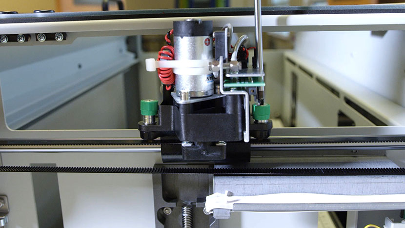
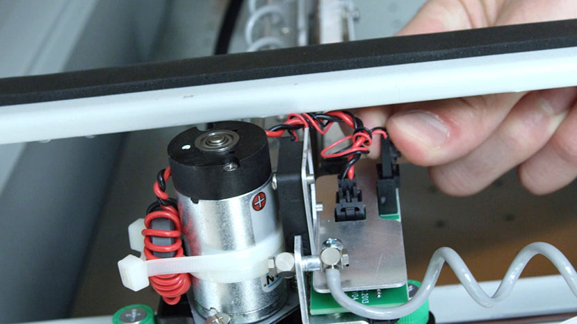
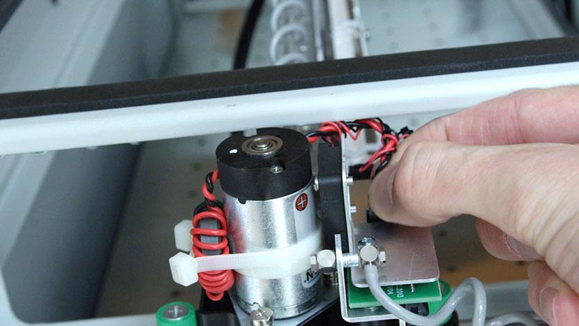
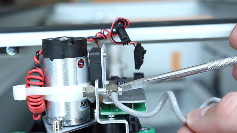
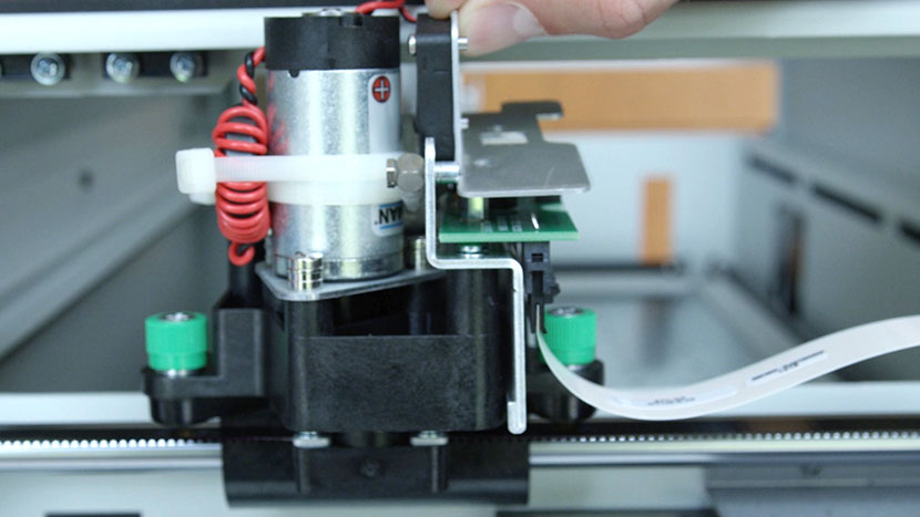
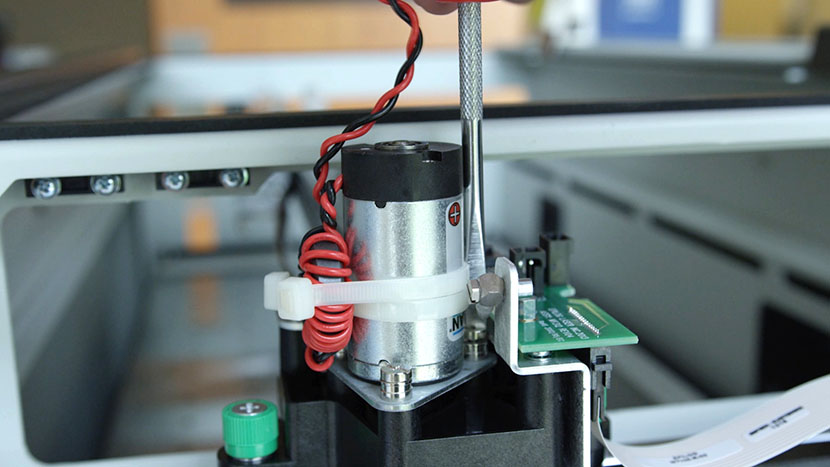
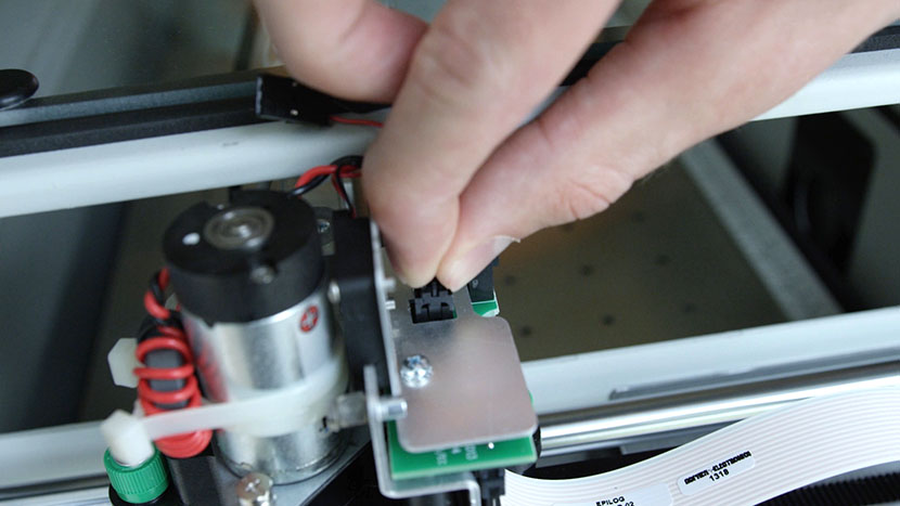
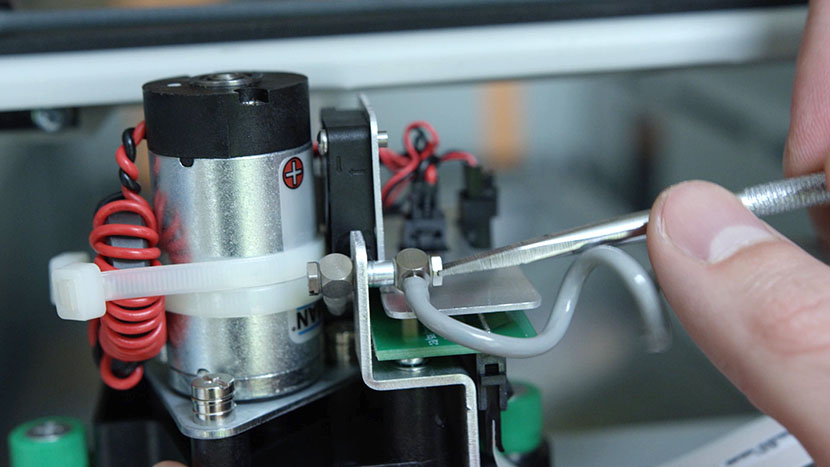
Identify the Motor Assembly on the right side of the X-Axis Assembly. Locate the motor wires and remove them by squeezing the quick-disconnect plugs between your thumb and forefinger to release the connectors from their sockets.

Unscrewing the Air Assist Coil from the end of the X-Axis Assembly.Unplugging the two black connectors from the circuit board.

Remove the Air Assist Coil.

Grasping the X-Axis flex cable.

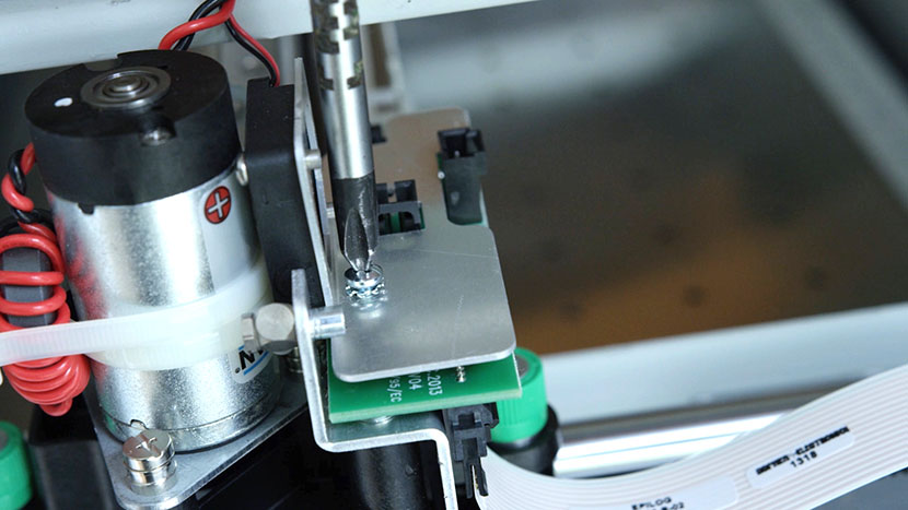
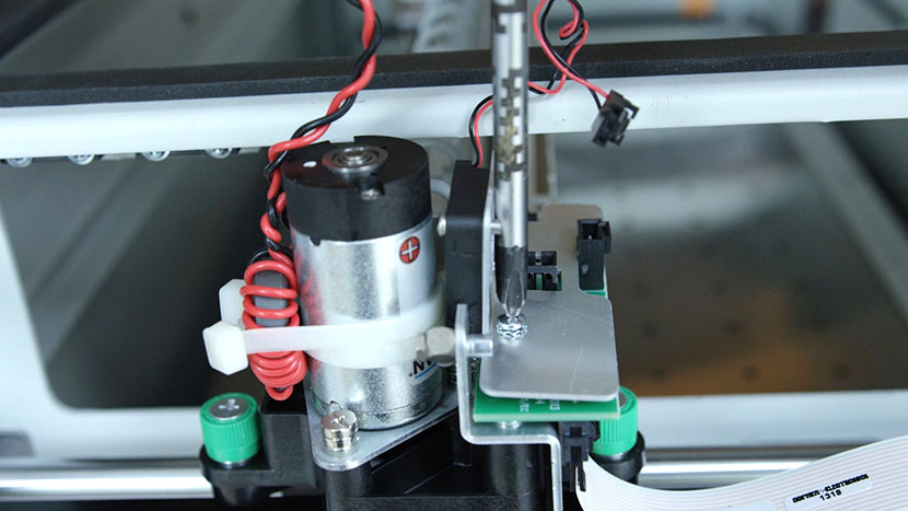
Unscrew and remove the fan assembly.

Unscrewing the two screws that secure the fan assembly.Lifting the fan assembly off the circuit board.

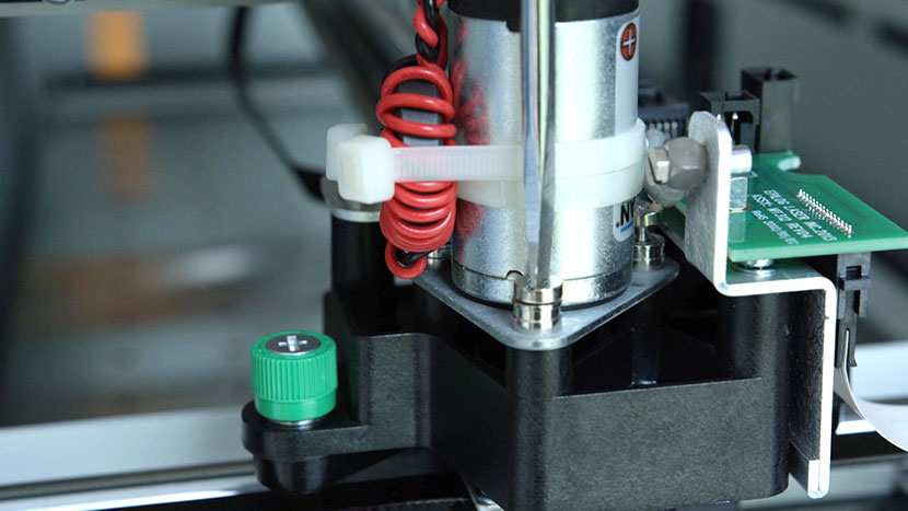
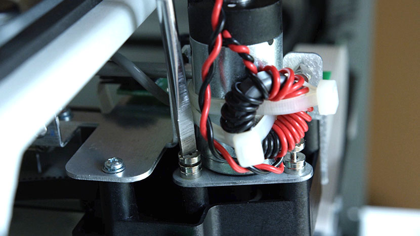
Identify and unscrew the captive screws which mount the motor to the X-Axis Assembly.

Unscrewing one of the captive screws securing the X-Motor.Unscrewing one of the captive screws securing the X-Motor.

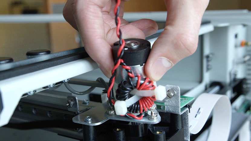
Remove the motor by pulling it straight up. You may need to angle the motor slightly so that the belt falls from the drive pulley.

Removing the X-Motor.

Install New X-Motor

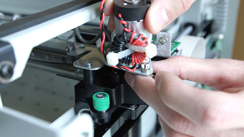
Install the new X-Motor. With your index finger, pull the belt and loop the belt around the silver pulley. Place the motor so that the captive screws are aligned with the mounting posts.

Installing the new X-Motor.

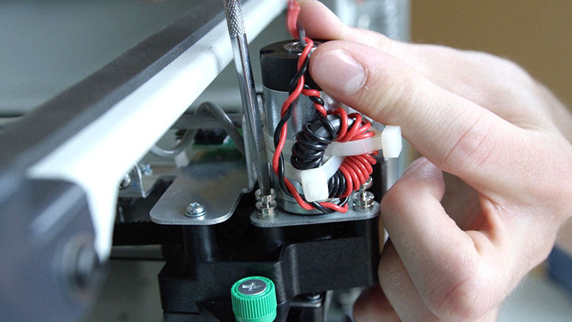
Tighten the captive screws to hold the motor in place.

Tightening the captive motor mounting screws.Tightening the captive motor mounting screws.

Replace and fasten the fan assembly over the circuit board.

Reattaching the fan assembly over the circuit board.

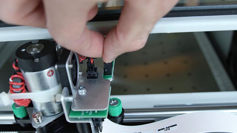
Connect the motor and fan wires by plugging the black connectors into the circuit board.

Connecting the motor plug into the circuit board.Connecting the fan plug into the circuit board.

Reconnect the Air Assist Coil.

Reconnecting the Air Assist Coil.

On the left side of the X-Axis Assembly, locate the pulley which the belt wraps around. Loosen the Philips screw holding the sliding plate in place. The spring will pull the belt tight.

Loosening the screw that holds the pulley sliding plate in place.

Retighten the Philips screw to keep the belt tight as the engraver operates.

Tightening the screw that holds the pulley sliding plate in place.

Check that the belt is on the center of both pulleys on the left and right sides of the assembly.

Replace the cover on the X-Axis Assembly and tighten the screws on the front and rear of the beam.

Putting the cover back on the X-Axis Assembly.

Tightening the screws on the front of the X-Axis Assembly.Tightening the screws on the back of the X-Axis Assembly.

Reinstall Side Panels

Replace the right side panel, inserting the four screws on the panel’s main face, as well as the two screws on the back.

Putting on the right side panel.

Inserting the screws on the main face of the right side panel.Inserting the screws on the back of the right side panel.

Replace the left side panel, inserting the four screws on the panel’s main face, as well as the two screws on the back.

Putting on the left side panel.Inserting the screws on the main face of the left side panel.

Plug the machine in and turn it on.

Plugging the power cord into the machine.

Power Supply Replacement

Remove Old Power Supply

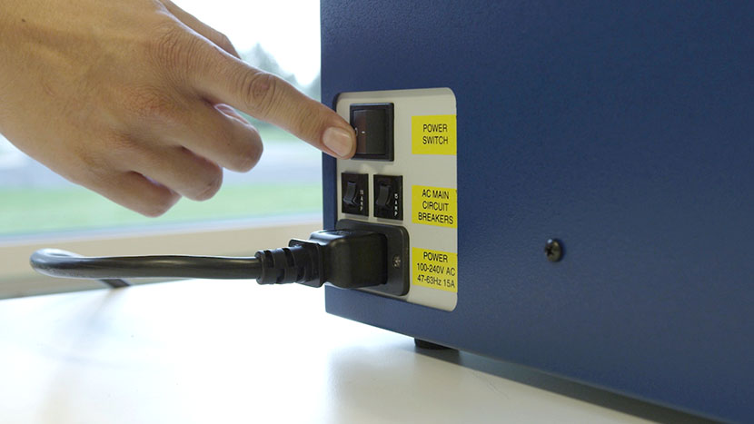
Shut off the laser and remove the power cord from the machine.

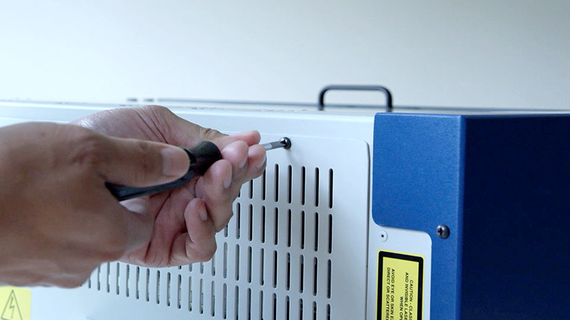
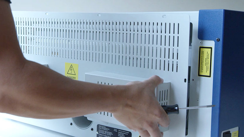
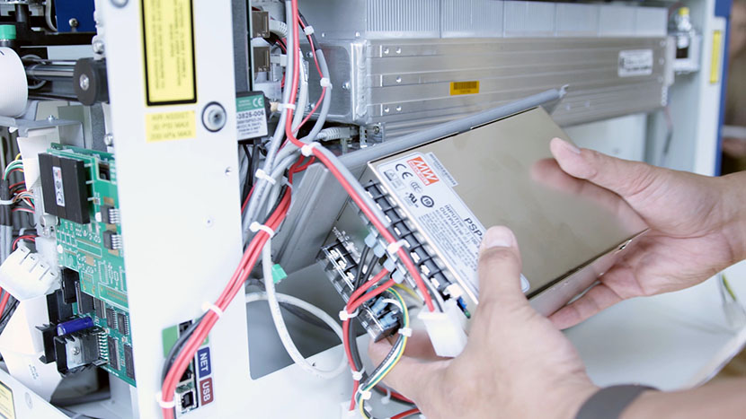
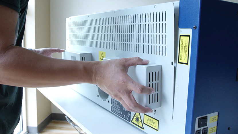
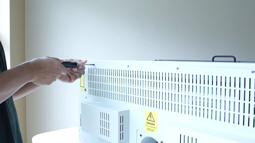
Loosen the 8 screws on the back of the machine and remove the back service panel.

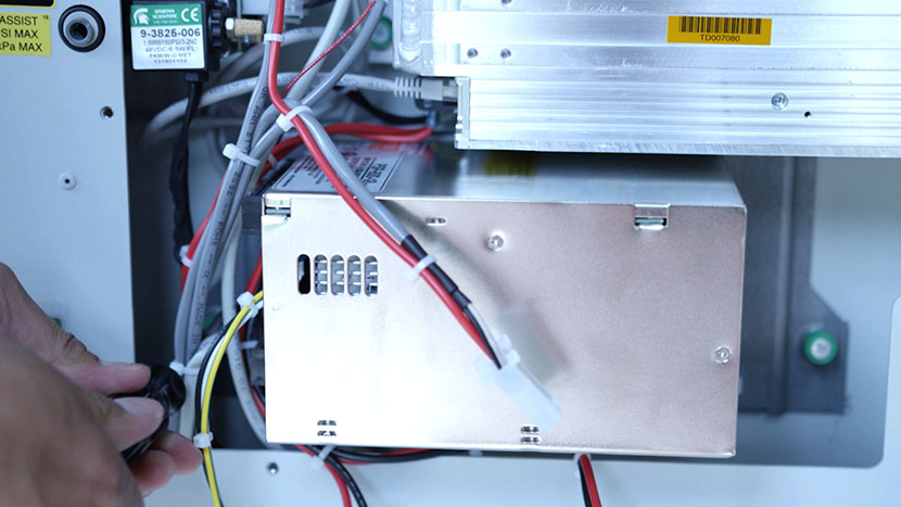
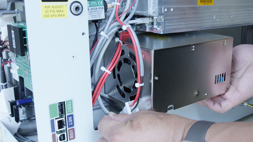
Locate the power supply on the left hand side of the machine.

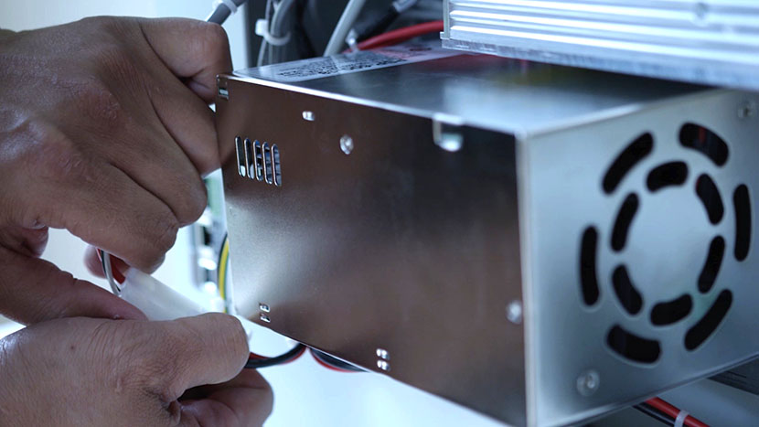
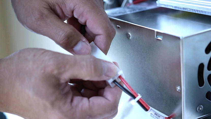
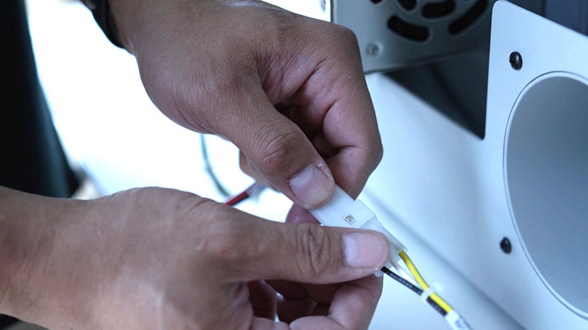
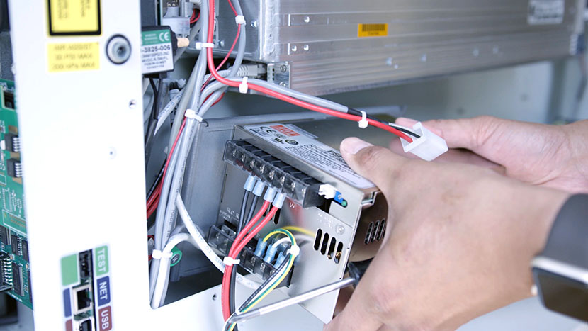
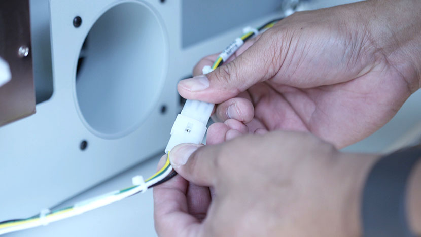
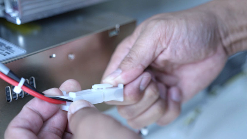
Disconnect the three electrical leads.

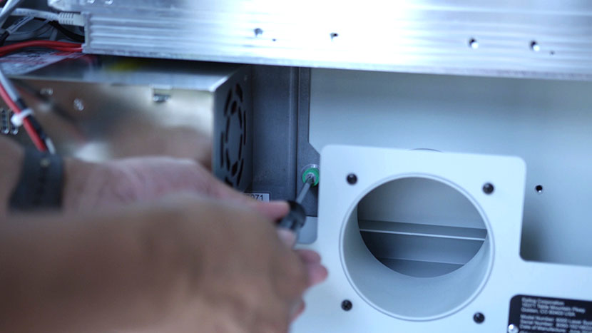
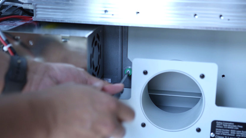
With a Philips head screwdriver, unscrew the green screws located on each side of the power supply.

Remove the power supply from the machine.

Install New Power Supply

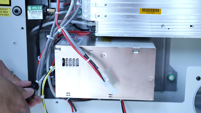
Replace the old power supply with the new one. Position the power supply in the machine with the green captive screws on the bottom.

Tighten the green captive screws.

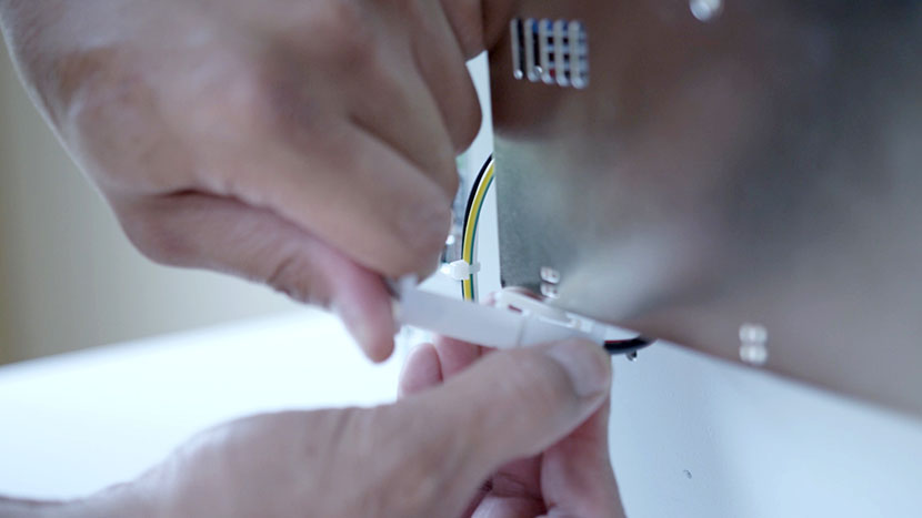
Reconnect the three electrical leads. Reconnect the green with yellow stripe lead to the longer of the two leads coming from the power switch.

Tuck in the wires under the power supply.

Replace the back service panel and tighten all 8 screws.

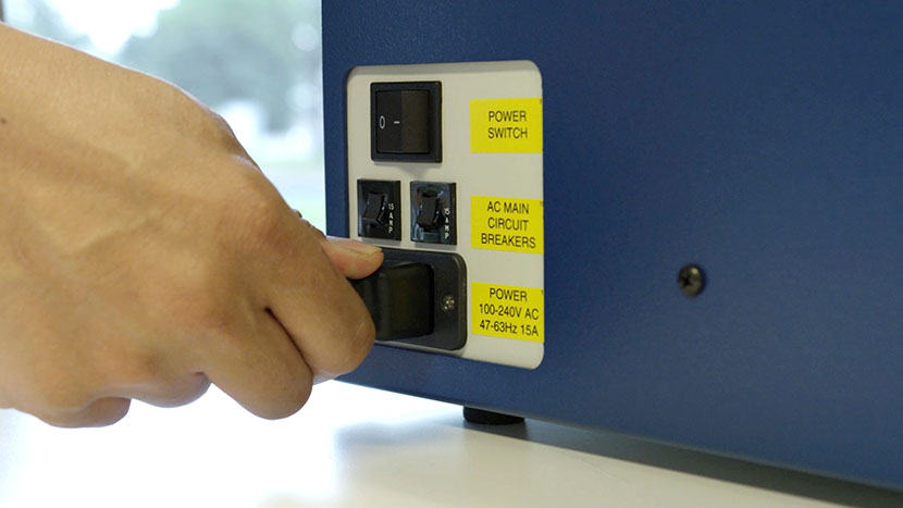
Plug the machine in and turn it on.