
Lesson Category: Fusion

Replacing the Control Panel

Remove Panel

Remove the top access panel on the right side of the machine by using a 5/32” hex key to turn the black panel locks ¾ of the way counter-clockwise.

Remove Old Keypad

From beneath, locate and disconnect the wire harnesses from the back side of the key pad.

Once the wire harnesses have been removed, use a 7/64” hex key to remove the four screws near the corners of the back of the keypad. Remove the keypad assembly.

Install New Keypad

Position the new keypad assembly into the cutout on the engraver.

Use a 7/64” hex key to insert the four screws and secure the new keypad assembly.

Reconnect the wire harnesses to the back of the keypad assembly. The lower connector accepts the wire harness leg that has mostly yellow wires attached. The upper connector accepts the harness with 5 multi-colored wires.

Reinstall Panel

Replace the top access panel on the right side of the machine, using a 5/32” hex key to turn the black panel locks ¾ of the way clockwise.

Plug the machine in and turn it on.

Once the machine has booted up, follow the instructions on the display. Sometimes the firmware in other parts of the engraver will need to synchronize and update to the new part. Do not power off the engraver until the display reads “Job”.

Bearing Rails

Shut off the laser and remove the power cord from the machine.

Clean the Bearing Rails

Manually position the lens assembly to one side.

Apply rubbing alcohol to a cotton swab.

Clean one end of the bearing rail by running the cotton swab along the top and bottom of the rail. Repeat this process until the cotton swab comes away clean, using new cotton swabs when the old ones become dirty.

Move the lens assembly along the x-axis toward the end of the bearing rail you just cleaned.

Apply rubbing alcohol to another cotton swab.

On the remaining, uncleaned portion of the bearing rail, run the cotton swab along the top and bottom of the rail, repeating until the cotton swabs come away clean.

Grease the Bearing Rails

Next, apply a small amount of bearing grease to one spot on the top and bottom of the bearing rail.

Slowly move the lens assembly left and right along the length of the bearing rail at least several times to spread the grease evenly across the assembly’s path.

Be sure to wipe away any excess grease that builds up at either end of the bearing rail. Excess lubricant can more easily attract debris and cause premature wear when it works its way into the bearings.

Plug the machine in and turn it on.

Cleaning Your Optics

Move X-Axis Assembly

With the machine powered on, use the control panel to scroll down to ‘Jog.’

Then use the joystick to move the x-axis assembly toward the middle of the machine to provide you easier access to the lens assembly and mirrors.

Shut off the laser and remove the power cord from the machine.

Remove Panels

Let’s open up the left side of the machine.

Remove the two panels on the left side of the machine by using a 5/32” hex key to turn the black panel locks ¾ of the way counter-clockwise.

Also remove the panel on the back left corner of the machine by removing the six Phillips-head screws.

Optics Overview

Near the back of the machine is the periscope housing that directs the laser beam from the laser tube to the top of the machine.

This contains a mirror at the bottom and at the top, as well as a window across from the top mirror where the beam exits the housing.

The beam then travels forward to the end of the x-axis assembly, where a third mirror directs it down the x-axis of the machine.

Finally, a fourth mirror directs the beam down toward the work area through the main lens, which focuses the beam for cutting and engraving.

The mirrors in the periscope housing are enclosed, and will likely require cleaning less often than the other components of the optics system.

The other components are exposed to dust, smoke, and other debris and should be cleaned regularly as part of your routine maintenance.

Lens Assembly

Let’s begin with the lens assembly.

Remove the lens assembly by loosening the three thumb screws on its front face until they spin freely. They are captive screws and will not come out of the assembly.

Slide the assembly out of its housing.

Apply lens cleaner to a cotton swab and use it to gently clean and dry both sides of the lens.

Before returning the lens assembly to its housing, let’s clean the mirror.

Loosen the black screw on top of the lens assembly housing.

Slide out the mirror and gently clean and dry it with a cotton swab.

Slide the mirror back in and retighten the black screw.

Return the lens assembly to its housing and tighten the three screws on its front face.

X-Axis Assembly Mirror

Now we’ll clean the mirror at the left end of the x-axis assembly.

Loosen the black screw on top of the mirror housing.

Slide out the mirror and gently clean and dry it with a cotton swab.

Slide the mirror back in and retighten the black screw.

Periscope Housing (Top)

For the outside of the window at the top of the periscope housing, gently clean and dry it with a cotton swab.

Next, let’s clean the components inside the periscope housing.

Remove the magnetic cover from the side of the mirror housing at the top of the periscope.

Loosen the black screw on top of the mirror housing.

Slide out the mirror and gently clean and dry it with a cotton swab.

While the mirror is out of its housing, gently clean and dry the inside of the window at the top of the periscope.

Slide the mirror back in and retighten the black screw.

Reapply the magnetic cover to the side of the mirror housing.

Periscope Housing (Bottom)

Remove the magnetic cover from the front of the mirror housing at the bottom of the periscope.

Loosen the black screw on the bottom of the mirror housing.

Slide out the mirror and gently clean and dry it with a cotton swab.

Slide the mirror back in and retighten the black screw.

Reapply the magnetic cover to the front of the mirror housing.

Replace Panels

Reinstall the two panels on the left side of the machine by using a 5/32” hex key to turn the black panel locks ¾ of the way clockwise.

Reinstall the panel on the back left corner of the machine by inserting the six Phillips-head screws.

Plug the machine in and turn it on.

Control Panel Tour

Go Button

The first button on the control panel is the green Go key.

Pressing this button starts or resumes a job. Once the job starts, the display changes to show a job timer and the engraving resolution. The timer is a useful production tool that displays the elapsed time of engraving.

The Go button in the control panel.

Pause Button

This is the pause button that pauses the lens carriage and the laser beam during a job. If the key is pressed during raster engraving, the lens carriage will stop on either the far left or right of the engraving line that is in process. In vector mode, the lens carriage will stop at the end of line segment or the next line node location.

A job displayed as paused in the control panel

Reset Button

Pressing the reset button will move the carriage back to its home position. It does not erase the job from the laser system’s memory; rather it will stop the engraving job in process and send the carriage back to its home position.

The Reset button on the control panel.

Red Dot Pointer

The Red Dot Pointer is a toggle switch that turns the laser system’s red dot pointer on or off. This is used for a visual representation of where the laser will fire or setting a custom home position. When active, the light will turn green.

The Red Dot Pointer button on the control panel.

Laser On Button

The Laser On key allows you to move the carriage and fire the laser without having a job at the display. This is a handy feature for when you want to cut off scrap material without sending a job to the laser. Press and hold the Laser On button, then use the joystick to move the laser carriage to fire the laser.

The Laser On button in the control panel.

Job

Selecting jobs in the list displays the file name of the last job stored in memory and the estimated time to complete the job. After pressing the job key, press the joystick up or down to scroll through all jobs in the system.

A job displayed on the control panel.

A second job displayed on the control panel.A third job displayed on the control panel.

Focus

Next we’ll look at the Focus operation. The Focus selection lets you manually move the table up or down and to manually focus your laser. With Focus highlighted, use the joystick to move the table up or down and the display will show a digital readout of the table position.

The Focus value displayed on the control panel.

Tilt the joystick to the left or right to toggle between fine and course movement of the table. Two up arrows on the left side of the word Focus on the display panel indicates course movement, and one for fine movement. The double diamond signifies that there is a sub-menu that can be selected by double clicking the joystick.

The fine/coarse controls symbol and submenu icon in the focus mode controls.

Double click the joystick to access the focus sub-menu. This menu allows you to set a new temporary or permanent z-axis home position.

The Focus sub-menu

Jog

The Jog function lets you move the laser head around the table with the joystick, and can be moved horizontally, vertically or diagonally. The display will show a digital readout of the carriage position.

The Jog option in the control panel.

To access the Jog sub-menu, double click the joystick. You can use this menu to set a temporary home position by pressing left on the joystick, or to restore your home position by pressing to the right on the joystick. Pressing Up moves the carriage back to its home position, and down exits the sub-menu.

The Jog sub-menu in the control panel.

Speed

Moving down to the Speed selector, you will display the raster speed (RS) and vector speed (VS). You can adjust the raster speed on the fly by moving the joystick up or down to adjust your speed settings. This is especially helpful when testing settings for a new material.

The Speed button and info on the control panel.

Power

The Power control displays the raster power or RP and vector power or VP for the currently selected job. To adjust the raster power on the fly, move the joystick up or down to change your settings.

The Power button and info on the control panel.

Config

The Config menu item moves you into the tools and settings of the machine and more advanced options. You can scroll through these using the joystick.

The Restore XY Home option in the control panel.

The Restore Table Home option in the control panel.The X Home setting in the control panel.

Data Light

Finally, the data light will illuminate when a job is being received by the laser. Once the job has been fully transferred to the laser the light will turn off.

The Data Light button on the control panel.

This was a quick walk through of the many functions available at your Epilog Fusion M2 laser system.

X-Axis Assembly Replacement

Remove Panels

With the machine powered on, use the control panel to scroll down to ‘Jog.’

Then use the joystick to move the x-axis assembly toward the middle of the machine to give you room to work.

Shut off the laser and remove the power cord from the machine.

Remove the top access panels on both the left and right side of the machine by using a 5/32” hex key to turn the black panel locks ¾ of the way counter-clockwise.

Disconnect X-Axis Assembly

On the right side of the machine, locate the wire harness, which electronically connects the x-axis assembly to the rest of the system. The wire harness and its plastic guard are held secure by the wire harness clamp. With a screwdriver, remove the clamp screw on the side of the blue housing and loosen the clamp screw on top. Then remove the clamp and set it aside.

Next, disconnect the white connector from its socket by squeezing the lock tab on the bottom of the connector and pulling it away from the circuit board.

Remove the black connector as well.

Now, remove the lens assembly by loosening the three thumb screws on its front face until they spin freely. They are captive screws and will not come out of the assembly.

Slide the assembly out of its housing and set it aside.

On the left side of the machine, find and disconnect the Air Assist tube from the x-axis assembly. Press the ring toward the rear of the engraver while pulling on the black tube.

Remove Old X-Axis Assembly

Now it’s time to remove the x-axis assembly. On both ends of the assembly, loosen the two green captive screws until they turn freely.

Carefully lift the assembly from its mounted position and carry it out through the right side of the machine.

Install New X-Axis Assembly

Insert the new x-axis assembly through the right side of the machine. Place it on its mounting points, lining it up with the guide pins so there is no space between the bottom of the assembly and the screw mounts.

Use a screwdriver to tighten the green captive screws on both sides.

Next, connect the wire harness by plugging in the black and white connectors.

Retrieve the wire harness clamp and position the wire harness and its plastic guard so that the harness is on top of the guard and both are under the clamp on the x-axis assembly. Be sure that the wires between the wire harness and the circuit board have some slack and are not drawn tight.

Secure the clamp by inserting the two screws with a screwdriver.

Reinsert the Air Assist tube on the left end of the assembly. The ring will pop out once the tube is fully inserted.

Reinstall the lens assembly by sliding it into its housing and tightening the three screws on its front face.

Reinstall Panels

Replace the top access panels on the left and right sides of the machine, using a 5/32” hex key to turn the black panel locks ¾ of the way clockwise.

Plug the machine in and turn it on.

Job Manager Tour

Activating a Laser

The first time you open the job manager, you’ll see a tab for each product line.

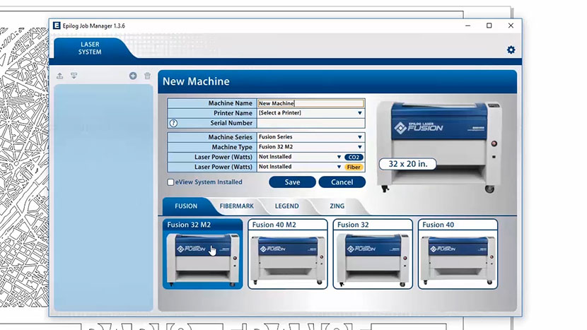
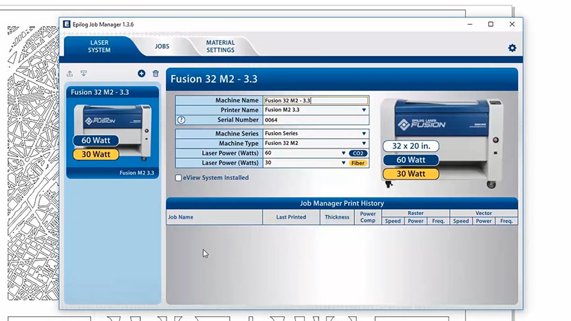
You will need to activate your laser system to get started. Click the correct tab for your laser, then your system. You can activate multiple machines if you have more than one laser.

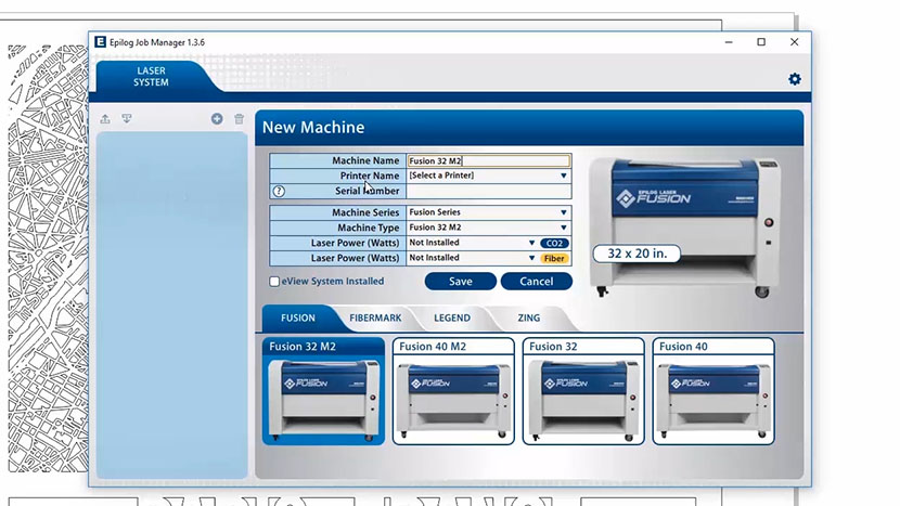
To activate your machine, start by giving your machine a name. Choose your laser from the dropdown list of printers. This is very important. If you do not choose the correct printer, you will not be able to print to the Epilog Job Manager.

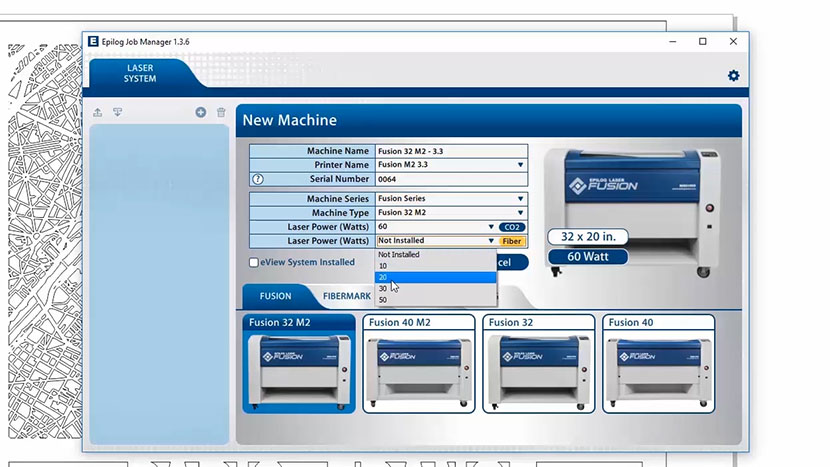
Select the correct machine series, machine type, and laser power. The laser power is very important because it is the setting the Job Manager will use to automatically load the proper material settings database files for your specific wattage of laser.

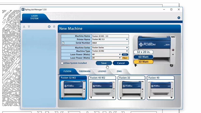
Then click the save button.

Your new laser has been activated in the Job Manager and appears in the left panel.

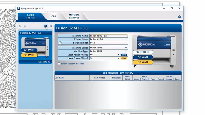
Use the Add or Delete keys to add additional machines or to remove a laser. The Job Manager is now ready to accept jobs from the Print Driver.

Printing to the Epilog Job Manager

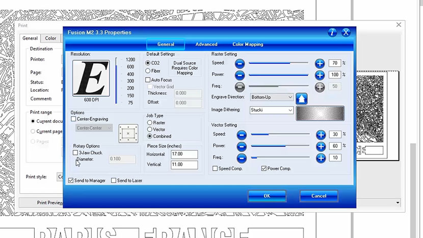
Create a file in your graphics software, and set your laser parameters in the print driver.

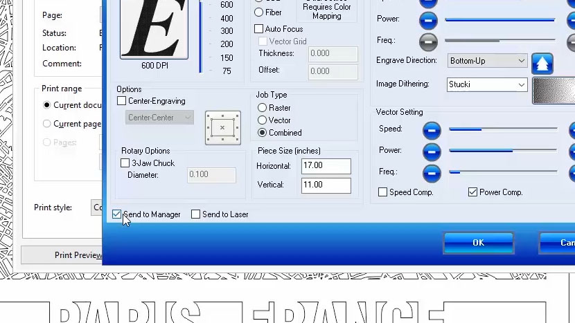
In the print driver, you’ll see a selection available under Rotary Options. You can choose to print to your laser system, the Job Manager, or both. This allows you to send your job to the Job Manager without sending it to the laser, so you can then print the job directly from the Job Manager at a later time, without accessing your graphics software.

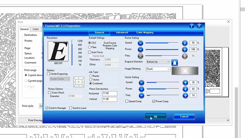
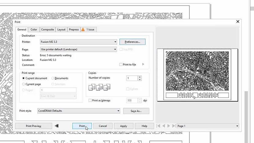
Once you’ve finished with your job settings, click OK, then click the Print button to send your job to the Job Manager.

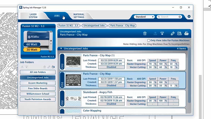
Now, click the Jobs tab. This is an easy way to set up an entire day’s worth of jobs all in one place.

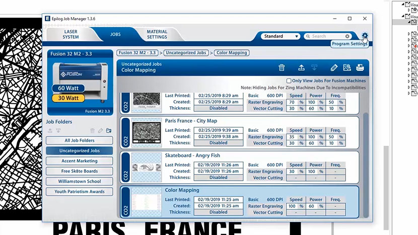
Organizing Your Print Jobs

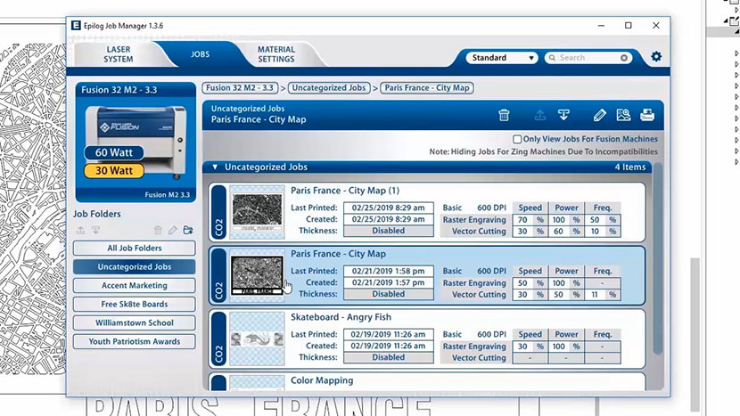
All of your new print jobs will be displayed in the Uncategorized folder. Click on your job to highlight it.

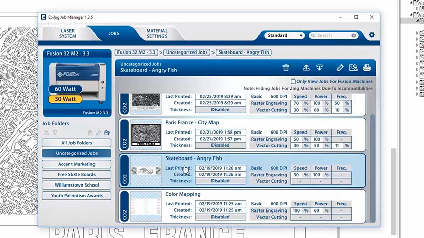
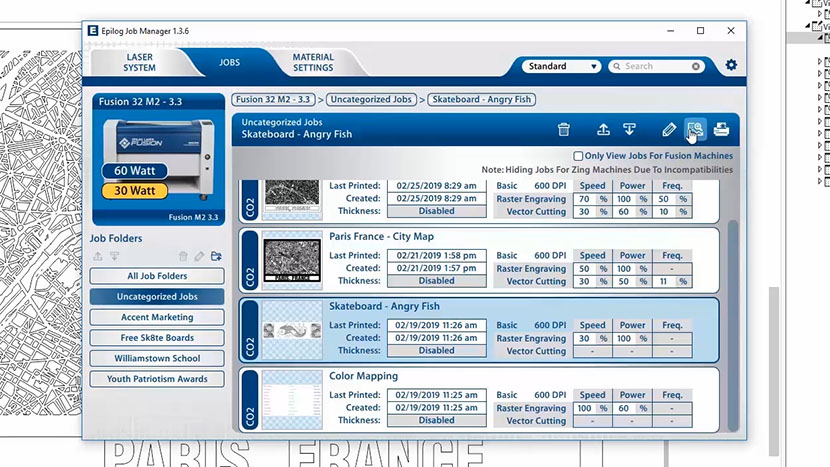
Now you’re able to Print, Edit, Preview, or Delete this job using the available icons.

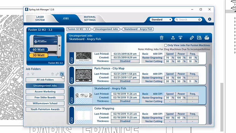
Creating and Deleting Folders

Click the Add Jobs Folder icon to add folders. You can add as many folders as you like, and organize the folders in any way you prefer.
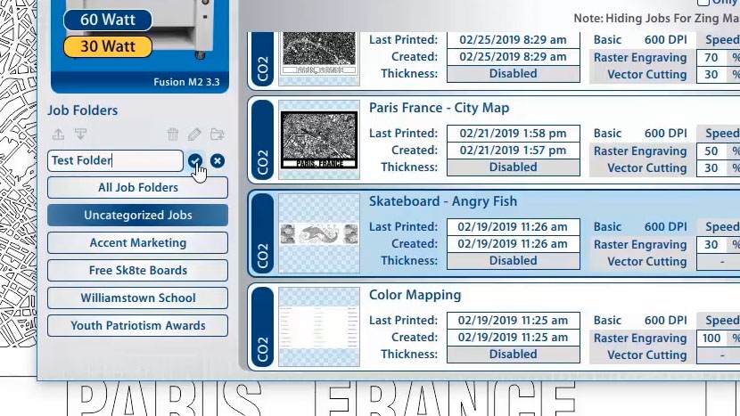
Creating Subfolders

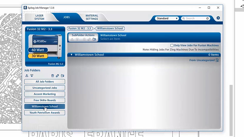
First, in the left panel, highlight the Job folder to which you want to add a subfolder.

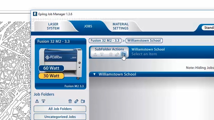
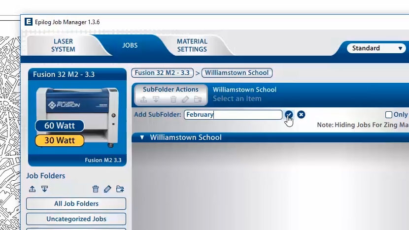
Now, click the Add Subfolder icon and type the name you’d like to use for the subfolder into the Add Subfolder field.

Then click the checkmark to create the subfolder.

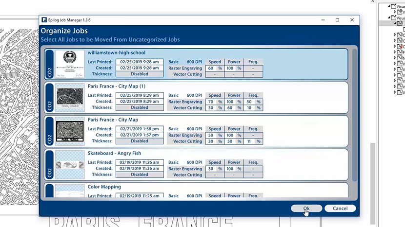
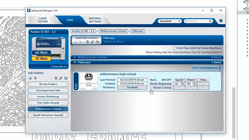
Moving an Uncategorized Job into a Subfolder

When you highlight a subfolder, you’ll see From Uncategorized at the bottom right side of the folder.

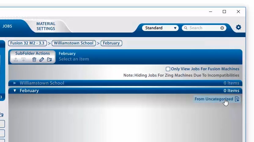
Click From Uncategorized to move a job from the Uncategorized folder to this subfolder. Select the job or jobs you want to move, then click the OK button to move the job(s) to the subfolder.

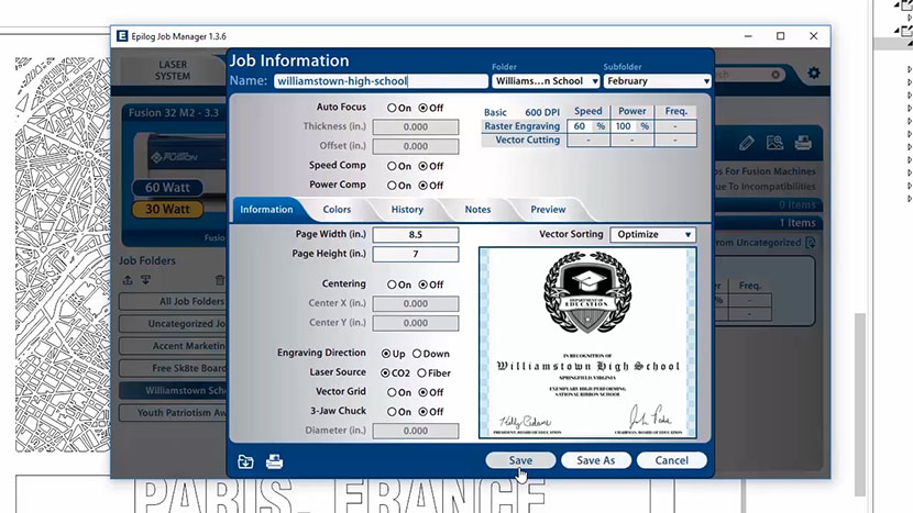
Moving Jobs Between Folders

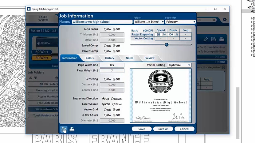
You can also move any job to another folder or subfolder in the Job Manager. Start by double clicking the job, then select the folder and subfolder from the dropdown menus at the top to choose where you’d like to save the job. You can now save the job with the same name, or save it with a new name. You can also modify the laser parameters and save them with the job.

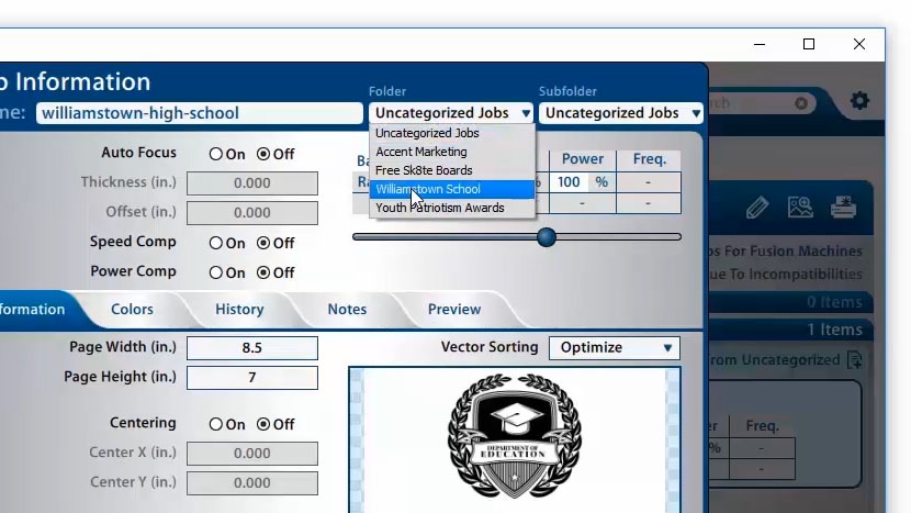
Once you’re finished, click Save to confirm.

Using the Material Settings Tab Configurations

The Material Settings tab stores all of the suggested laser parameters, like Speed, Power, and Frequency, for specific materials. Let’s look at how to load material settings for an existing job. These settings were loaded based on the wattage specified in the laser system tab when you set up your machine. To use the material settings that were automatically loaded into the Job Manager, go to the Jobs tab and double click on the job. Then click the Import button in the bottom left corner of the screen.

Navigate to the material settings you need by selecting the folder on the left, then the material setting in the main panel.

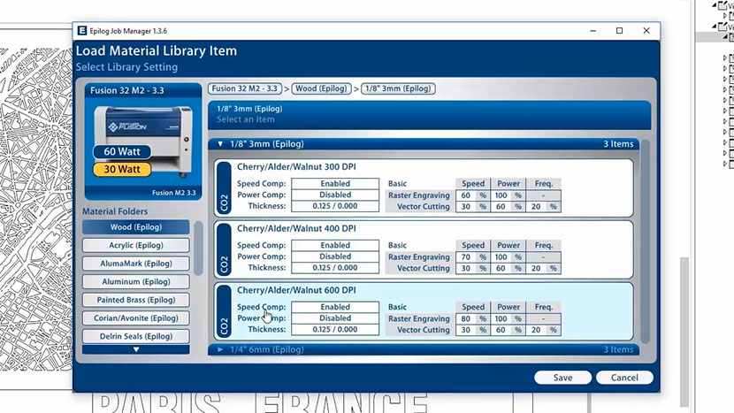
Then click the Save button.

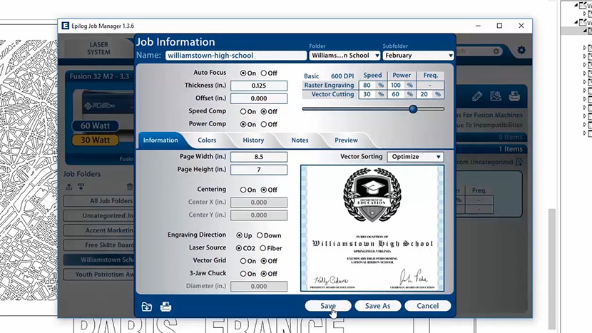
Your new settings have now been automatically applied to your job file. You can now save this file, save the file under a different name, or print this from the window.

Previewing Your Job

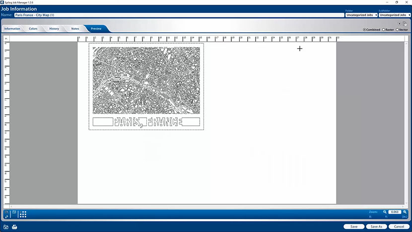
To view a preview of your Job, double click on the job in the Job tab, then click the Preview tab option.

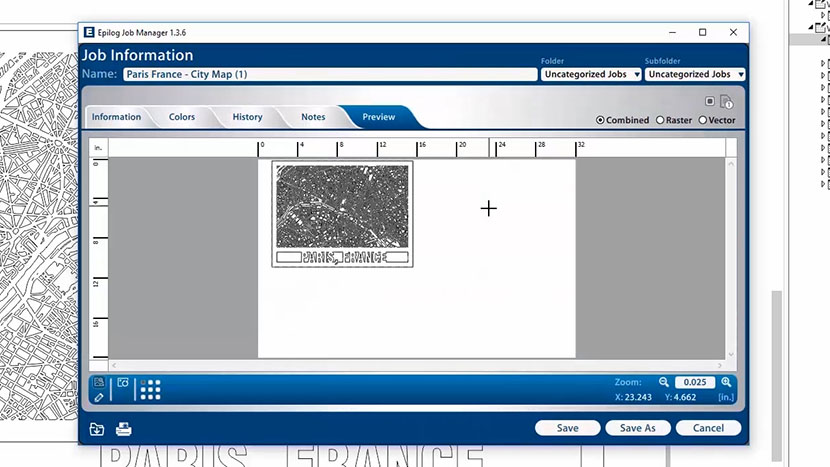
If you need to see a fullscreen version of your job, you can click on the Maximize button in the top right corner of the window.

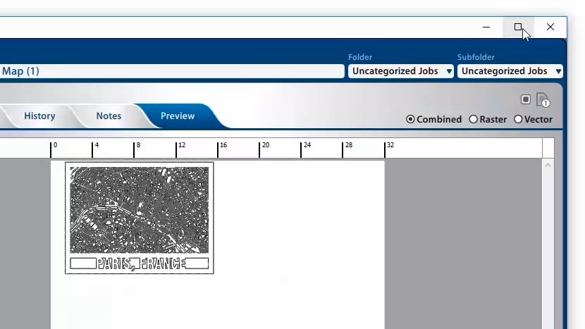
In the Preview panel, you can preview the Combined, Raster, or Vector components of your job by using the selection buttons at the top right corner of the panel.

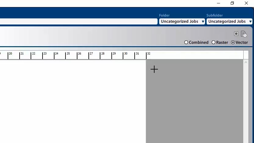
Selecting Raster or Vector will show only the Raster or Vector components of the job, respectively. Selecting Combined will show both Raster and Vector components. The preview mode is very useful in identifying unwanted vector components.

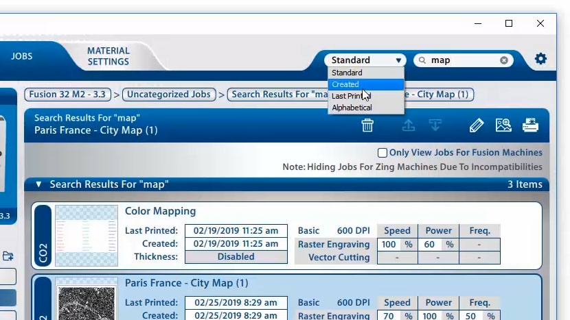
Using the Search Feature

The Job Manager comes equipped with a powerful search function. Simply type in part of a filename and press Enter to find all files containing a word or name.

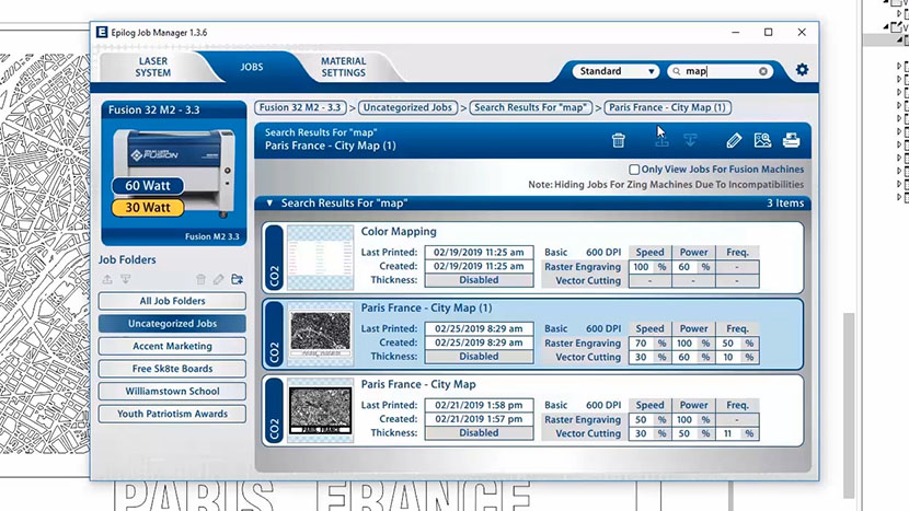
You can organize the search results by Standard, Created, Last Printed, or Alphabetically, which can be helpful when trying to find a specific file.

Job History

The Job Manager allows you to see a full print history of a job, including settings you used in each print. To access the history of a job, double click on the job, then select the History tab.

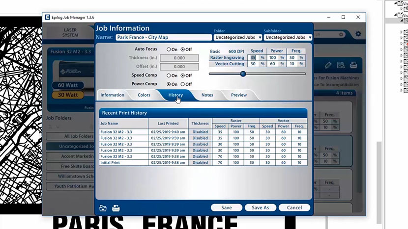
The History panel shows you the history of this job – what machine it was printed to, when it was first printed, all subsequent prints, and all laser parameters used. You can modify, print, or save from this panel using the listed settings or new settings. The new settings will be saved as the next print job, complete with timestamp and date.

Color Mapping

To access the color mapping settings used in a file, double click on the file to open the job information panel, then click the Colors tab.

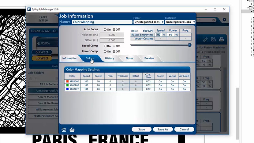
From this panel, you can modify color settings, save as a new job, save as the same job, print, or preview.

Changing Job Manager Settings

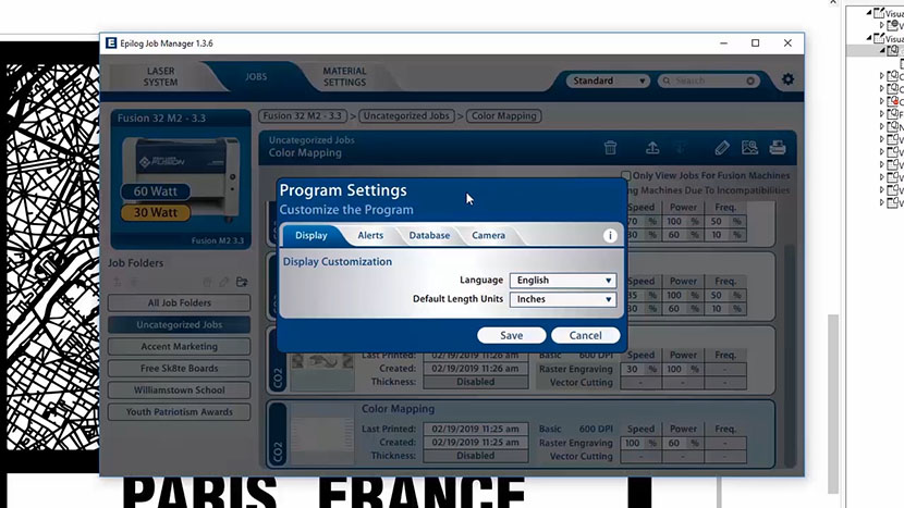
You can access the program settings by clicking on the gear at the top right of the window.

On this screen, you can set several different Job Manager settings. In the Display tab, you can choose from several Language options, and change the Default Length Units to Inches, Millimeters, or Centimeters.

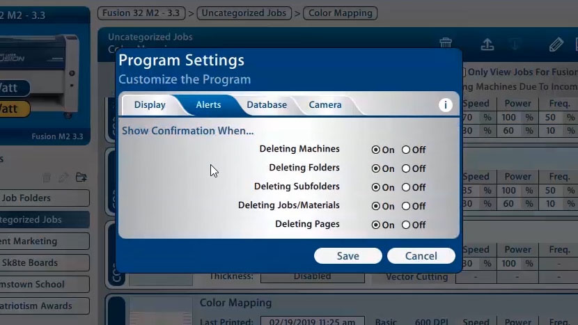
In the Alerts tab, you can activate or deactivate confirmation alerts for the deletion of machines, folders, subfolders, jobs, materials, and pages.

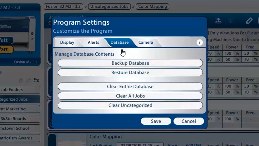
The Database tab allows you to create a database backup or restore a previous database. You can also clear the entire database, clear all jobs, or clear the Uncategorized folder.

We are constantly adding new features to the Job Manager. You can sign up for notifications at epiloglaser.com/register.
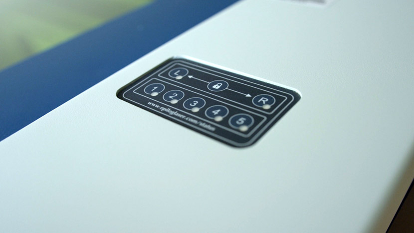
Print Driver Tour

General Tab

We’ll start on the General tab.

First, at the top left corner of the driver you’ll find the “Resolution” settings, which can be set from 75 to 1200 DPI. The higher you set the resolution, the higher your engraving quality will be. Typically you’ll use 400 or 600 DPI for most materials you engrave.

The Resolution settings in the Epilog Fusion print driver.

Next, choose between CO2 or Fiber lasers depending on which you have installed or which materials you want to process.

The CO2 and Fiber laser settings in the Fusion print driver.

Click the Auto Focus box to enable automatic focusing on your machine. If you have your Vector Grid installed, click next to Vector Grid to change the table height taking into account the height of the vector grid. Next enter your material thickness and if you would like to offset the table, such as on a material like acrylic, you can enter this measurement here as well.

The Auto Focus settings in the Fusion print driver.

The “Job Type” area is where you choose between Raster, Vector, or Combined modes, which includes both engraving and cutting within the same job.

The Job Type settings in the Epilog Fusion print driver.

The “Piece Size” setting is where you will set your page size dimensions to match the page size of your design.

The Piece Size settings in the Epilog Fusion print driver.

In the “Raster Setting” area you’ll set your speed and power settings, from 1 to 100%. You can find suggested speeds and powers for different materials in your manual. The frequency setting will only be active when Fiber is selected as your laser type. This refers to the pulsing of the fiber laser as well as the average output power per laser pulse.

The Raster Settings in the Epilog Fusion print driver.

The “Engrave Direction” setting can be set to Top-Down or Bottom-Up by clicking the arrow button or using the drop-down menu.

The Engrave Direction setting in the Epilog Fusion print driver.

The “Image Dithering” setting is a drop-down menu where you can choose between different ways for the laser to interpret the dot pattern in your file. There are three clipart modes: Standard, Brighten, and Low Res when running lower resolution images. The next three modes, Floyd Steinberg, Jarvis, and Stucki are all used for different types of photographs.

The Image Dithering setting in the Epilog Fusion print driver.

Next, you can set your Vector settings. Start with your speed and power settings, setting each from 1 to 100%.

The Vector Settings in the Epilog Fusion print driver.

The Vector cutting frequency ranges from 1 to 100. This is the pulse rate of the laser as it cuts. A low frequency will produce a dotted line, often used for scoring paper, while a high frequency, where the laser beam is on continuously, is often used for cutting acrylic to create a flame polished edge.

The Vector cutting frequency setting in the Epilog FiberMark print driver.

The Speed Comp check box reduces all speed settings by one half. For example, a speed setting of 10 without speed comp selected will move twice as fast as a setting of 10 with speed comp turned on. This is most often used when cutting thicker materials at very low speeds, allowing you to cut through thicker materials in a single pass.

The Speed Comp checkbox in the Fusion print driver.

When checked Power Comp reduces the laser output when the laser carriage slows as it moves through a curve. Consider it a slow cutting option. Selecting Power Comp is especially useful for vector cutting jobs that incorporate a large number of curves. Most users find that keeping Power Comp selected is the preferred setting.

The Power Comp checkbox in the Fusion print driver.

Under the Options section of driver you’ll find Center-Engraving. The Center-Engraving checkbox will enable the center-engraving features of the laser. Choose your new home position and the laser will center your engraving at that position.
You can choose between left-center, top-center, page-center, and center-center positioning.

The Center-Engraving setting in the Epilog FiberMark print driver.

Under Rotary Options, select the checkbox if you are using the 3-Jaw Chuck Rotary Attachment in the system. This is not necessary if you are using the standard Rim-Style Rotary Attachment. After selecting the check box, enter the diameter of your piece.

The Rotary Options in the Fusion print driver.

Then you can choose to send the project to the Job Manager for easy access later…

The 'Send to Laser' setting in the Epilog FiberMark print driver.

…or to send the job directly to the laser, or both.

The 'Send to Manager' setting in the Epilog FiberMark print driver.

Advanced Tab

Next, we’ll move on to the Advanced tab at the top of the screen.

The first area of this tab is the “Raster Type” setting. Typically you will be operating the laser in Basic mode.

The Basic Raster Type setting in the Fusion print driver.

3D mode changes how the laser looks at the grayscale images in your design, and will change the laser power applied to each dot, creating a 3D gradient effect on your material.

The 3D Raster Type setting in the Fusion print driver.

Stamp mode is used to enable the laser’s rubber stamp settings.

The Stamp Raster Type setting in the Fusion print driver.

Under “Stamp Settings”, the Shoulder setting adjusts the angle of the sides of the stamp.

The Shoulder Stamp Setting in the Epilog Fusion print driver.

The “Widening” setting adjusts the boldness of the characters.

The Widening Stamp Setting in the Epilog Fusion print driver.

Selecting the “Mirror” checkbox automatically inverts the artwork for you.

The Mirror Stamp Setting in the EPilog Fusion print driver.

Selecting the “Fence” checkbox tells the laser you have created an outer border on each stamp on the sheet.

The Fence Stamp Setting in the Epilog Fusion print driver.

When you receive a notification of a firmware update on your system, select the “Update Firmware” checkbox, then load the file to start the firmware installation process.

The Update Firmware section of the Epilog Fusion print driver.

Under Language, you can change the language displayed on the print driver.

The Language drop-down in the Epilog Fusion print driver.

For users that prefer the Legacy print driver Epilog has provided, select the “Classic UI” checkbox.

The Classic UI checkbox in the Epilog Fusion print driver.

The “Configurations” area of the driver allows you to save and access material and job settings. When your settings are perfect for a project, save them for the next time you need to run that job. You can also load our suggested material settings for materials into the driver from the driver download page on our website.

The Configurations settings in the Fusion print driver.

Color Mapping Tab

Finally, we’ll look at the “Color Mapping” Tab at the top.

Color Mapping lets you set different speeds and powers to different colors within your artwork. Click the checkbox to enable the “Color Mapping” settings.

The Color Mapping checkbox in the Epilog Fusion print driver.

Change the speed, power, frequency, focus and offset for each color and whether to activate in raster, vector, or combined mode.

The laser settings section of the Color Mapping tab in the Epilog Fusion print driver.

When you’re done adjusting your settings, click the right arrow to apply your new settings.

The right arrow button in the Color Mapping tab.

This was a basic overview of the Epilog Fusion M2 print driver. When you’re done adjusting your settings, click the OK button to print the job to the laser or to send it to the Job Manager.

Machine Tour

Control Panel

The keypad on the Fusion M2 operates as the control panel for your machine. The joystick and touch button controls allow you to access your jobs, start and stop the laser, focus the system for your project, and much more. The LCD panel displays the current jobs at the machine. Scroll through the jobs to find the one you want to run. Use the joystick to jog and set a new home position, or even run the laser directly from the joystick to square off pieces of material.

You’ll also find the system status lights on top of the system, used for system diagnosis.

Cutting and Engraving Tables

Here is the optional vector cutting table for the Fusion M2 32 and 40. This robust table with metal honey-comb grid allows you to cut through all kinds of materials with minimal backside burning. The cutting table can easily be removed to access the engraving plate for your engraving jobs. When you’re not vector cutting, the engraving task plate provides a level flat surface for optimal engraving quality across the entire work area of your laser system. The work area includes to two linear rulers that help with placement of your objects at the top left corner of the engraving table.

X-Axis Assembly

This is the I-Beam, or X-Axis Assembly. It will initially be parked in the upper location of your work area, so you have better access to the laser bed to place items on the table.

Lens Assembly

The laser’s lens assembly is carried on the I-Beam which moves left and right in a sweeping motion in the x-axis direction, and moves the lens carriage in the y-axis direction as well.

On the lens assembly you will find the industrial-grade mirrors, lens, auto-focus, and air assist tube. The mirrors and lens are rated to over 500 watts and are integral part of Epilog’s optics system. It consists of a mirror that reflects the laser beam down through a focal length lens. Keeping your laser optics clean will help them perform their best, and it starts with front-mounted mirrors that can be easily removed for cleaning.

Air Assist

This is the Air Assist Tube, which directs a constant stream of compressed air along the cutting surface, reducing the possibility of flaming, scorching or charring when cutting through materials. The Air Assist Tube must be used in conjunction with a standard compressed air supply, or the optional stand-alone compressor offered by Epilog.

Front of the Machine

On the front of the Fusion M2 machines you’ll find the front access drop-down door. This safety-interlocked door allows you to easily place a tray of jigged parts and larger items on the table through the front of the system.

You’ll also find the power switch and emergency stop button.

Exhaust

At the back of the laser system you will find the Exhaust Plenum. The top five slots within the work area cabinet are where the engraving area will be exhausted of all of the smoke, dust and debris resulting from your engraving and cutting. The bottom four holes in the tray below the cutting and engraving plates operate as a vacuum suction table, pulling the air through the bottom of the cutting table away from the surface of your engraving material.

System Rear

Moving on to the back of the laser system you will find two 4” Exhaust Plenum to which you’ll attach your exhaust fan or filtration system. Just to the right of the Exhaust Plenum is the anodized tag where you’ll find your serial number, which you will need if you find it necessary to contact technical support.

Also located on the back of the machine you’ll find the AC breaker and where your power cord is attached to the system. You’ll also see Ethernet and USB ports used to connect your laser system to a computer, and the Air Assist Tube plugin for your compressor pump.

The top panel can be removed for easy cleaning of the Exhaust Plenum. The heart of your laser system, the CO2 laser source, is located below the exhaust area, followed by the Fiber laser source. Which of these you see will depend on your product configuration.

Right Side of the Machine

As we remove the right side panel of the system, we can see the inner workings of the machine. Attached to the I Beam is the x-axis motor. You can also access the y-axis motor, the controller board, and power supply for the laser sources in your system.

Left Side of the Machine

On the left side of the machine, the first component you will see if you have a Fiber or dual source configuration is the Fiber laser head. The metal cylinder on the side of the system is the beam path for the Co2 laser beam and the Collimator for a better beam path across your engraving table. Here on the I-Beam you can see where the CO2 and Fiber lasers are combined in a dual source system.

This was a quick look at the inner workings of your Fusion M2 laser system. Now it’s time to start engraving!

Setting up the Exhaust

Exhaust Option 1: Exhaust Motor Blower

What we have here is a standard 2 Horsepower exhaust motor blower. It is very simple to set up.

Hook up the exhaust hose to the machine, using a quick clamp to secure the hose to the machine.

Then, connect the other end of the hose to the intake port on your motor blower.

Next, connect another exhaust hose to the out-take port of the blower and the other end to a wall vent or window.

This solution is the most cost-effective option, but will be noisier than the other two options.

Exhaust Option 2: Filtration System

Another option is to hook up your Fusion M2 laser to an internal filtration system.

Required exhaust flow rates for filtration systems might be lower than the 650 CFM we require for external exhaust, because the filtration system will be placed directly adjacent to the laser system and does not exhibit the air-flow losses typically found with direct exhaust fans.

Please contact your Epilog distributor to help you match an exhaust system to the Epilog Laser machine you are using.

The standalone filtration systems are ideal if you cannot run an exhaust line to the roof or are looking to travel with the laser.

These units typically use a HEPA/Carbon Charcoal filter to remove odor, dust, and smoke.

There are several manufacturers of these types of filtration units that your distributor can help you choose between.

Exhaust Option 3: Outdoor Exhaust Unit

What we have here is an ideal setup in an office environment for exhausting fumes from an Epilog Fusion M2.

We have our exhaust pipe mounted against the wall connected to the motor blower on the outside of the building to ventilate outdoors.

Coming off the back of the laser, we have the exhaust port attached to flexible metal piping.

You want to keep the flexible portion of the tubing as short as possible to reduce air turbulence and to increase air flow.

Above the flexible tubing, we connect to a single or double galvanized steel straight pipe, depending on your exhaust system requirements and set up.

Your local HVAC professional can help you with setting up the best solution for your specific needs.

We suggest putting the exhaust blower outside with an electrical switch near the machine to turn on and off the blower.

This provides you with the quietest, most efficient operation.

Image Resolution and How it Affects Engraving

How do you know which DPI setting is right for your project?

Print quality is often determined by the resolution of an image, and is one of the main variables to consider when laser engraving. Resolution is expressed in DPI or dots per inch and is determined by the number of lines or dots that are engraved for every inch of movement. Each horizontal line of dots the laser produces is referred to as a raster line. A higher resolution selected in the print driver will make the dots engrave closer together, and will produce a higher quality result.

Although resolution does play a big part in engraving quality, keep in mind that engraving resolution is only one factor in determining image quality. The focus, brightness, and contrast elements of an image can have greater influence on the look of the final engraving than resolution alone. If low-quality artwork is used, even the highest resolution setting in the print driver will not improve the engraving. Also, keep in mind that image quality is subjective. Engraving a project at 300 DPI may be just fine for some images and customers, while 600 DPI is required as the absolute minimum for others.

These 3 examples exhibit qualities that will not produce the best engraving results.

The first example is a photograph taken at an event where the overall light is too bright and includes a very hazy look.

The second example is a low resolution logo provided as a 72 DPI image, rather than as vector artwork or in a vector format. 72 DPI is too low a resolution for a logo engraving project. It’s best to receive logo artwork as a vector image when possible.

And the third example is of a photograph that is very dark and includes very little contrast. These three photos illustrate some of the image issues that cannot be fixed with resolution settings alone at the laser.

Now we’ll discuss a bit more about how DPI works at the laser. This diagram shows the concept of raster lines and dots-per-inch (DPI), and the difference in dot density between 75, 300, and 600 DPI. Each dot represent a laser pulse, and the arrows represent the change in direction of the optics assembly for each raster line. Note how sparse the dots are at 75 DPI, and how the dots are very close and overlapping at 600 DPI.

How Resolution Affects a Job’s Completion Time

Generally, the time it takes to complete an engraving job is significantly affected by resolution. The higher the resolution, the more time it will take to complete an engraving job. While a higher resolution setting does increase the time it takes to complete an engraving, it allows you to achieve greater depth in materials like wood and rubber without having to reduce the speed of the laser. High resolution is also ideal for highly detailed wood engraving, such as the Epilog Aztec Calendar, and rubber stamps, which typically include small typefaces, intricate details, and more depth in the recessed areas.

There will be times when your customer requests a large number of pieces, and it will be important to minimize the time spent completing the job, without sacrificing quality. Optimizing a projects DPI by selecting a lower resolution will help reduce engraving time and increase profits.

These tiger photo engravings on anodized aluminum show the quality difference at 300, 400, and 600 DPI. Out of these examples, you can see the 600 DPI engraving produced a high-quality engraving and took 2 min and 44 secs to complete. But, the 400 DPI result is nearly just as good, and only took 1:49 seconds to complete.

As an example, if a customer ordered 100 of these tiger cards, then completing the 100 cards at 600 DPI would take around 4 hrs and 35 minutes to be completed, but engraving the project at 400 DPI would allow you to complete the project in just over 3 hours.

Combining DPI and Dithering Pattern for More Time Savings

There are other techniques to save you time without sacrificing engraving quality. Your Epilog Laser machine includes dithering pattern options, which eliminate the perceivable dot pattern you see when engraving at lower resolutions with the Standard dithering option.

In this example, note the dot pattern in the engraving on the left and the absence of the perceivable dot pattern in the example on the right. Each of these engravings were produced using 300 DPI, and the time to complete them was the same, but the one on the left was engraved using the Standard dithering pattern, while the engraving of the right was completed with the Stucki Dithering pattern.

Utilizing Epilog’s Stucki Dithering setting and engraving at 300 DPI produces a high-quality result similar to the 600 DPI, and also provides a large time saving advantage.

Applying this combination of settings to the previous project example of engraving 100 tiger cards, the engraving project would take only 2 hours and 17 minutes to complete, further increasing the time savings and profitability of this project.

As a final example and to further illustrate how DPI effects engraving, we’ve used a 50-watt Helix to engrave a grayscale clip art image, with settings of 45 percent speed and 100 percent power. The only thing that changed between each engraving is the resolution.

When it comes to settings and the final results of a project it can come down to a matter of personal preference as to which resolution looks better, but these photos show the dramatic difference resolution can make, especially when engraving grayscale images.

Matching Resolution Settings to Your Material

We recommend consulting your manual or the included material settings installed with your machine driver and the Epilog Job Manager.

75-200 DPI

Resolution settings in this range are typically used for non-production purposes where you want to experiment with image engraving location, or if you want to quickly produce a rough draft engraving. A low resolution can also be useful when engraving products that don’t require much material to be removed during engraving, such as fabric.

300 DPI

300 DPI is a versatile sweet spot for laser engraving. This setting is useful when engraving materials such as wood, glass, marble, plastic and other items that don’t benefit from the engraved dots being close together.

400 DPI

This resolution value is ideal for many applications. It combines very good image quality with fast engraving times. Many users like 400 DPI for all of their work.

600 DPI

600 DPI provides fine detail, depth, or is useful when high-end results are required.

1200 DPI

1200 DPI resolution is used for projects that require the best engraving quality possible, when engraving extremely small fonts, or when depth of engraving is the goal.

Things to Remember

  • When it comes to settings and the look of the final result, personal preference is something to consider, but also try to minimize the time it takes to complete a project when possible.
  • When experimenting with new products and materials, make sure to have extras on hand for dialing in the best settings and results.
  • Be sure to consult your manual as a starting point for materials settings, and also utilize the epiloglaser.com website as a resource for additional product ideas and materials settings. We provide Sample Club articles monthly, and you can sign up to receive them at www.epiloglaser.com/resources/enews-signup.htm.