Setting Up Your Page
We’ll start by creating a new file in CorelDRAW.

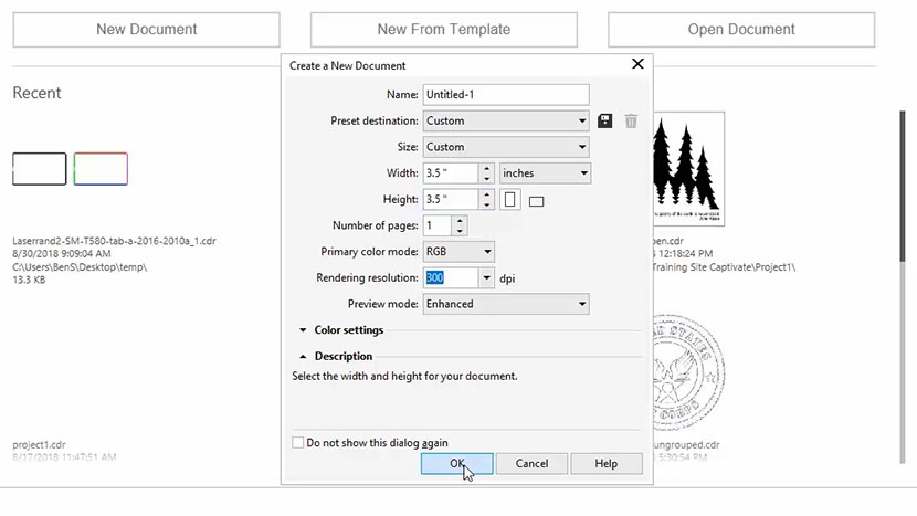
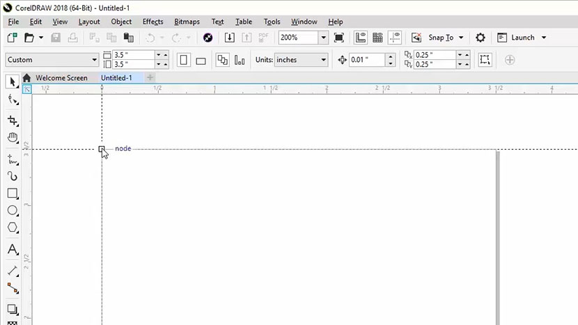
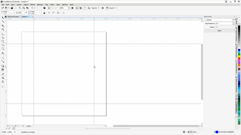
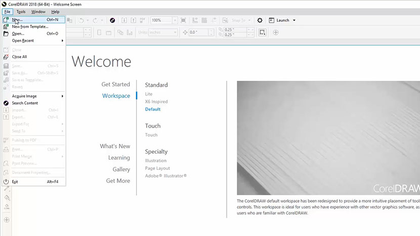
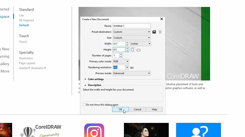
Click on the Get Started option on your Welcome screen, then click the New Document button. You can also use the shortcut keys Ctrl + N for opening a new document.
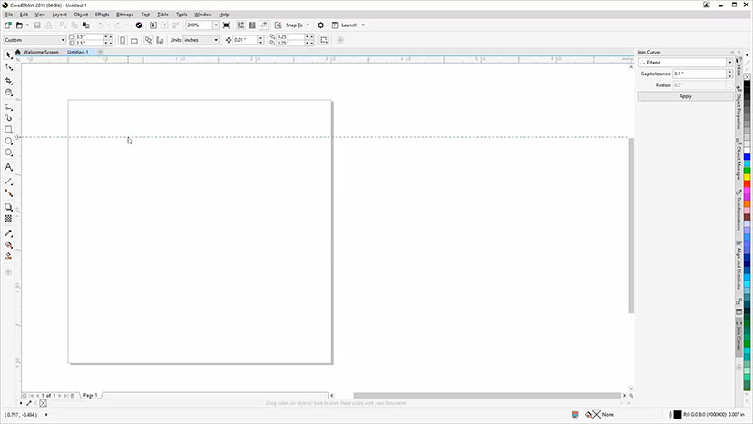
Now enter your page size. Enter 4” for the page width and 4” for the page height, then click OK.
Creating a Keychain Jig
For this project we’ll be engraving a wooden keychain, but first let’s create a cardboard jig to hold our keychain in place and reduce our setup time in the future.

To create a jig we need to create a hole the same size as the keychain so we can accurately place the keychain within the jig. Start by measuring the width of the keychain you received in your Training Suite packet. Use a set of calipers or a ruler to measure the keychain. The keychain should be 1.6”. We’ll use this later to set the diameter for the jig circle.
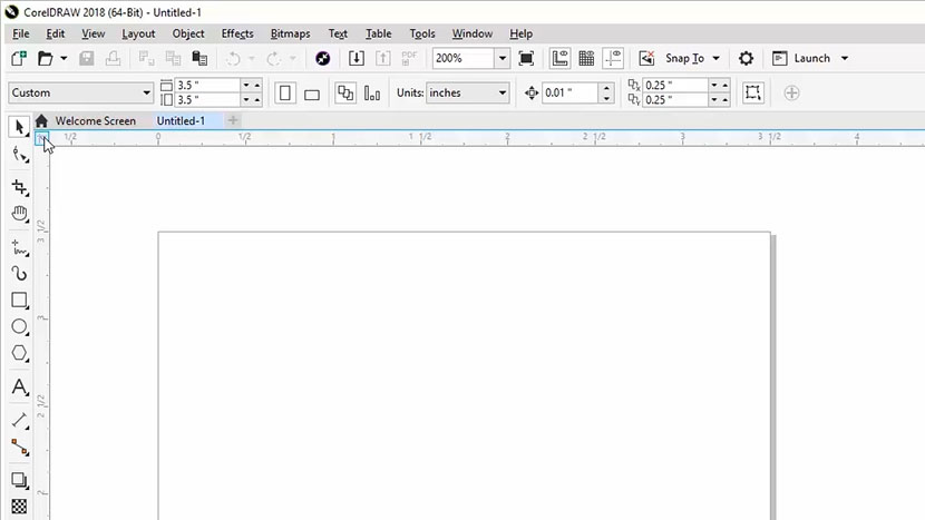
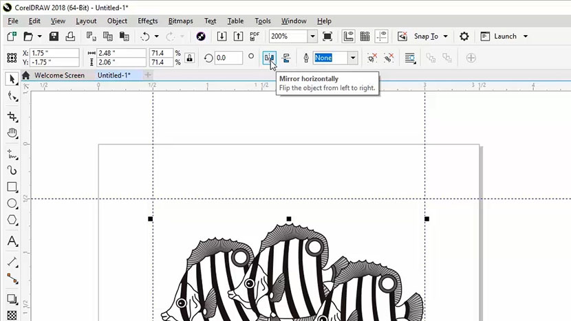
Now we’re going to draw a circle in CorelDRAW. Select the Ellipse tool in the toolbox on the left. While holding down the Ctrl key, click and drag across the page to create a circle. The size won’t matter as we are going to manually key in the width (diameter) for our jig circle.

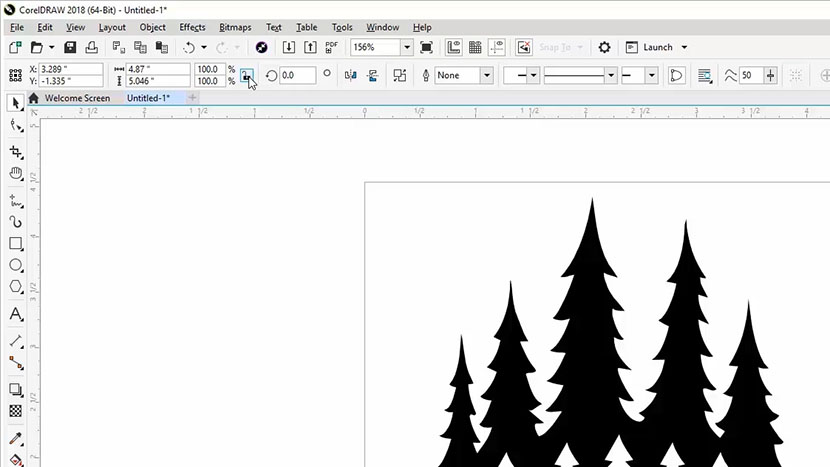
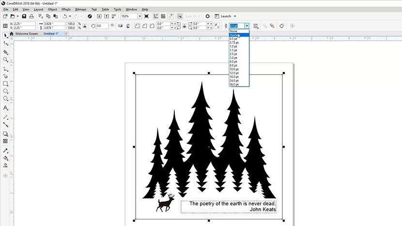
Once you’ve drawn your circle, click on the Lock Ratio button in the Properties bar at the top of the screen. Turning on the Lock Ratio option will make sure that the width and height of the circle are the same when we change the width in the following step.

Now enter the Width (diameter) of the keychain you measured earlier into the Object Size box at the top of the screen. We’ll enter 1.6” here, then press Enter key.

Now, we need a spot in the jig for the eyelet and ring to rest. Select the rectangle tool in the toolbox. We’ll need the rectangle to start about 0.25” above the circle and be about 0.25” wide.
Click and drag from above the circle down into the circle to create the cutout for the eyelet and ring.

If you prefer you can align the rectangle to the center of the page horizontally by selecting Object > Align and Distribute > Center to Page Horizontally.

Printing to the Laser (Jig Cutting)
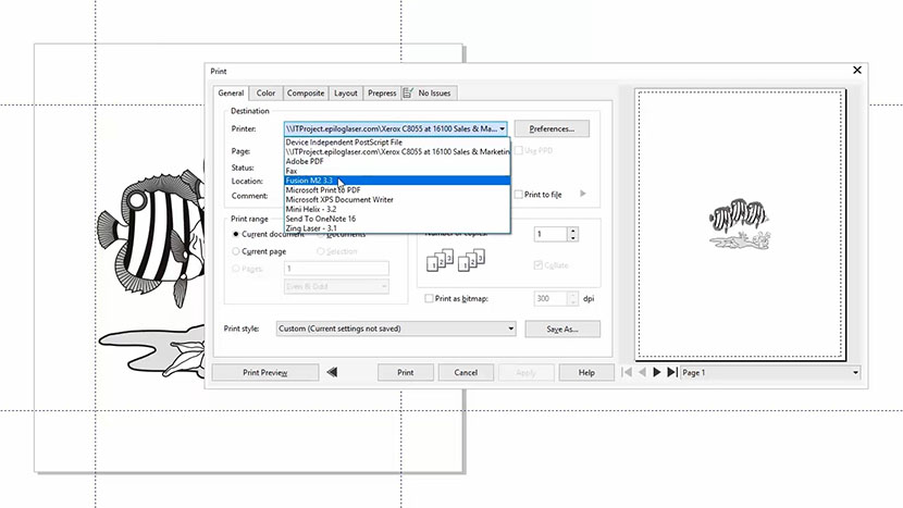
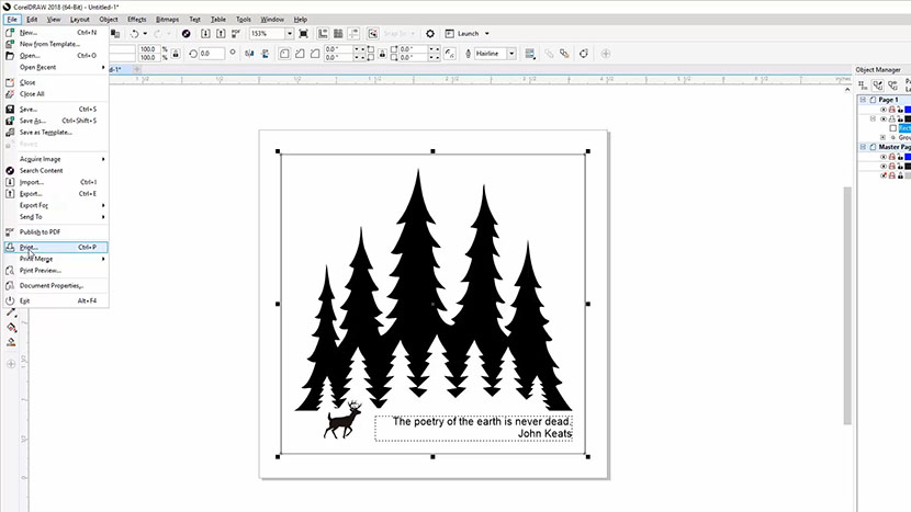
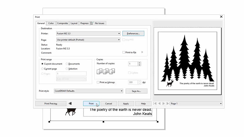
Now that we’ve completed the outline for our jig, we now want to print this file to the laser. Select File, then Print from the dropdown menu at the top of the screen. Select your Fusion laser from the printer options, and then click the Preferences button.

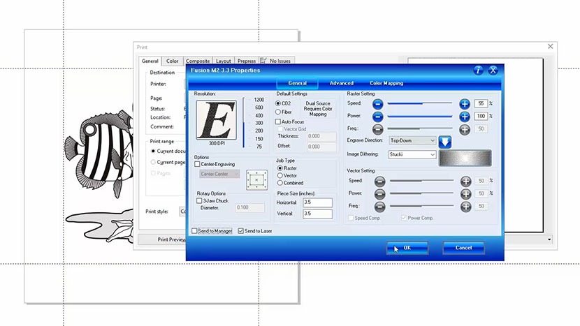
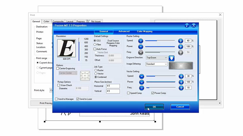
In the Laser Dashboard:
- Set the Job Type to Vector.
- Change the Piece Size to 4” x 4”.
- Set the Speed to 20%, Power to 100%, and Frequency to 10. (Refer to your laser manual for the suggested speed, power, and frequency settings for cutting cardboard with your wattage of laser.)
- Make sure Send to Laser is checked.
- Uncheck Send to Job Manager.
Then click the OK button.

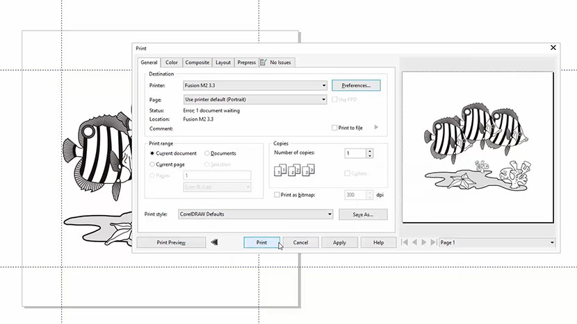
The print preview should now look like our Corel file.
Finally, click Print to send the job to the laser!

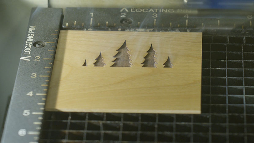
Cutting the Jig at the Laser
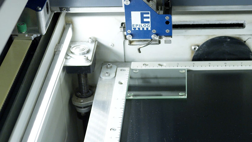
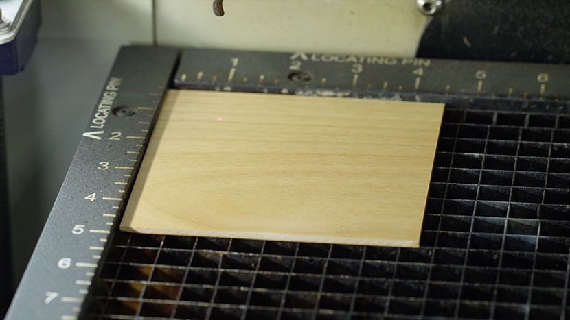
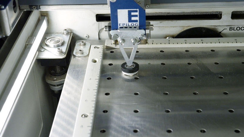
At the laser, position your piece of cardboard in the Home Position at the top-left corner of the work area.

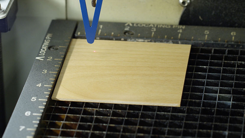
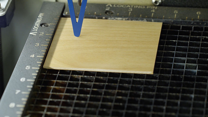
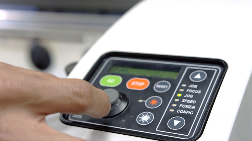
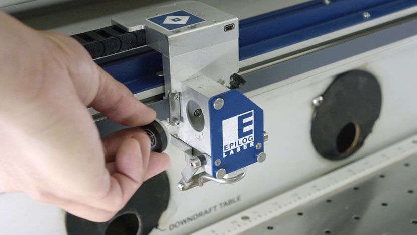
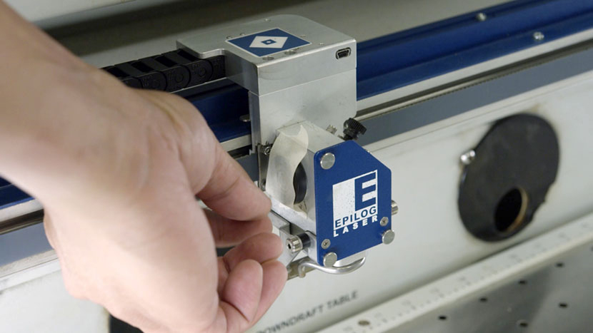
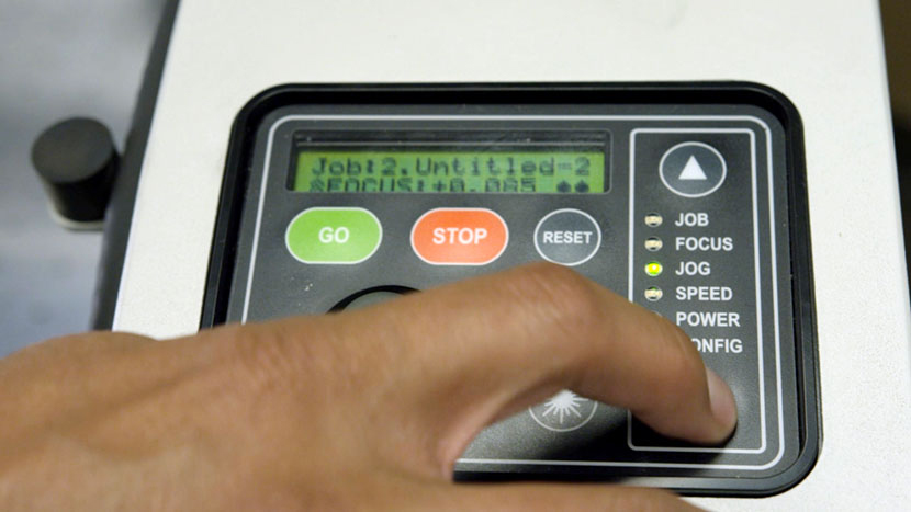
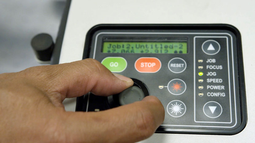
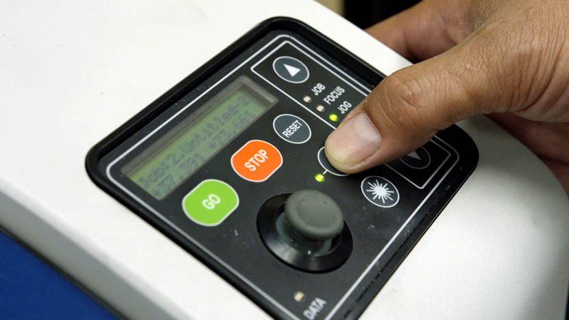
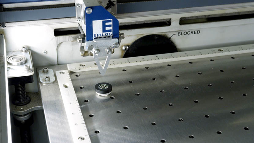
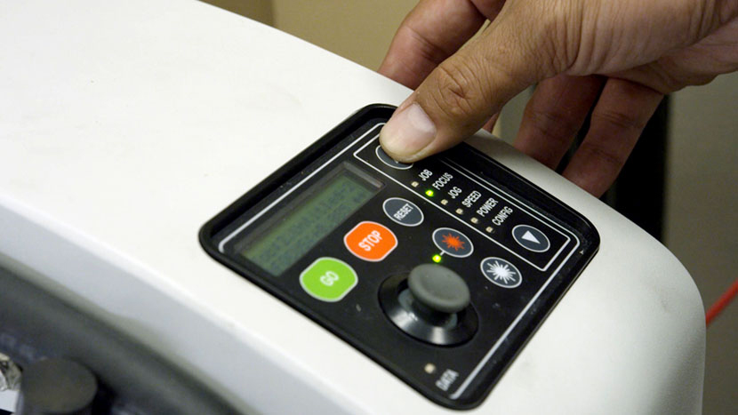
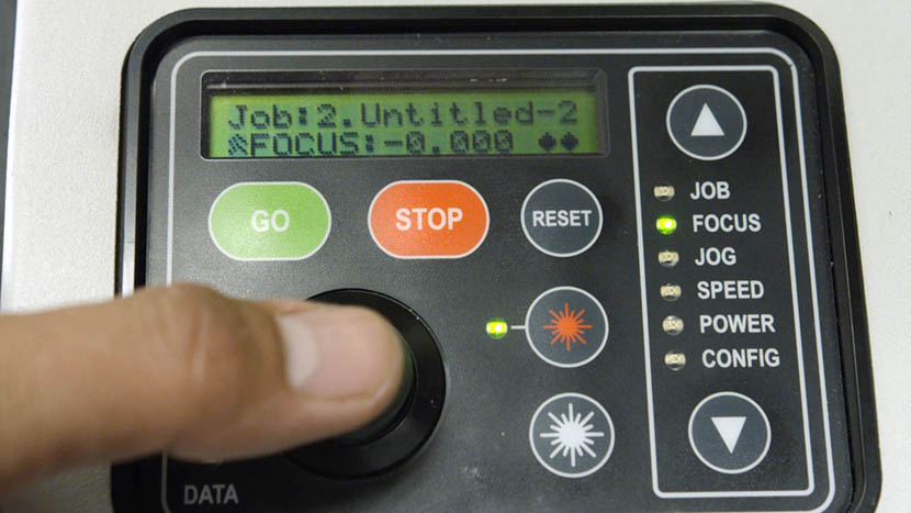
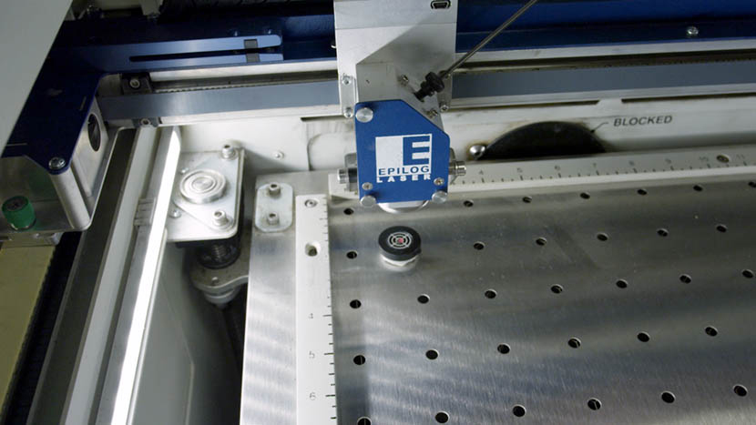
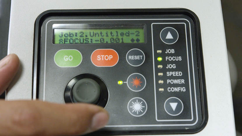
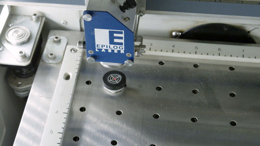
Hang your manual focus gauge on the optics assembly. Then select the Focus option on the keypad and press Up on the joystick to move the table up and bring the cardboard into focus. Once you’ve focused, remove the manual focus gauge and press the Reset button.

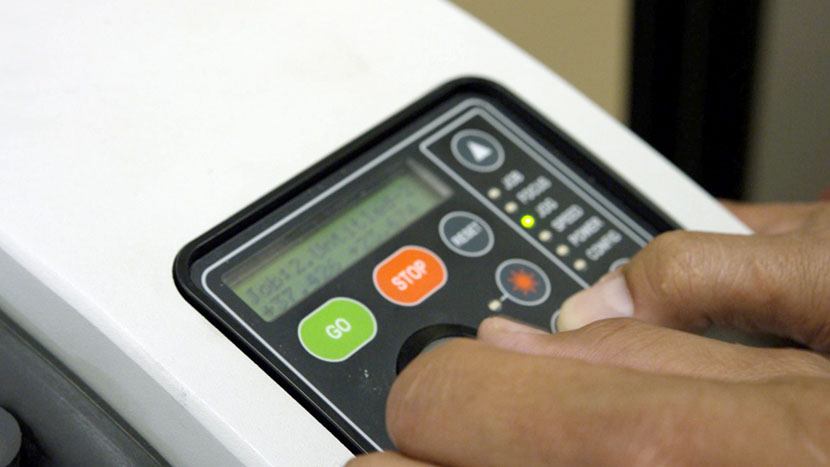
Now we’re ready to start the job. Press the Go button on the keypad to begin cutting your jig for the keychain engraving.

Importing Graphics
With the jig for the keychain cut, now it’s time to set up our graphic for the keychain. Keep your jig design open in CorelDRAW, as we are going to build from it and use the jig lines as a design template.
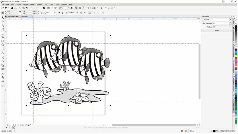
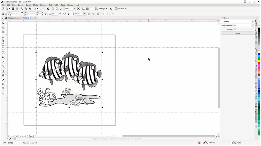
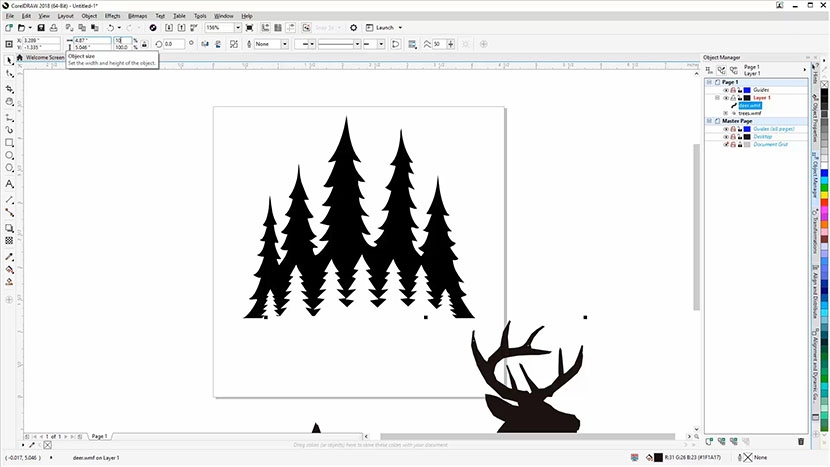
Now we’re going to import a graphic, resize it, and center the graphic to the jig circle for engraving on the wooden keychain. We’ll use a sea turtle graphic (sea-turtle.eps ) for this example, but you can use any graphic you prefer.
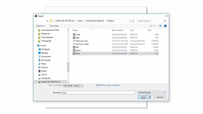
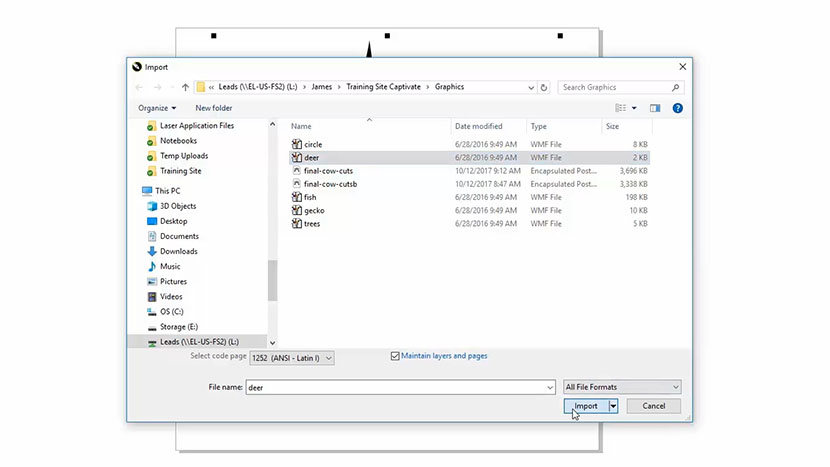
To import the file, select “File”, then “Import” from the drop-down menus at the top of the screen.

When the Import EPS options pop up you can leave the defaults as they are. Press the OK button to continue.

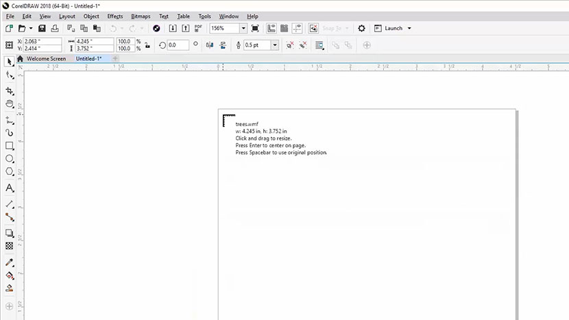
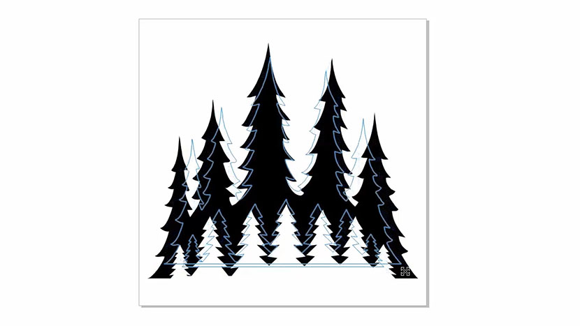
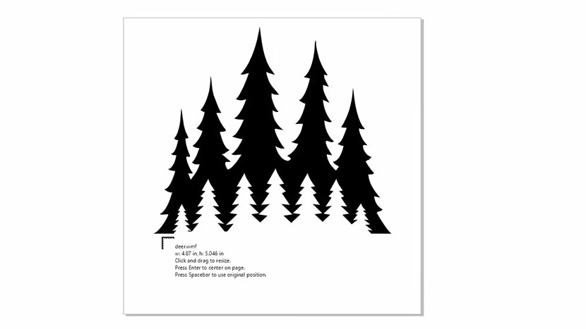
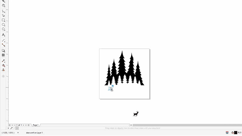
Now, click anywhere on the page to place the graphic in the work area.

Aligning and Resizing the Graphic
Now we need to align our turtle to the center of the circle and resize it to fit within the bounds.
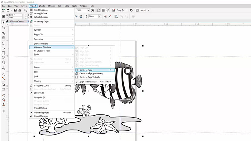
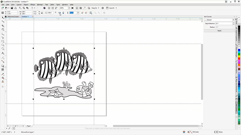
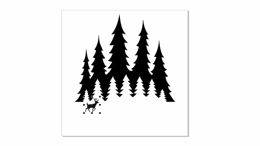
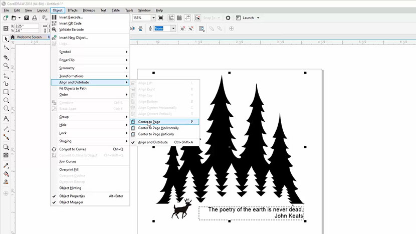
Make sure the object is still selected, then click Object from the drop-down menu at the top of the screen, then Align and Distribute, then Center to Page. You can also use the shortcut option of pressing the letter ‘P’ on your keyboard to center the image to your page.

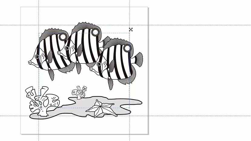
You’ll notice we have a little extra space to the bottom right of the turtle, so we’re going to click and drag the turtle down to the right a bit to visually center the turtle to the circle.

Printing to the Laser (Front Engraving)
With the graphic ready to go and still selected, we’re ready to print the graphic to the laser.
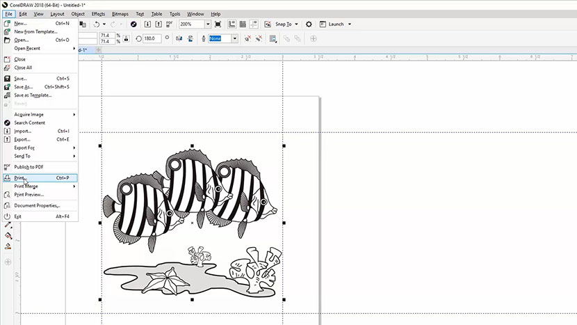
Select File, then Print from the dropdown menu, or press Ctrl + P on your keyboard.
Select your laser from the printer options.

Under Print Range, click Selection as the option. This setting will print only the graphic you had selected to the laser, and not the jig outline we are using as a template.

Then click the Preferences button.
In the Laser Dashboard:
- Set your Resolution to 600 dpi
- Select Raster from the Job Type options. (We’ll use Raster since we’re only engraving this file, not cutting.)
- Set the Speed to 60% and Power to 100%. (Refer to your laser manual for the suggested speed, power, and frequency settings for cutting cardboard with your wattage of laser.)
- Select Bottom-Up for the Engraving Direction.
- Select Stucki as the Image Dithering pattern. (The Stucki setting will randomize the dot pattern in the graphic and give us a consistent look to our wood engraving.)
- Set the piece size to match your page size. Set the horizontal and vertical size to 4.00 inches.
- Make sure Send to Laser is checked.
- Uncheck Send to Job Manager.
Then click the OK button.

The print preview should now look like our Corel file.
Finally, click Print to send the job to the laser!

At the Laser (Front Engraving)
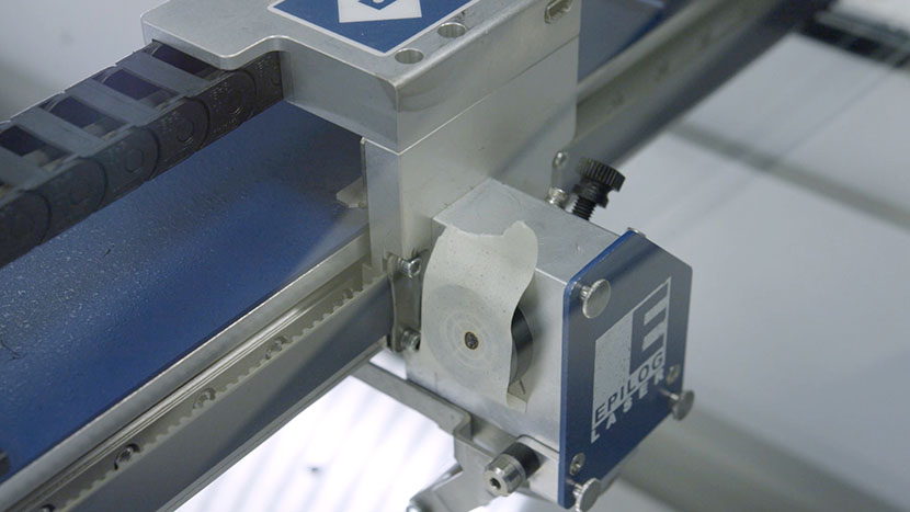
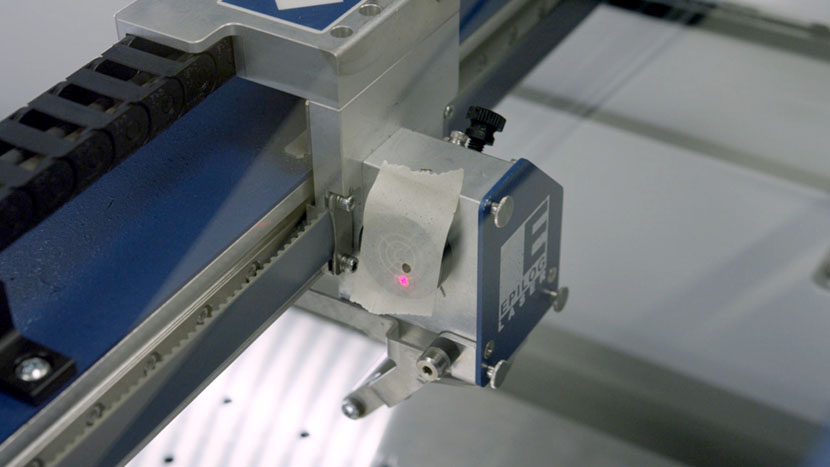
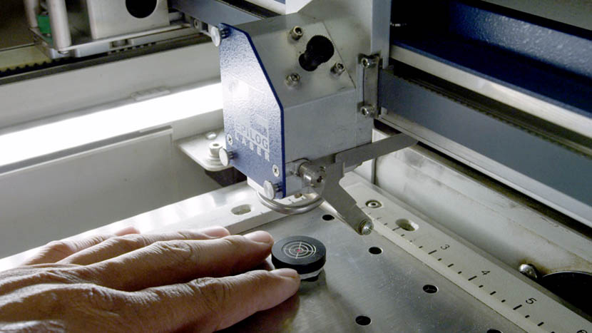
At the laser, we’ll place the keychain into our jig located in the top-left corner of our work area.

Hang your manual focus gauge on the optics assembly. Then select the Focus option on the keypad and press Up on the joystick to move the table up and bring the keychain into focus. Once you’ve focused, remove the manual focus gauge and press the Reset button.

Now we’re ready to start the job. Press the Go button on the keypad to begin your wood keychain engraving job.

Engraving the Backside with a Name
There are great time-saving advantages to using jigs when you need to engrave multiple items, or need to engrave on the backside of an item.
Let’s go ahead and engraving the backside of our keychain with a name to personalize the keychain for someone.
Flip the keychain over in the jig to get started.

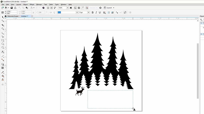
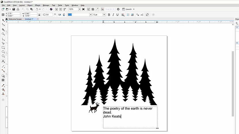
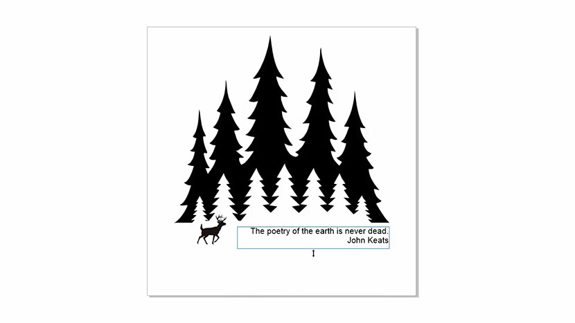
Back in CorelDRAW, we’re going to use the Text tool to add a name to our keychain. Select the text tool from the Toolbox options on the left side of your screen, and click anywhere on the page. Type out the name you would like to add to the keychain, and select the typeface you’d like to use for the name.

We’re going to use the name Charlotte in Birch Std (Standard) for our example.

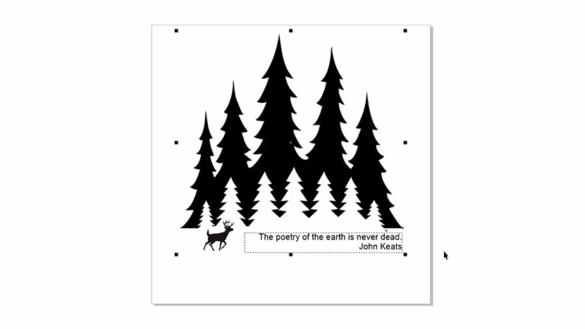
Once you’re finished typing out the name and selecting the typeface, click and drag the turtle outside of the page bounds, because we don’t want the turtle to be included in our next engraving.
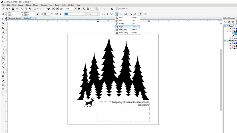
Then press the ‘P’ shortcut key on your keyboard to center the name to the page and the jig bounds.
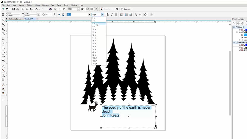
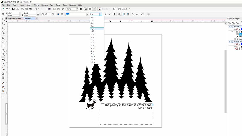
If you need to, resize the name to better fit it to the keychain’s engravable area. Remember to hold down the Shift key while resizing to keep the proportions of the text the same as you resize it.
Printing to the Laser (Back Engraving)
Since we’ve already engraved one side of the keychain, the engraving settings we used from the previous turtle engraving job will be saved in the Print Driver Dashboard settings. All we need to do now is hold Ctrl, then press ‘P’ on the keyboard, or you can click File, then Print from the menus at the top of the screen to print the file to the laser.

Make sure the preview only shows the text you’ve selected to print, then click the Print button.
At the Laser (Back Engraving)
We’ve already flipped our keychain over to engrave the backside, and the laser’s focus is already set.
Simply press the Go button on the laser to engrave the name.

And then you’re done!