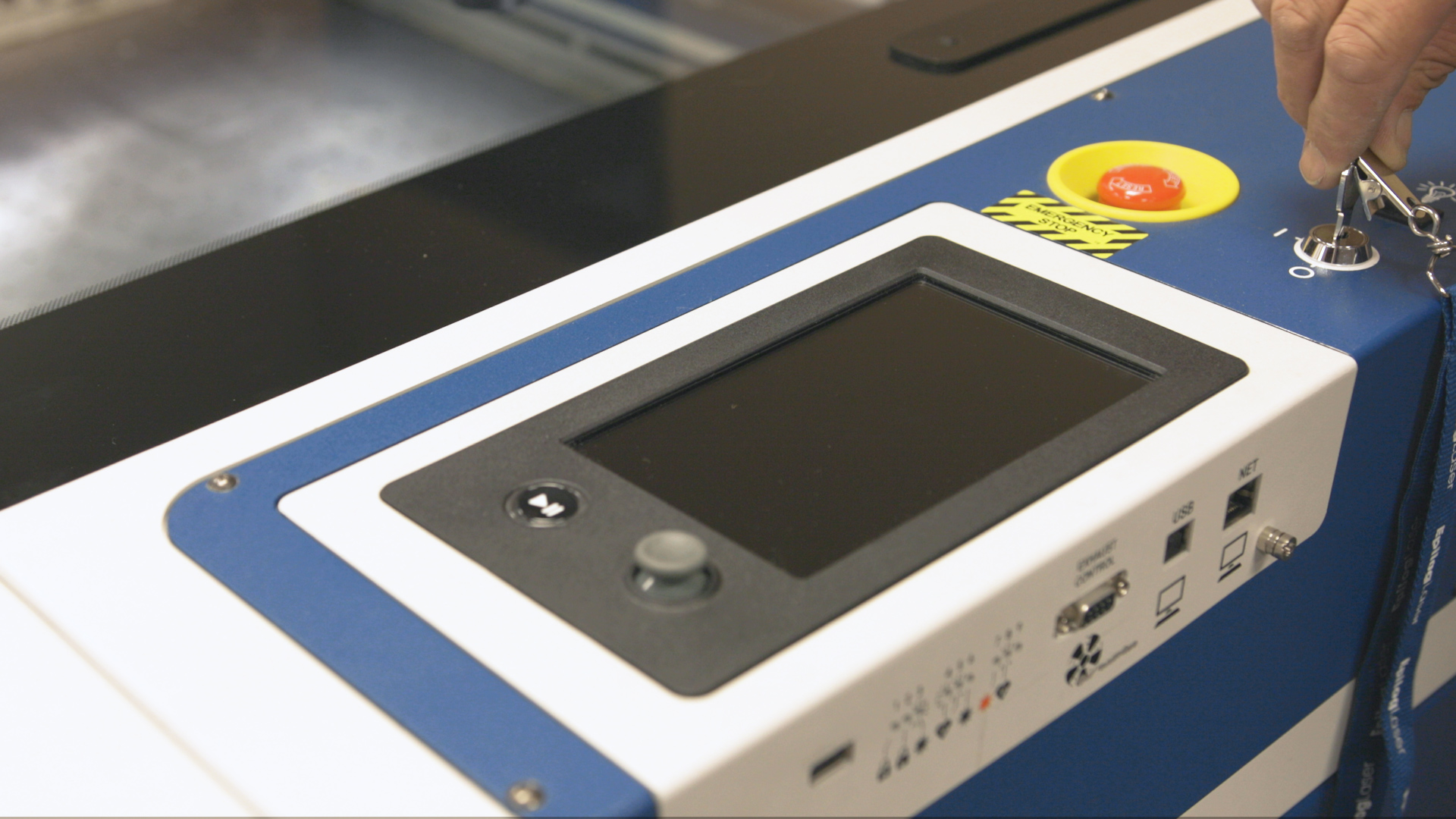
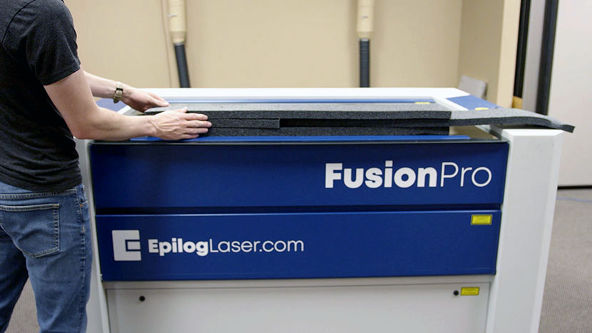
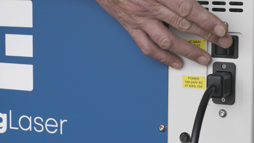
Turn On
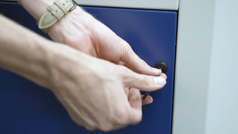
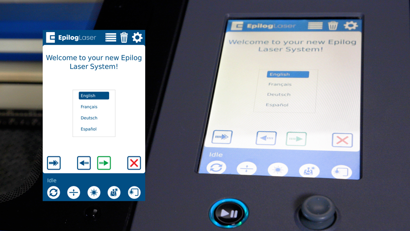
Power on the laser.
For the following procedures, the table will be broken into four (4) positions. Each position is identified by its relative distance to the laser source and corresponds with the mirror to adjust for that position.
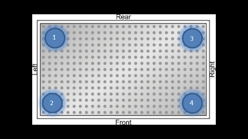
Three of the four adjustment mirrors used for alignment are on the left side of the engraver. The mirror numbers correspond directly with the positions on in the bed; for example, if the lens carriage is in Position #1 than you will only adjust Mirror #1.
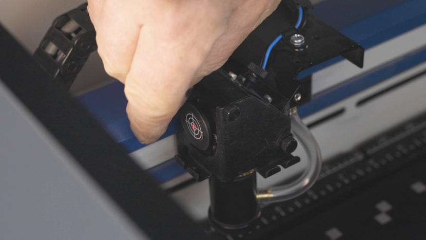
The final adjustable mirror is located on the carriage. The alignment process for the carriage mirror will be addressed last.
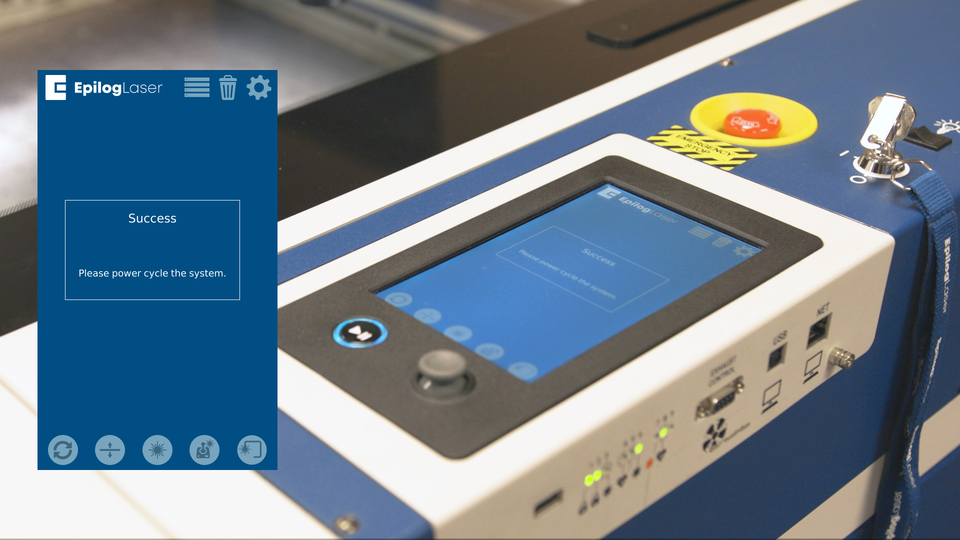
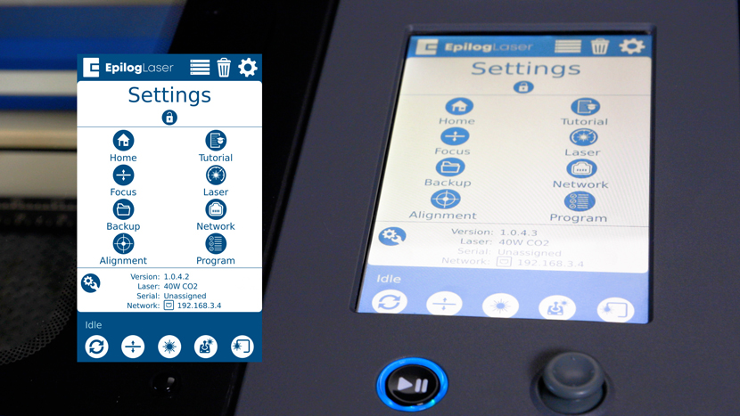
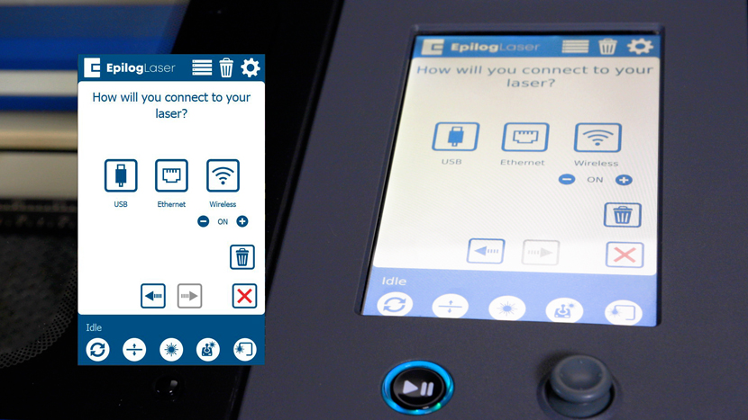
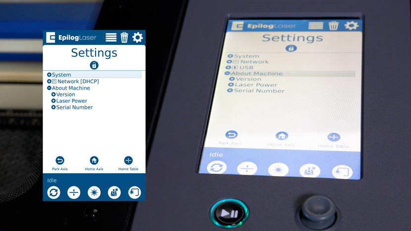
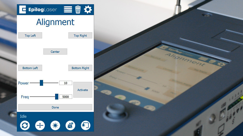
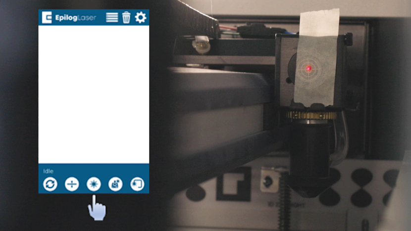
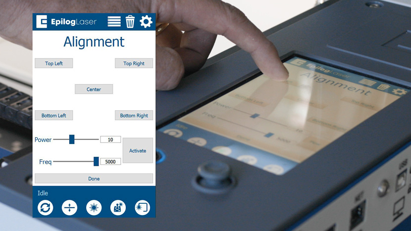
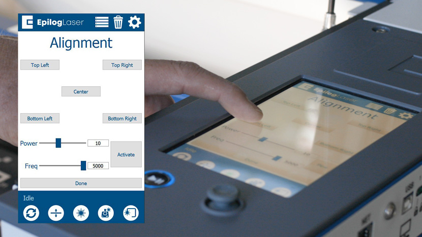
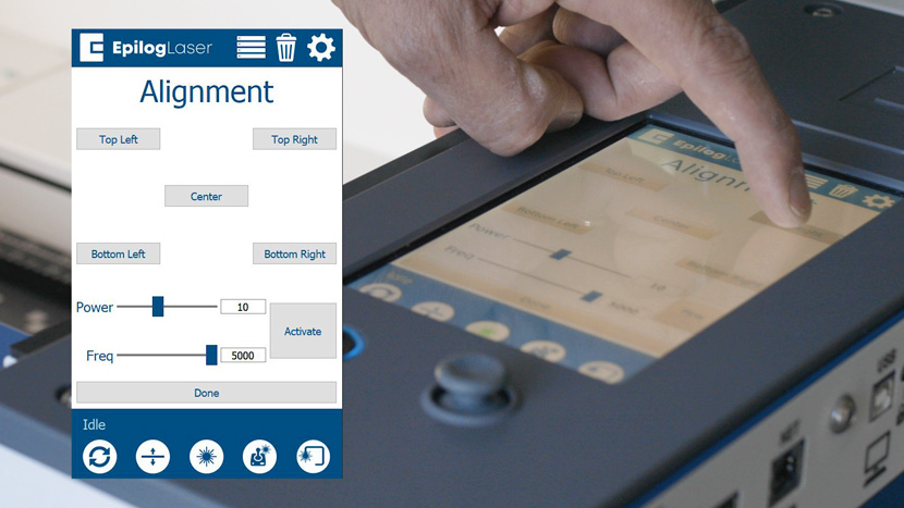
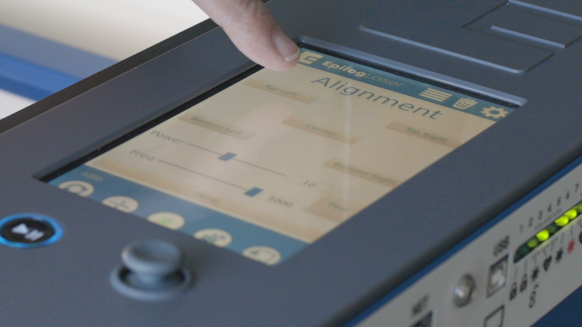
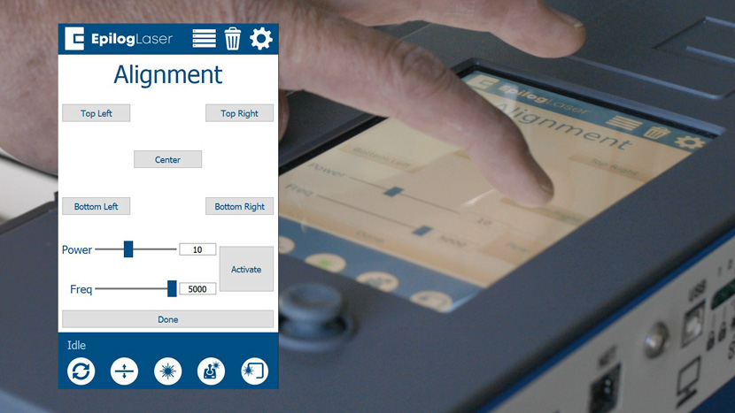
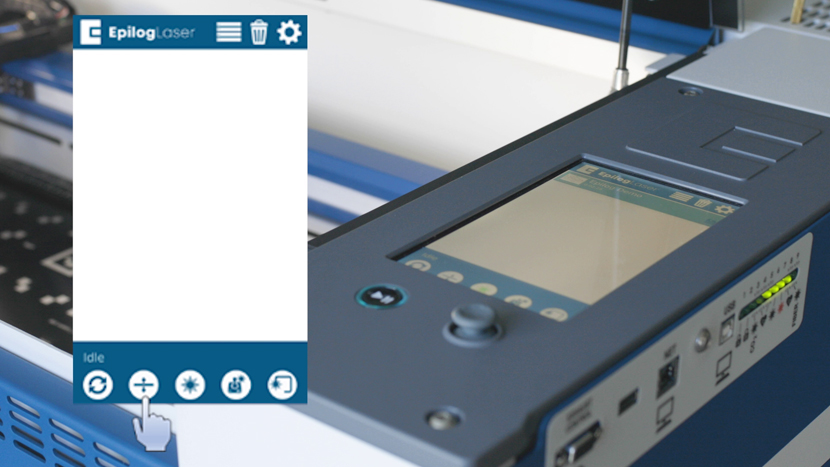
The Fusion Edge & Fusion Pro have an Alignment mode that may be accessed from the settings menu.
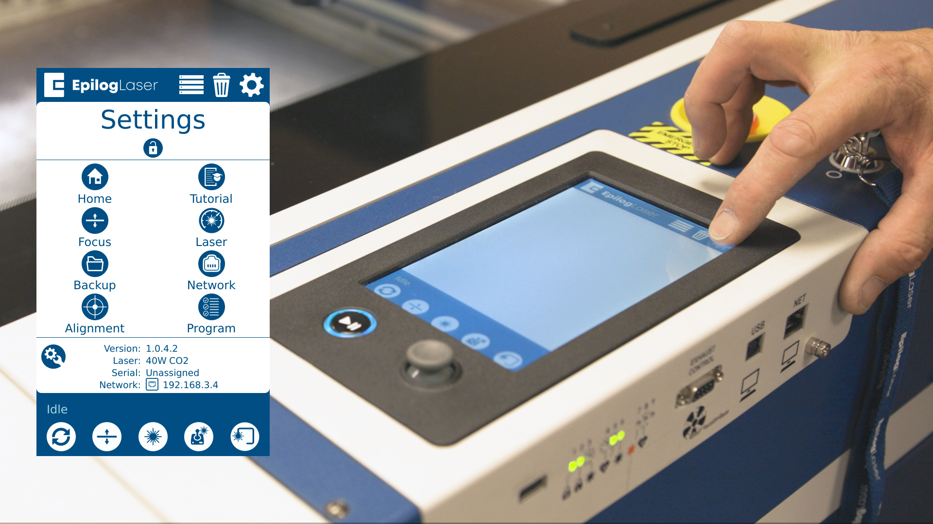
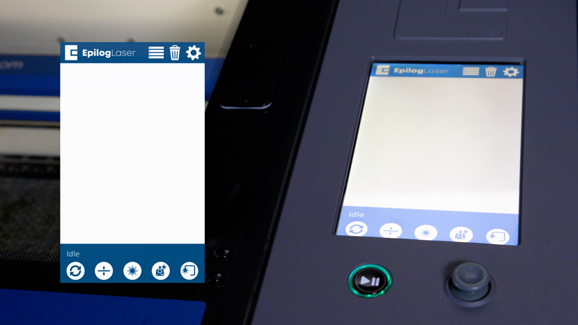
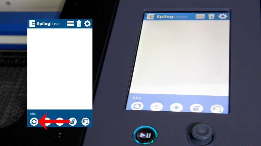
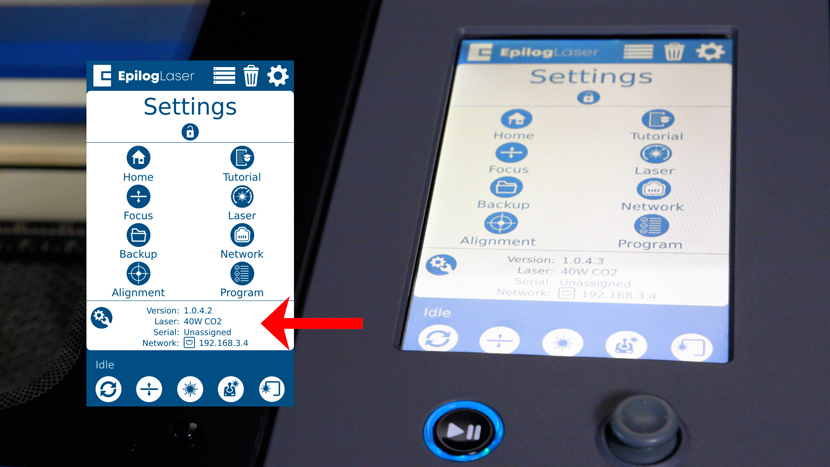
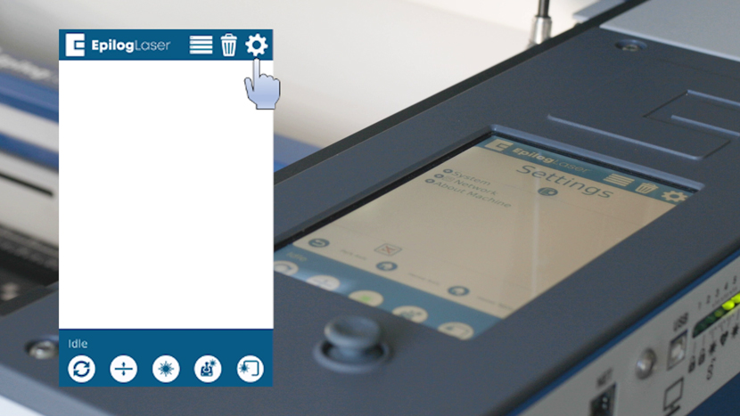
To access the Menu, tap the gear icon in the upper right corner of the touch screen.
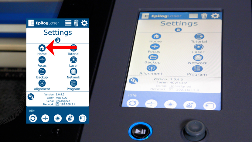
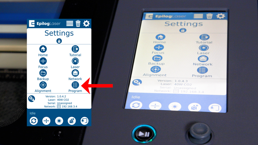
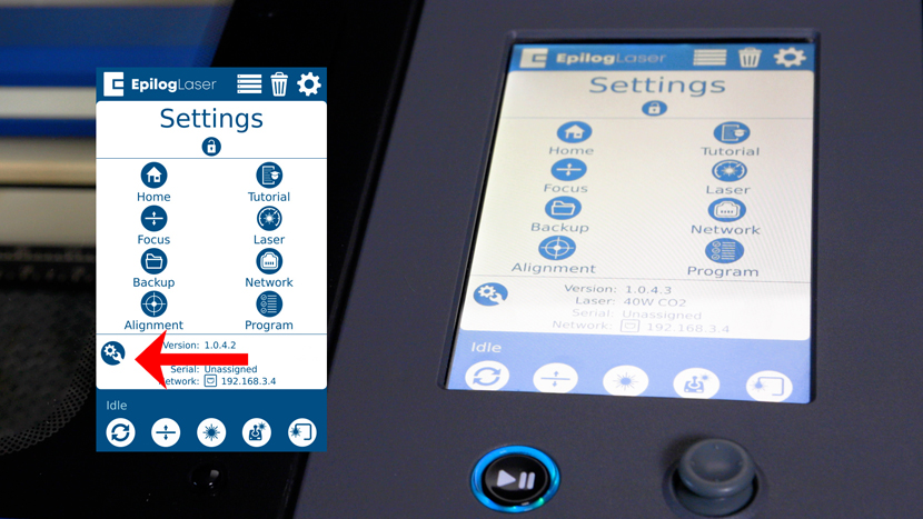
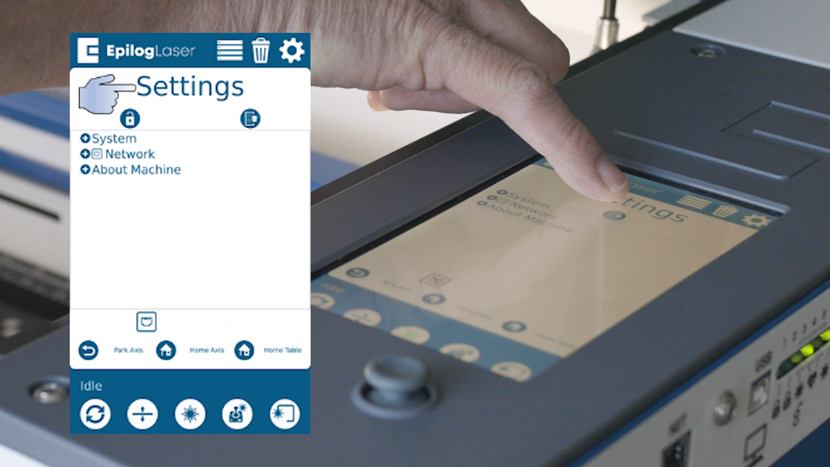
On the settings menu, long press the word “Settings” at the top of the screen.
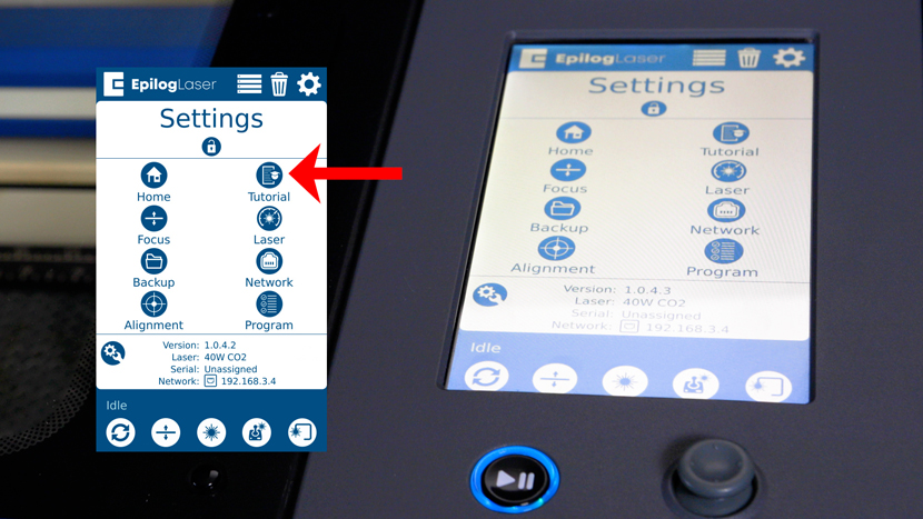
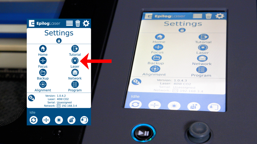
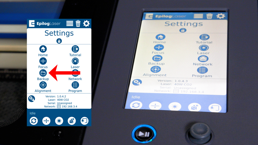
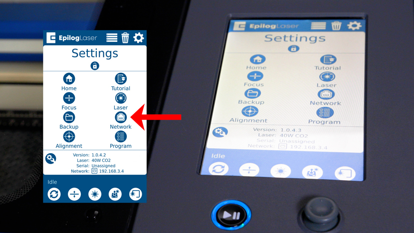
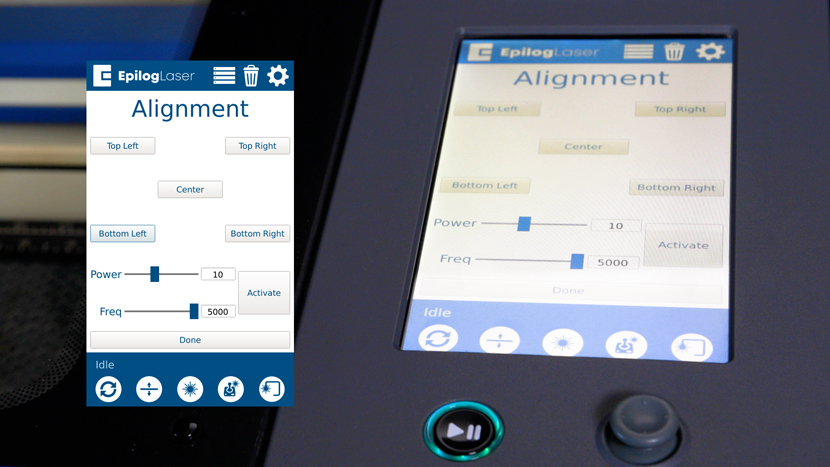
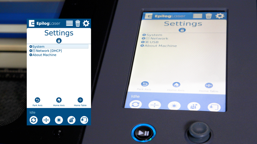
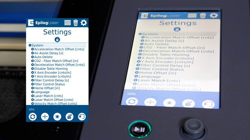
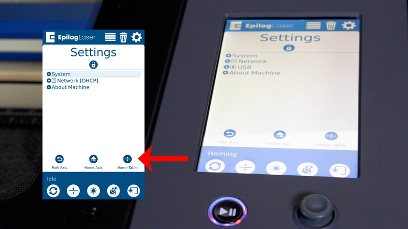
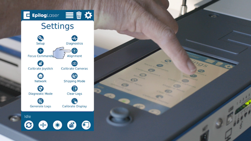
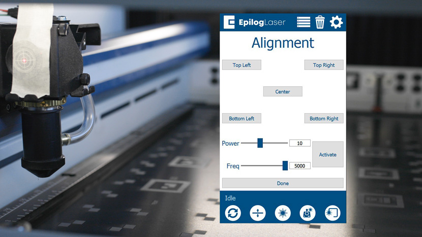
Next press “Alignment” to access the alignment menu.
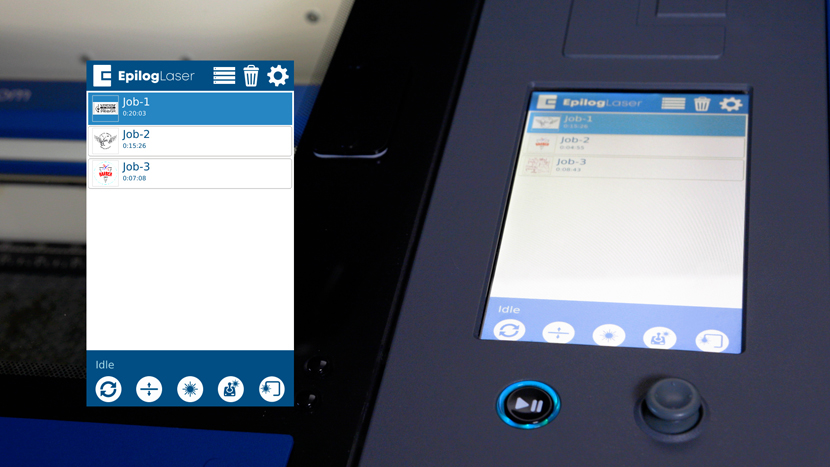
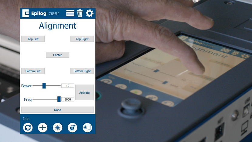
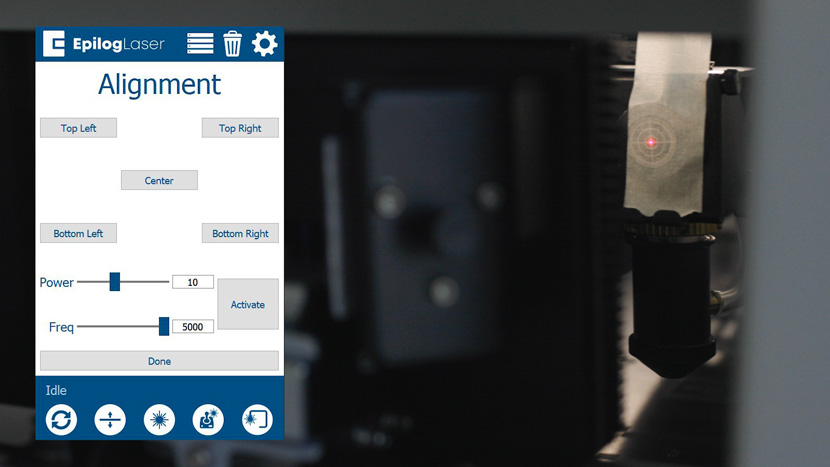
The Alignment Menu has 5 buttons that will move the carriage to their corresponding locations when pressed. It also has a button labeled “Activate” that will allow you to fire the laser for the purpose of alignment. We will use these commands to align the laser in each corner of the engraver to ensure that there is even power throughout the table. Note: In Alignment Mode, all interlocked access doors must be closed for the laser to fire.
Aligning the Laser and the Red Dot Pointer
Note: If you are performing the alignment because you have replaced Mirror 3 or the X-axis rail, please move to Part 2. For all other alignments, this procedure must be completed.
It is crucial that you align the red dot pointer and CO2 laser before adjusting the mirrors for each corner. If the Red dot pointer and the CO2 laser are not aligned to each other before starting Procedure 2, the alignment procedure will fail.
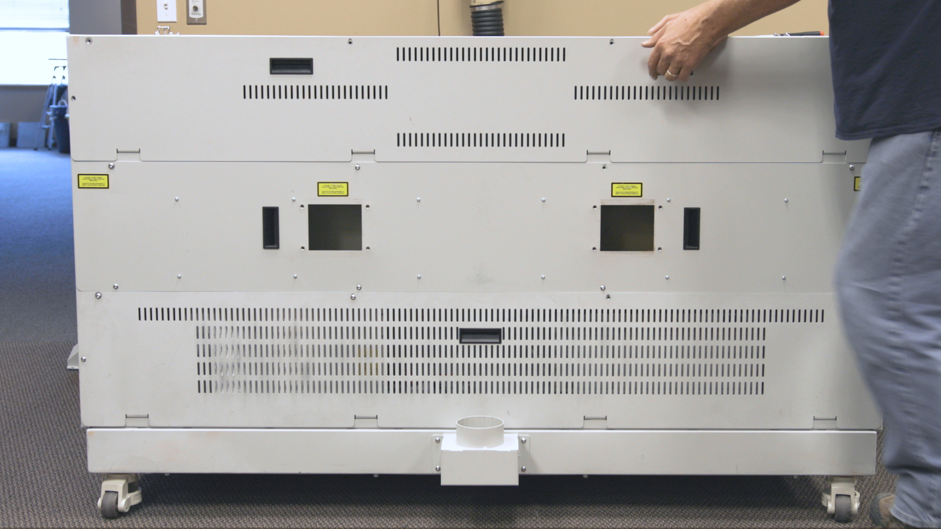
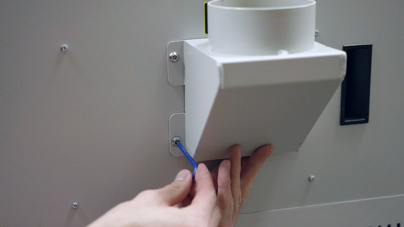
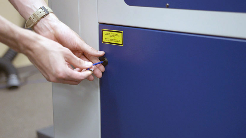
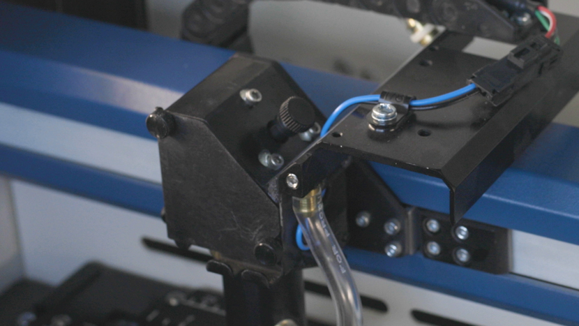
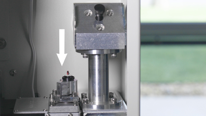
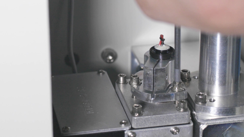
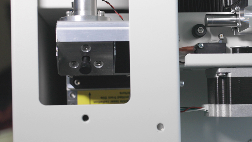
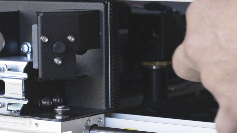
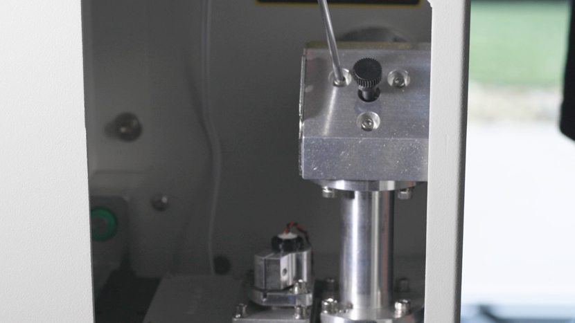
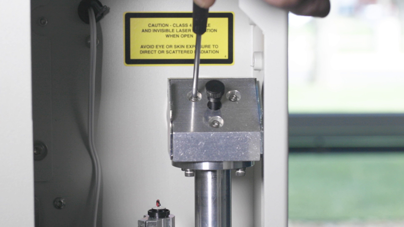
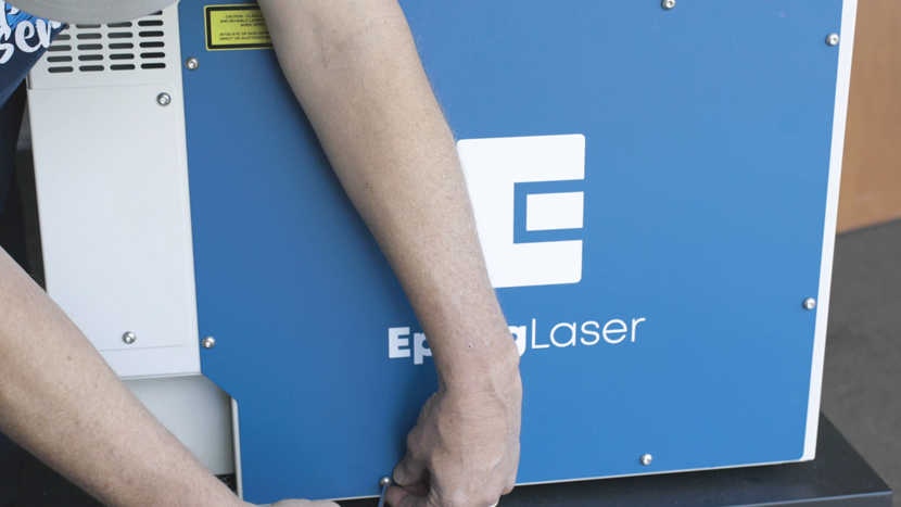
Move to the rear of the machine and look to the right-hand side as you are facing the machine from the rear and locate the Red Dot pointer assembly.
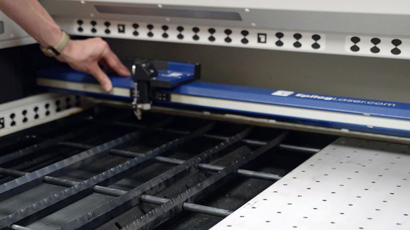
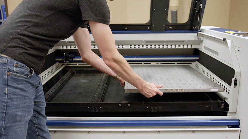
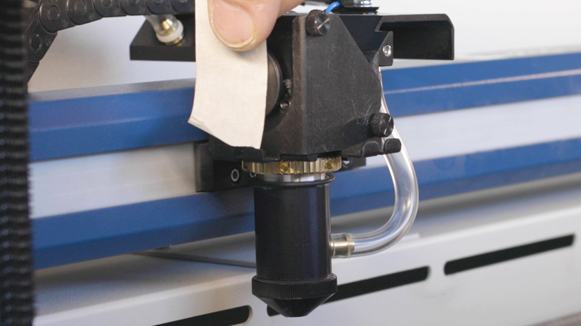
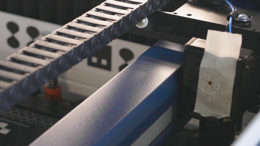
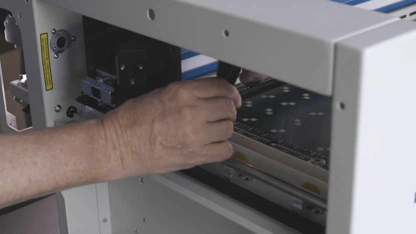
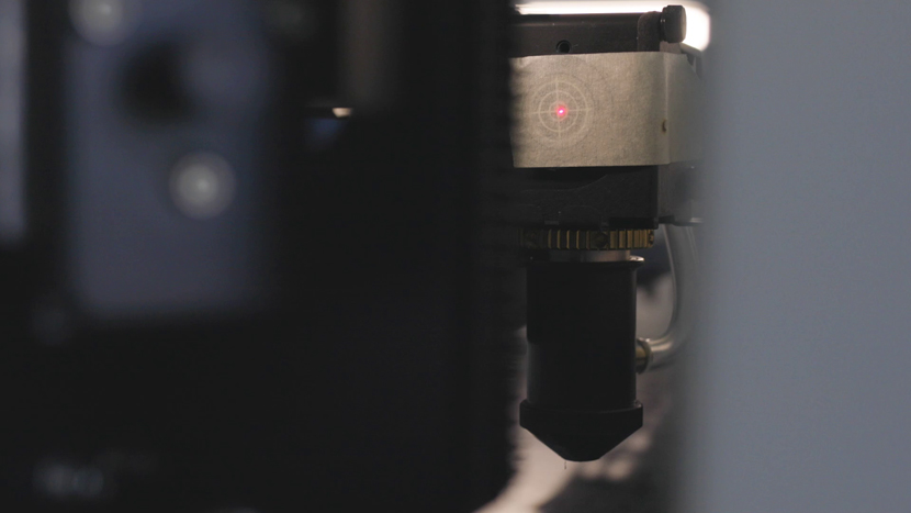
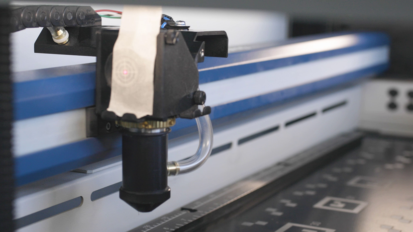
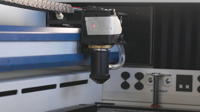
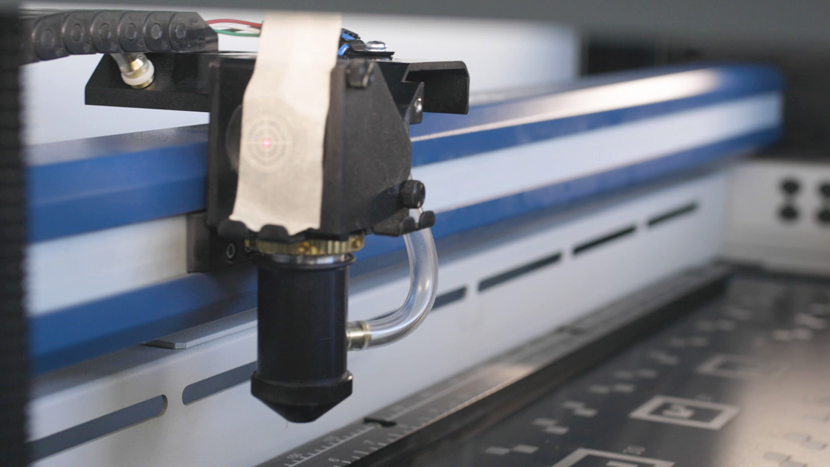
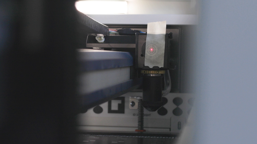
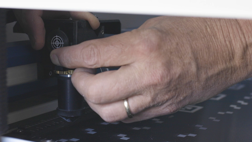
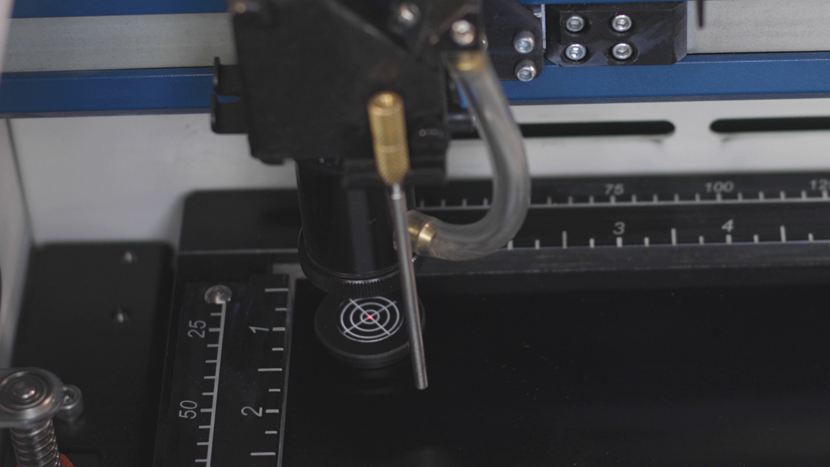
Locate the alignment target and place it into the left side of the lens carriage. It should fit into the lens carriage optic.
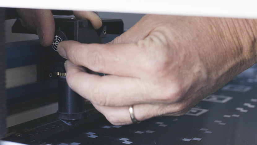
Place a square of masking tape over the alignment target. This will allow us to see the burn made by the CO2 laser.
With the target covered, press the “Bottom Right” button of the alignment menu to move the carriage to Position 4.
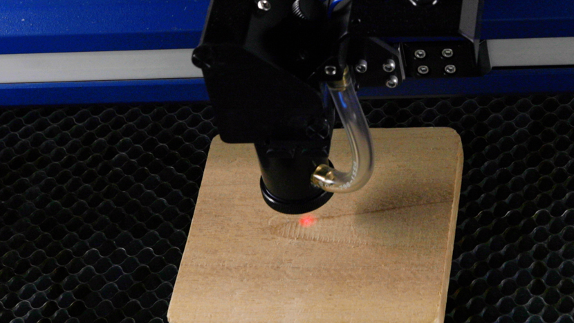
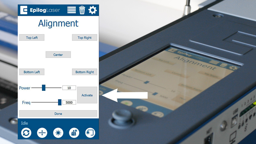
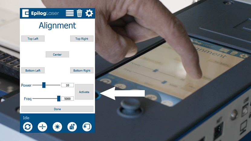
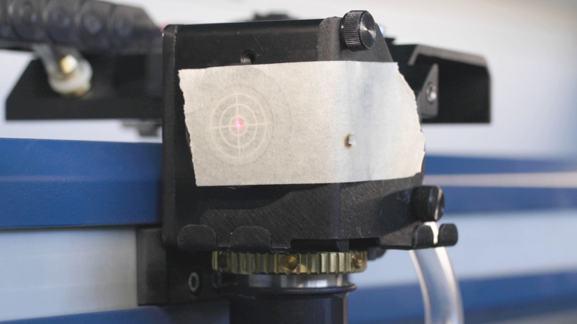
Press the “Activate” button to fire the laser. When Pressing the “Activate” button to fire the laser, use short brief taps of the button. The smaller and lighter you can make the burn mark on the tape, the easier it will be to get the pointer well centered in the burn mark. Please note, that the top door must be closed for the laser to fire when pressing the “Activate” button.
If you are unable to produce a burn mark on the tape, try setting the power to 15-20% and ensure that the lid is closed.
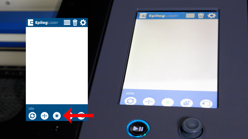
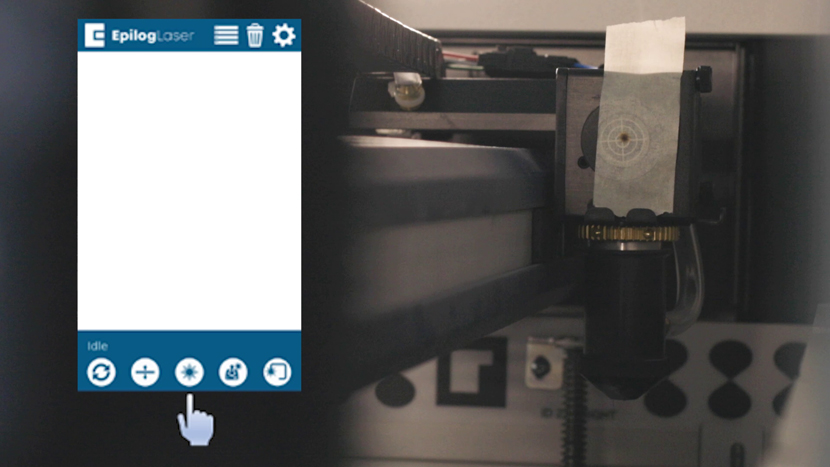
Now that there is a burn mark on the masking tape, press the Red Dot Pointer icon on the engraver’s display to activate the Red Dot Pointer.
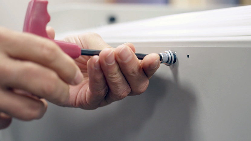
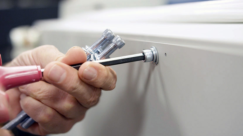
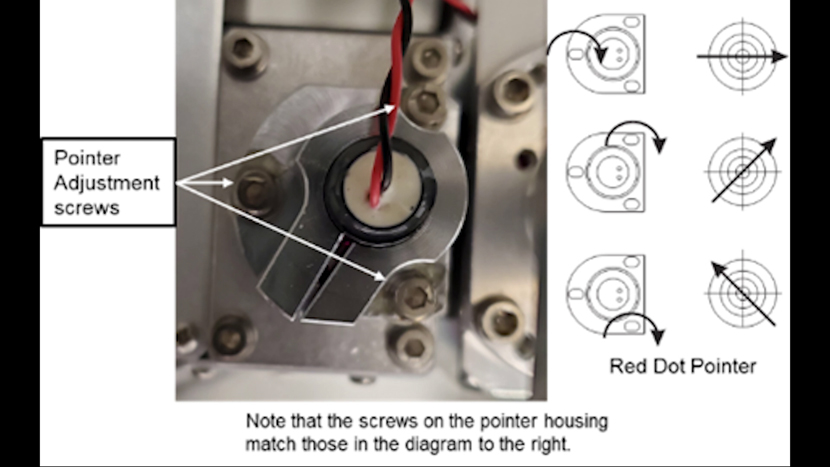
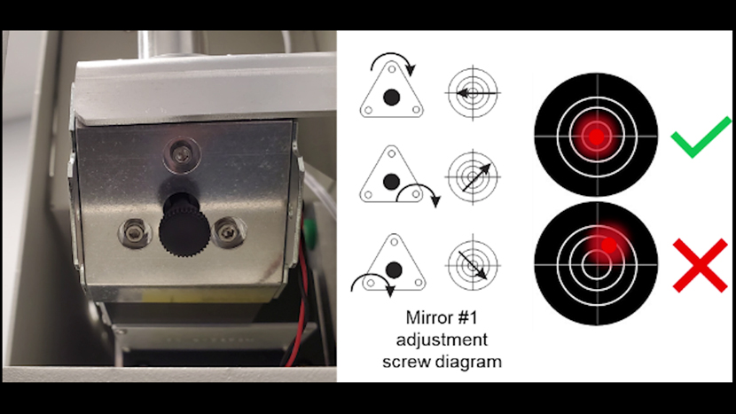
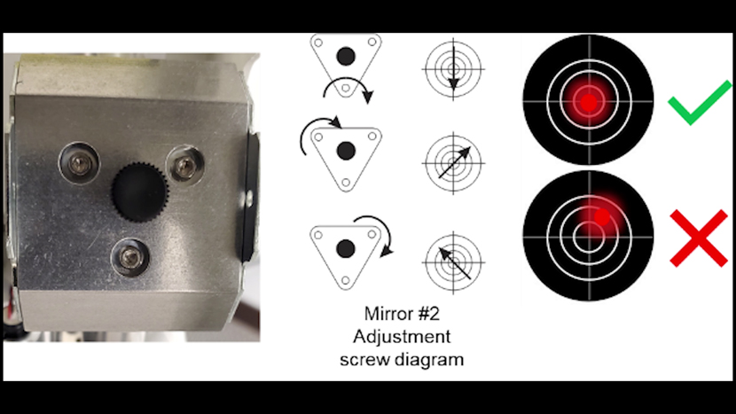
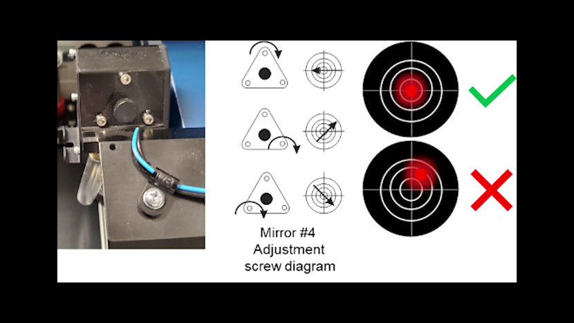
At the rear of the machine, use the three adjustment screws on the Red Dot Pointer Mount, to move the Red Dot Pointer to the burn mark on the tape. The Red dot pointer will move across the alignment target according to the following diagram.
Take your time with this part of the process. Ensuring that the Laser and the Red Dot are well aligned will make the remainder of this procedure more effective.

Aligning the laser in each corner
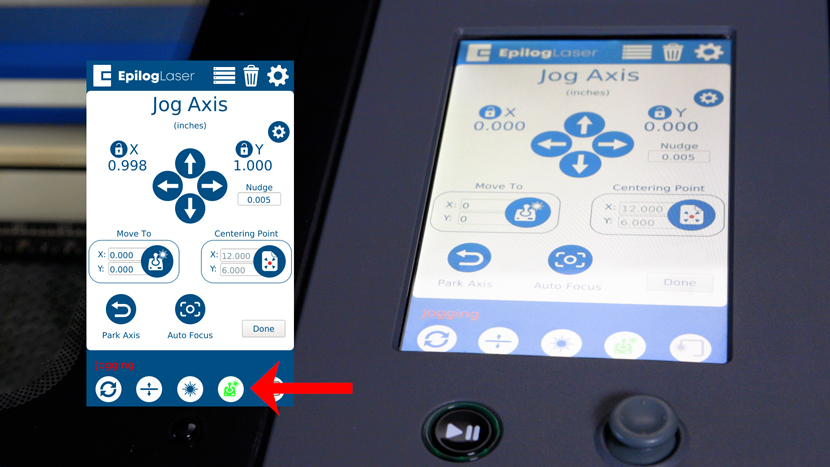
Keeping your safety glasses on, turn on the Red Dot pointer at the touchscreen display if it is not already on.
At the touchscreen, navigate to the Alignment menu in Settings and tap “Top Left”, image 29, to move the carriage to position 1.
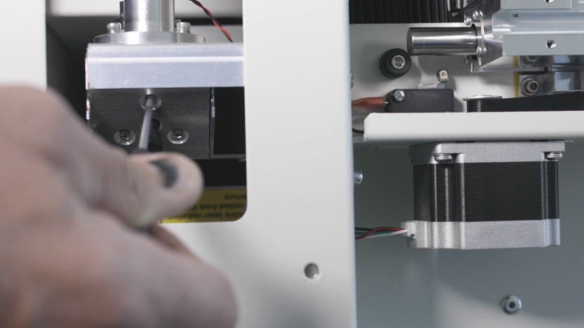
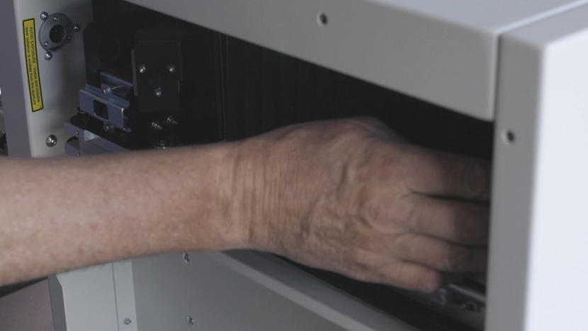
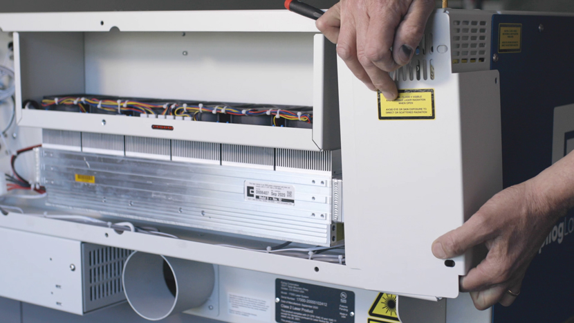
Locate Mirror #1 under the bottom mirror access panel.
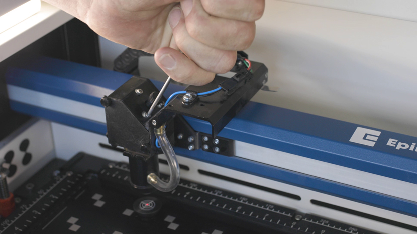
Using a 3/32” hex key and the following guide image, adjust the screws on Mirror #1 so that the Red Dot Pointer is in the center of the alignment target while the carriage is in Position 1.
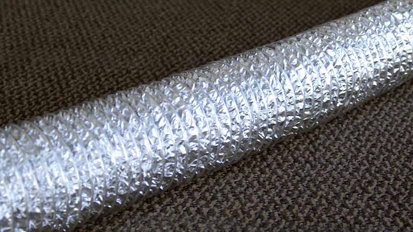
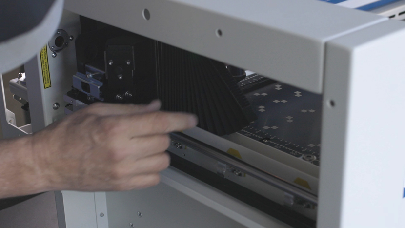
If you are having difficulty seeing the red dot pointer as it is very close to the upper right-hand corner, you can free the bellows from the X-axis assembly by gently pulling on the top of the bellows where it connects to the X-axis assembly.
Once red dot pointer has been centered in the first corner, tap “Bottom Left” on the touchscreen to move the carriage to Position 2.
Locate Mirror #2 behind the mirror access panel.
Using the 3/32” Allen wrench and the guide, adjust the screws on Mirror #2 so that the Red Dot Pointer is in the center of the alignment target in Position 2.
Once complete, return to Position 1 (upper-left) and re-adjust Mirror 1 until it is aligned again in Position 1. Once you are done, move back to Position 2 and adjust Mirror 2.
Note: You may have to go back and forth between positions 1 and 2 multiple times before the Red Dot is centered in both corners. Each time you re-adjust the mirrors, the Red Dot should move closer and closer to the center of the target and will drift apart less when moving back and forth between positions 1 and 2.
Once Positions 1 and 2 have both been centered and no longer drift apart, you can adjust mirror #3. Using the touch screen display, tap “Top Right” to move the carriage to Position 3.
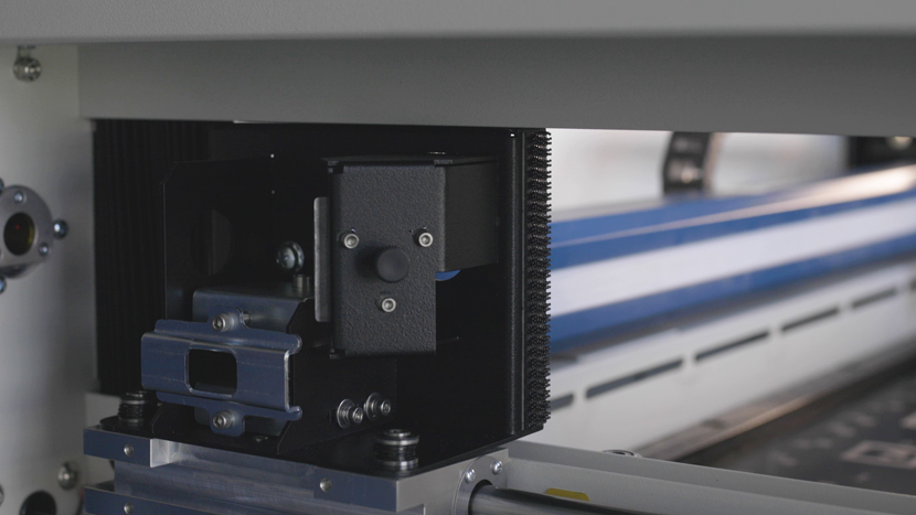
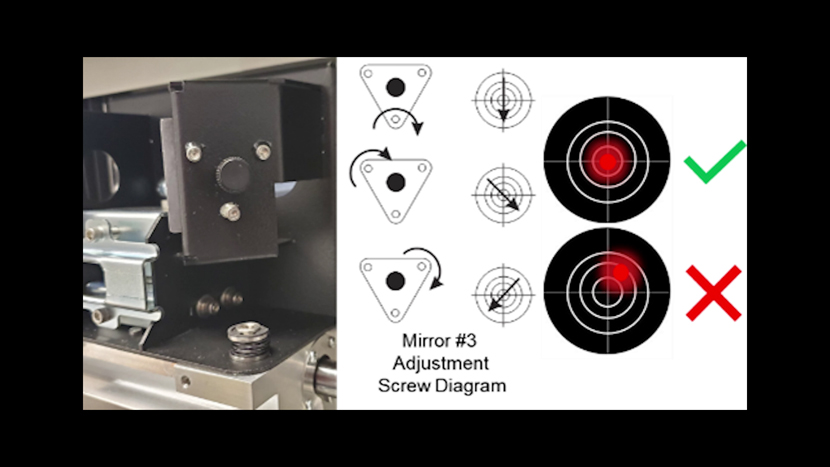
Mirror #3 is located on the far left-hand side of the X axis rail.
Using the 3/32” Allen wrench and the guide in the image below, adjust the screws on Mirror #3 so that the Red Dot Pointer is in the center of the alignment target.
Once complete, return to Top Left & Mirror 1, and then Bottom Left & Mirror 2. Continue to align Mirrors #1, #2 and #3 until you can move between the 3 positions without the Red Dot leaving the Center of the Alignment Target.
Once you are confident that you are aligned between Positions #1, #2 and #3, press the button to job the lens carriage to Bottom Right/Position #4.
If all the mirrors are aligned correctly, the red dot pointer should appear within the center ring on the alignment target. If so, you may remove the alignment target, replace the panels that were removed earlier and run a test engraving file. If not, please return to the Upper Left/Position #1 and continue alignment.
Perpendicular Alignment
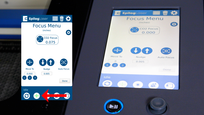
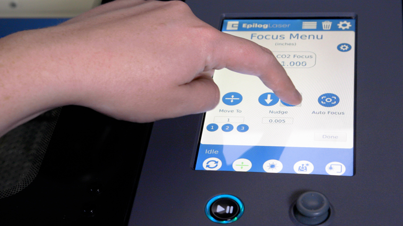
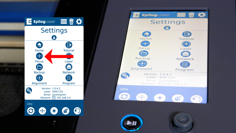
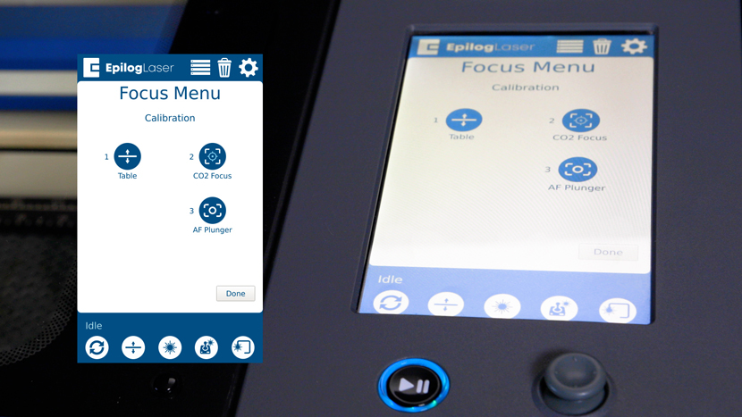
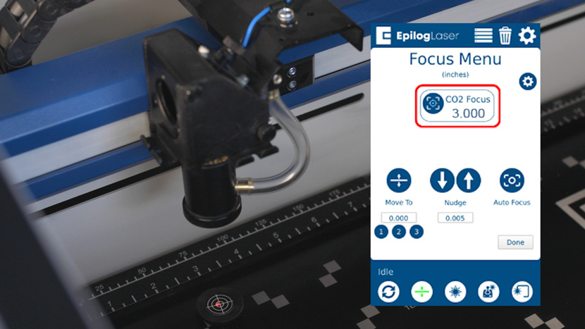
Press the Focus Menu button on the touch screen.
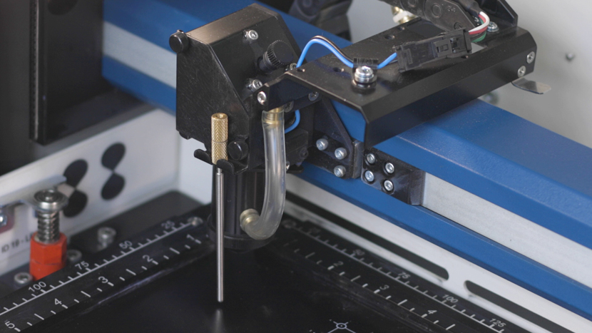
Place the Manual Focus Gauge on the laser assembly. Use the joystick to move the table until the Manual Focus Gauge touches the table. You will want to bring the table up until the Focus Gauge is just touching the top of the table surface.
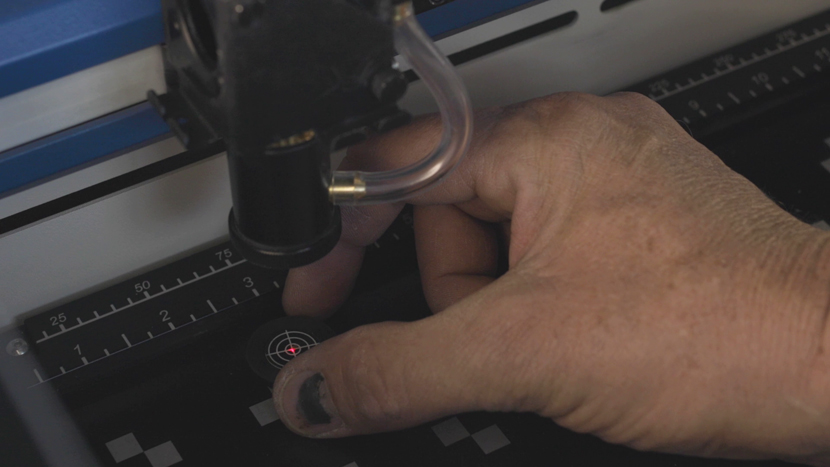
Place the alignment target on the table so that the Red dot pointer is in the center of the bullseye.
Using the joystick on the engraver’s display, lower the bed until “Current Focus” reads roughly “3.000”
Check the location of the Red Dot Pointer and see if it has moved off center of the alignment target.
Using the 3/32 Hex Key and the guide image, adjustment screws on the Carriage Mirror to move the Red Dot Pointer back onto the center of the target.
Using the Joystick, bring the table back up until the focus gauge is touching the bed again.
If the red dot has moved, repeat this process until you can rise and lower the table without the Red Dot moving on the Alignment Target.
Alignment Verification
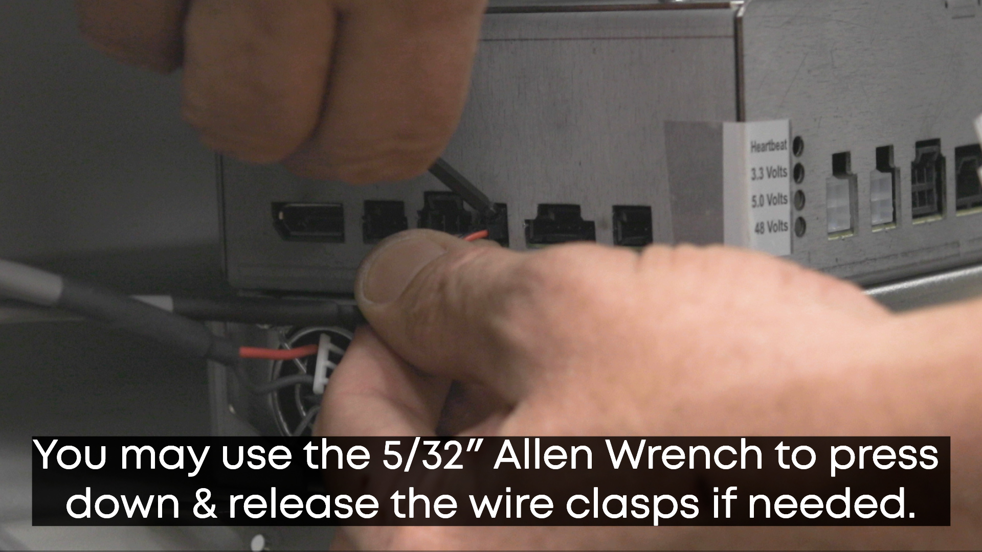
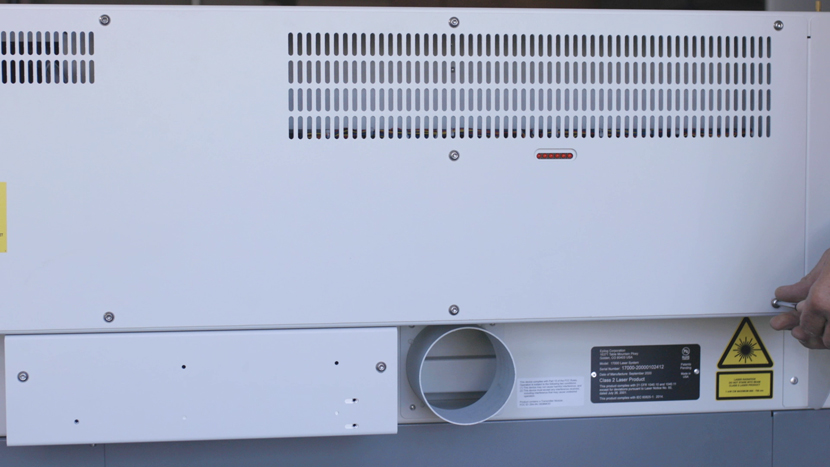
Once your laser is fully aligned, replace all the side panels and tighten the screws using a 5/32” hex key.
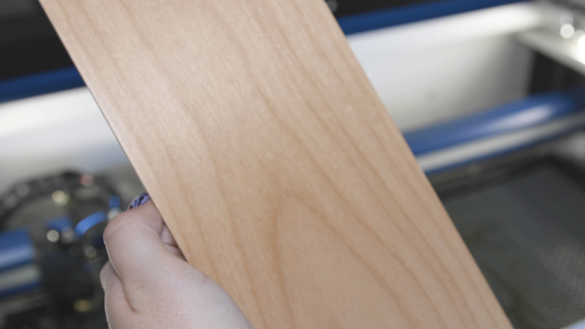
Obtain a piece of scrap material that is large enough to engrave 4 small boxes on. Preferably, this will be a piece of material you have used in the past and are familiar with the settings needed to produce quality engraving. This piece of material does not need to be the size of your table. We will move the piece from one corner to the next after each test engraving is complete.
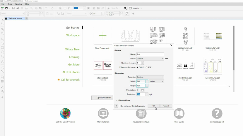
Create a new page that matches your engravers bed size in your art program of choice.
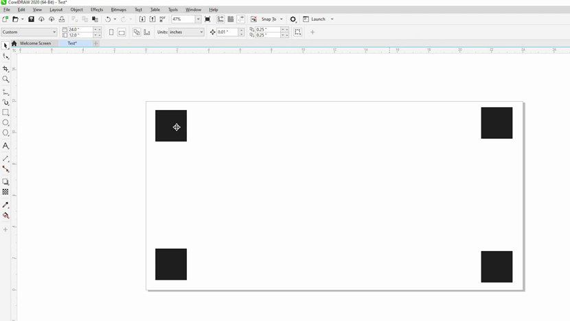
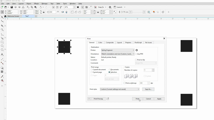
In your graphics software, create 4 small black filled boxes and place them in each of the 4 corners of the page.
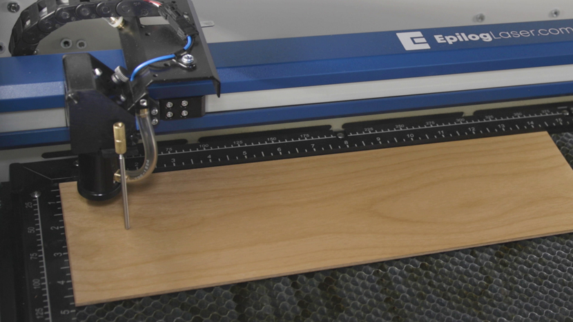
Place your test material in the upper left-hand corner of the engravers bed.
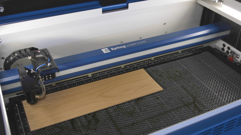
Manually focus your machine to eliminate focus as being a factor. Once the focus is set in the upper left-hand corner, do not change the table’s height.
Select the box in the upper left-hand corner and engrave it using the settings you have used previously.
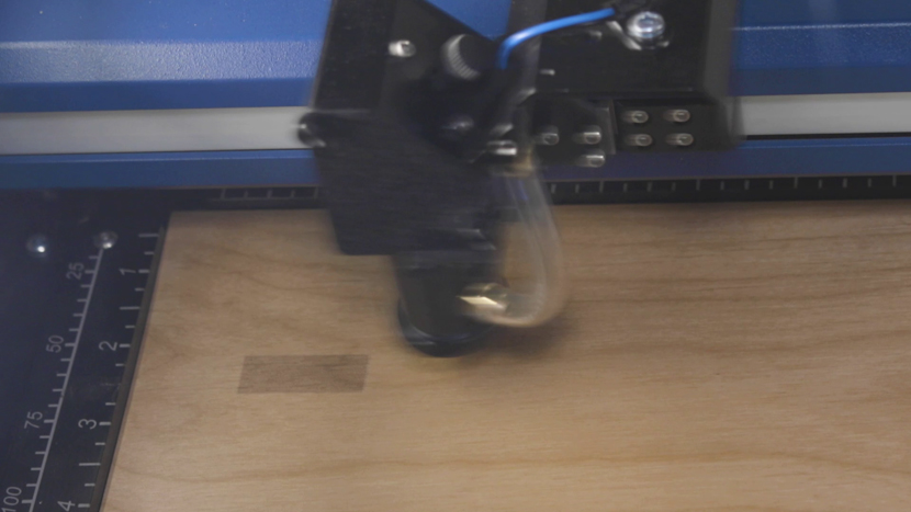
Select the box in the lower left-hand corner, move your material and run a test engraving there.
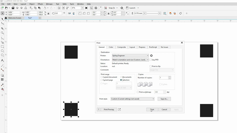
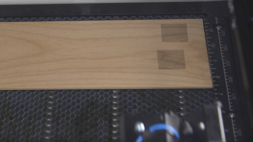
Repeat this process until all 4 boxes are engraved into your piece of scrap material.
Visually inspect each of the boxes for the following:
- Consistency of mark: There should be uniform discoloration of each of the boxes.
- Uniformity of depth. If engraved into wood or plastic, metal does not work for this test, each corner should be uniform in depth in each of the boxes you engraved.
Other indicators of a good alignment:
- Ability to use the same settings for your material in each corner of the table. There is no reason you should have to increase the power or decrease the speed to achieve similar results in each corner of your machine.