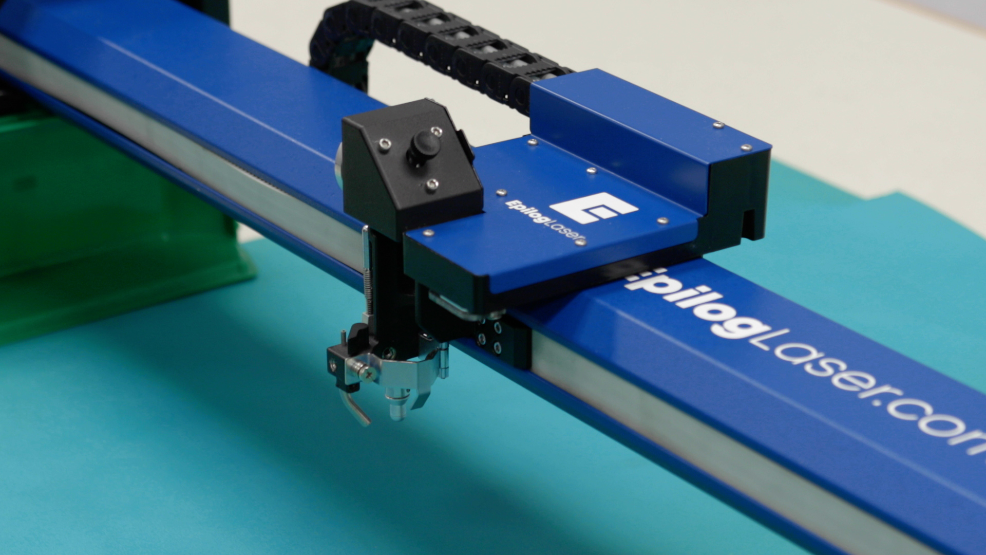
Replacing the Reducer Drive Assembly
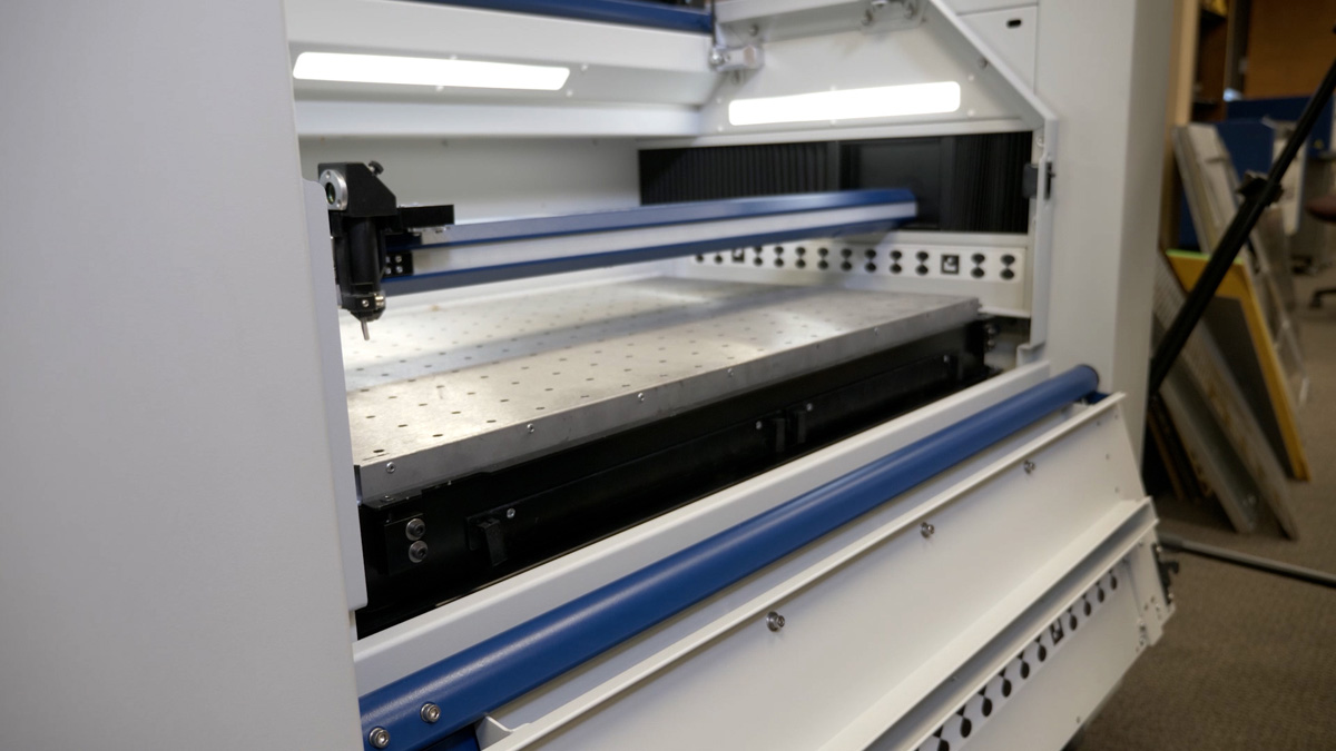
Remove Panels
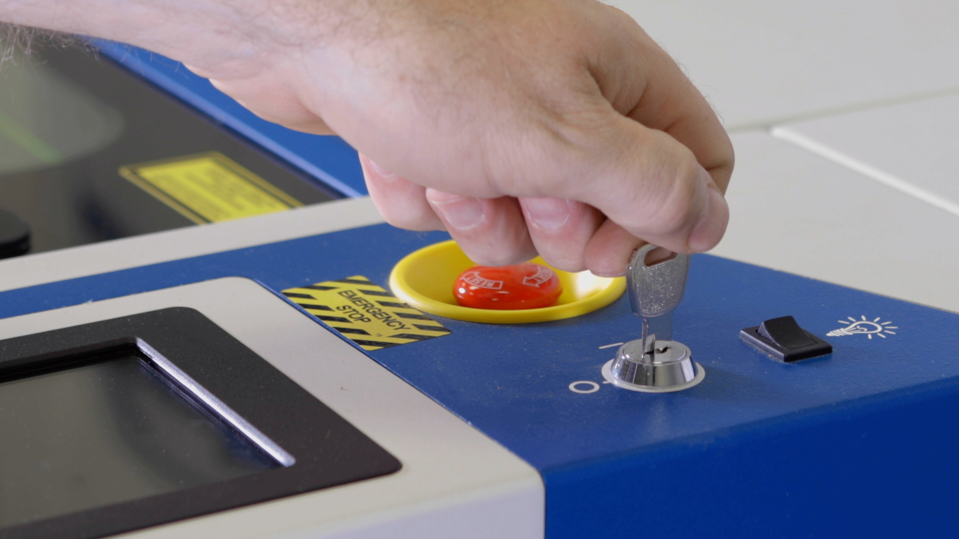
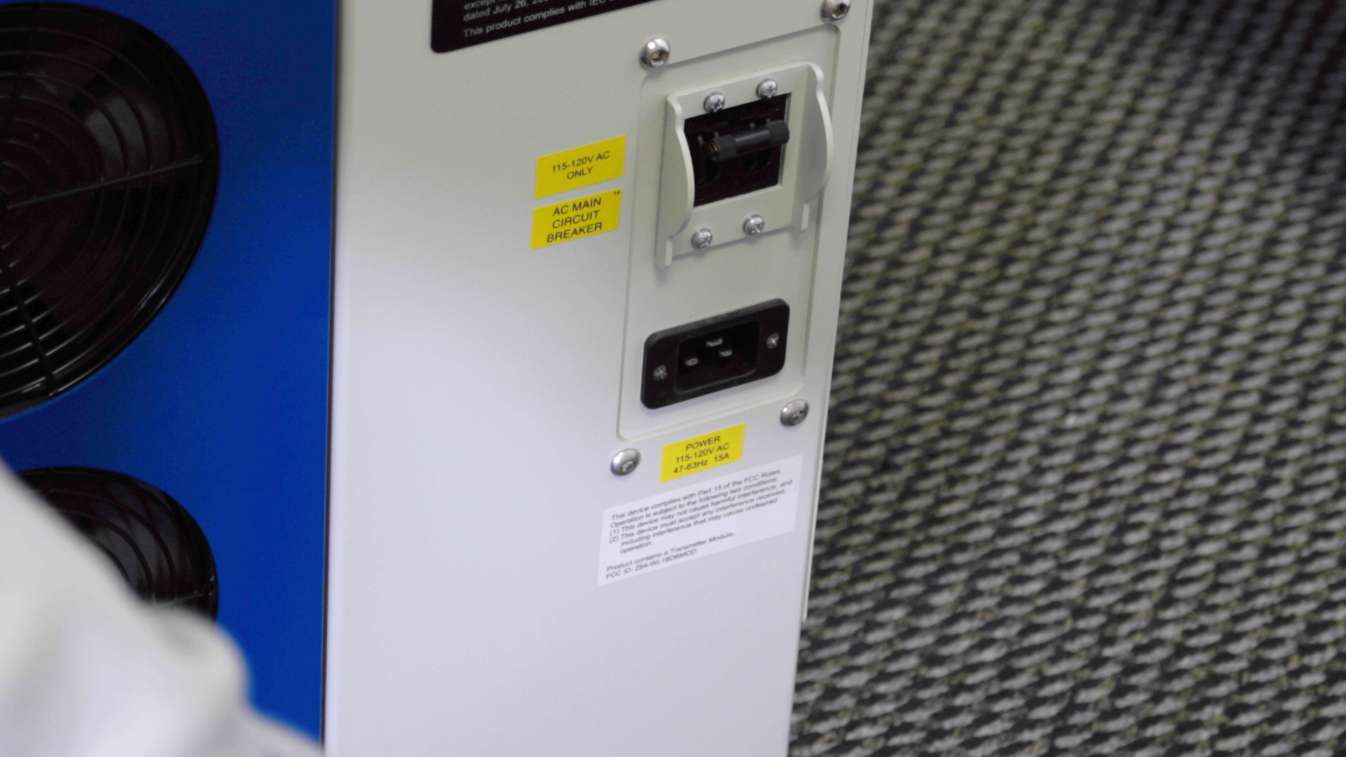
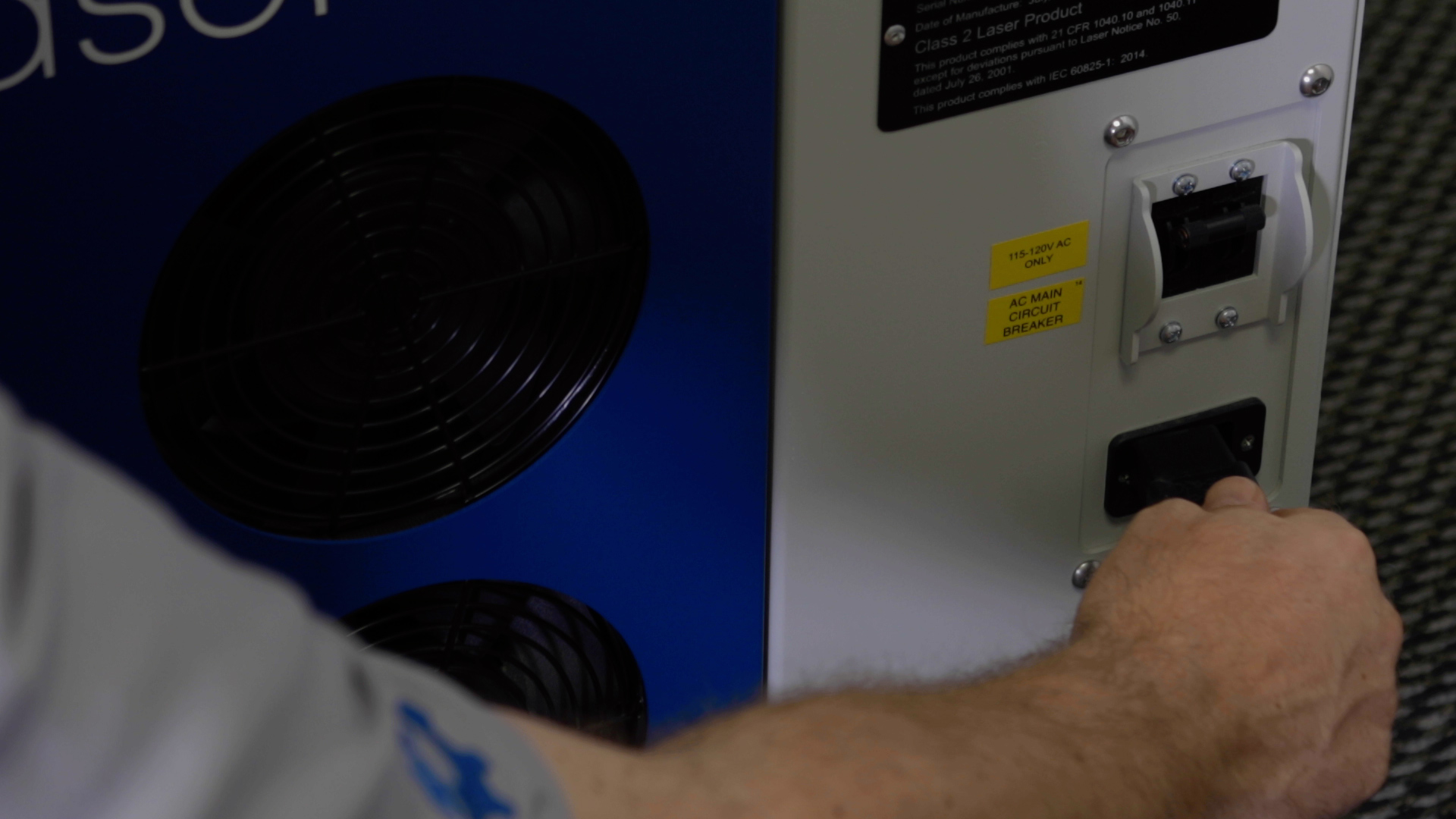
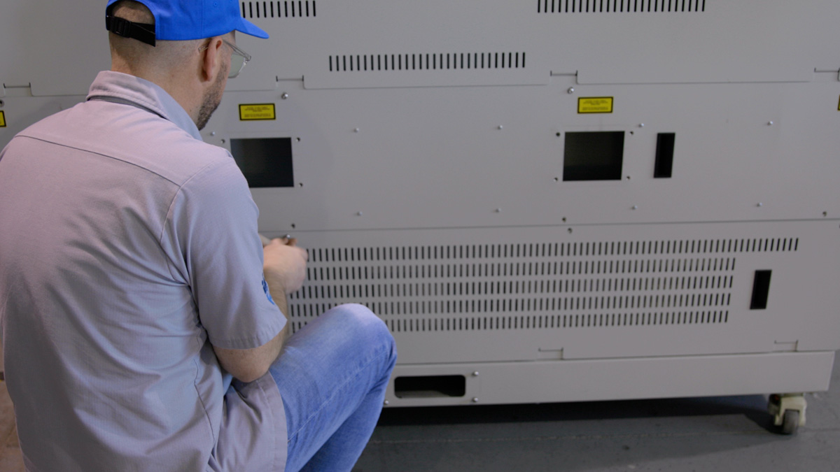
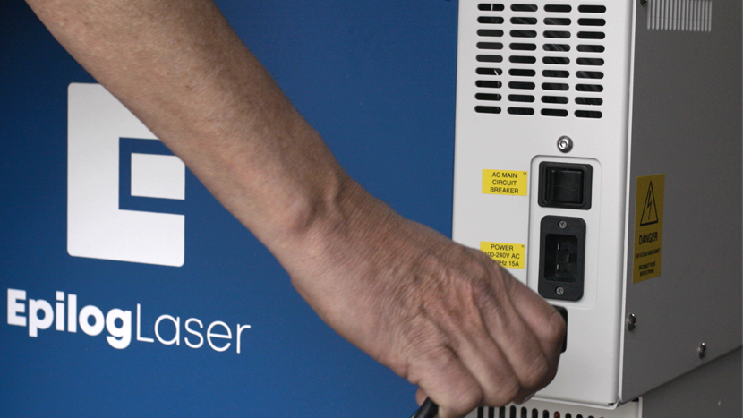
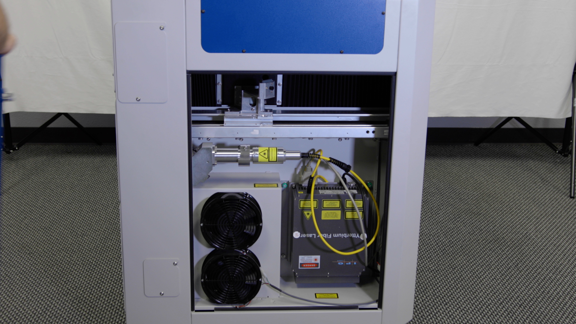
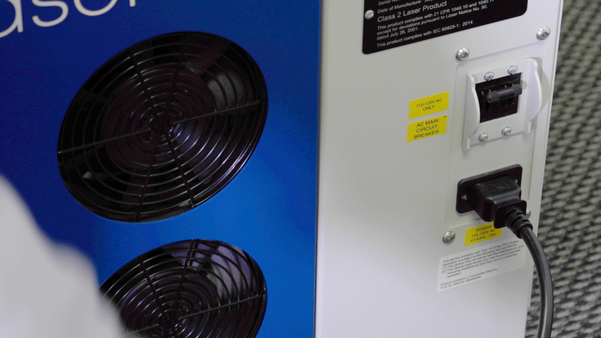
First, power off and unplug the machine.


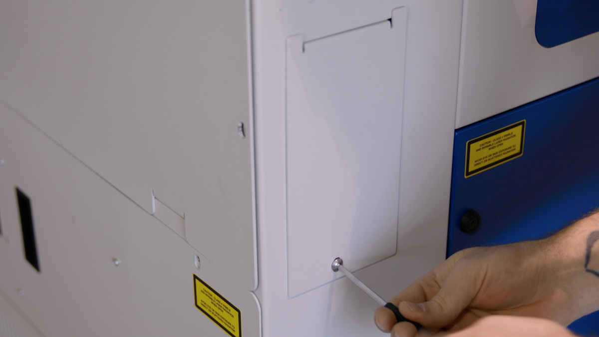
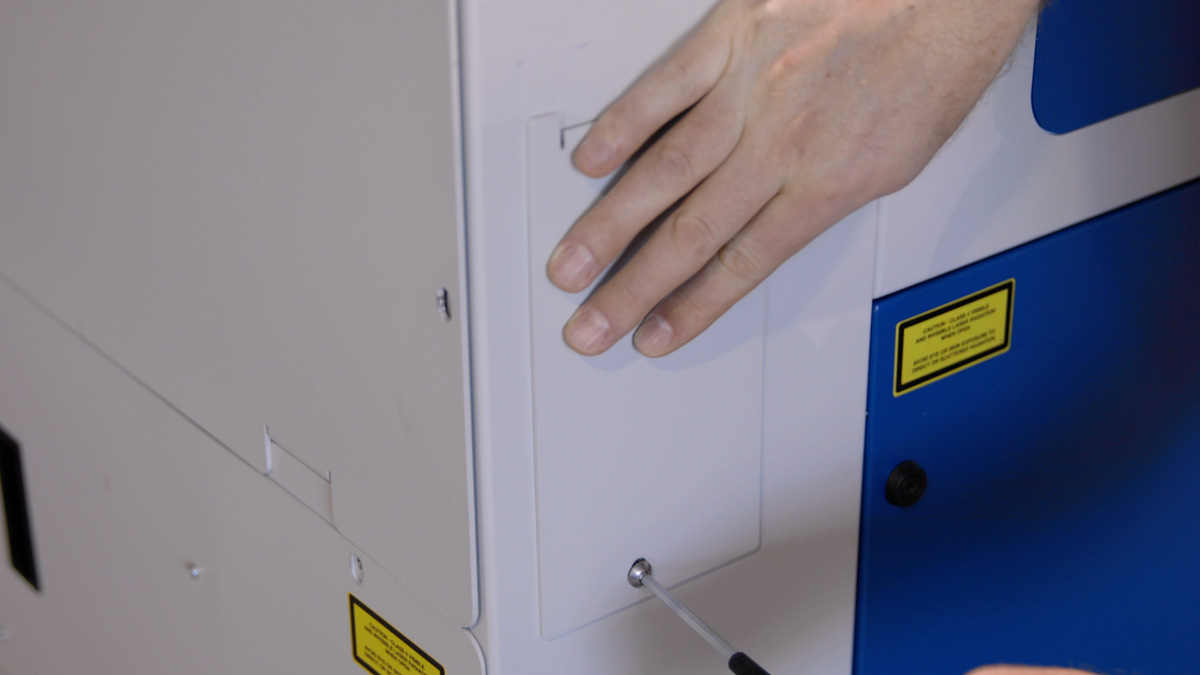
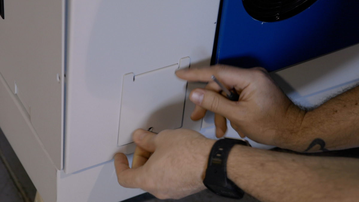
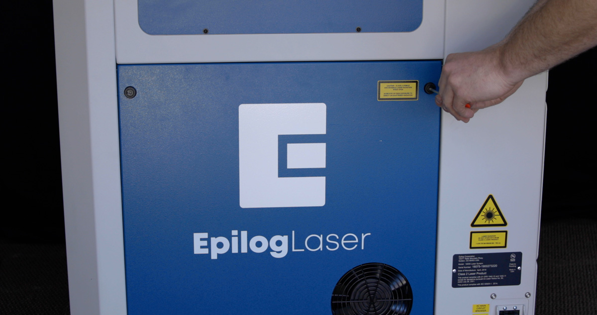
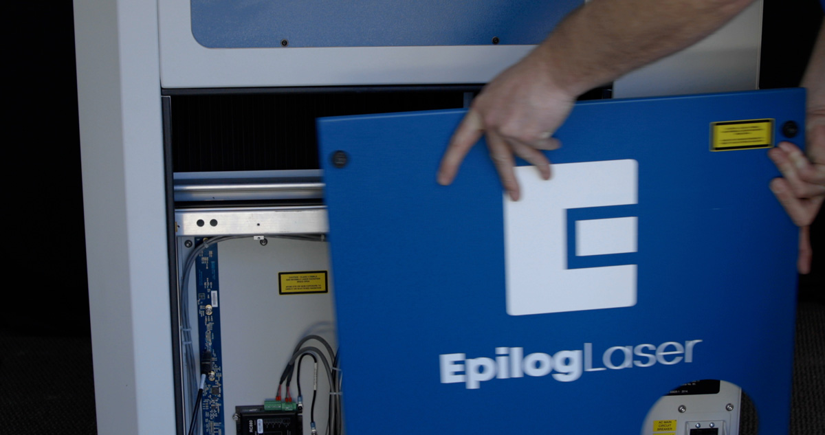
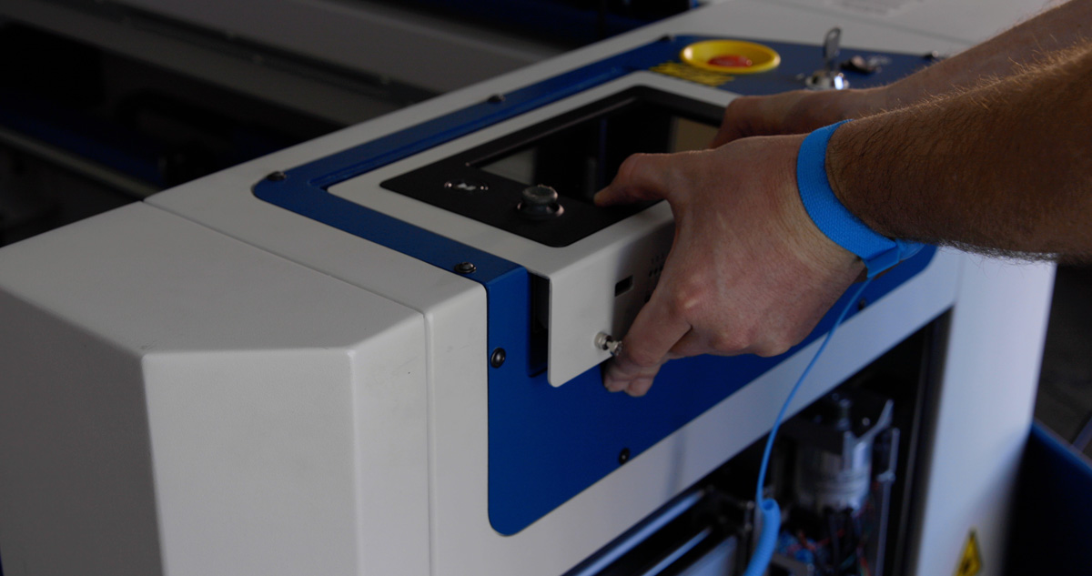
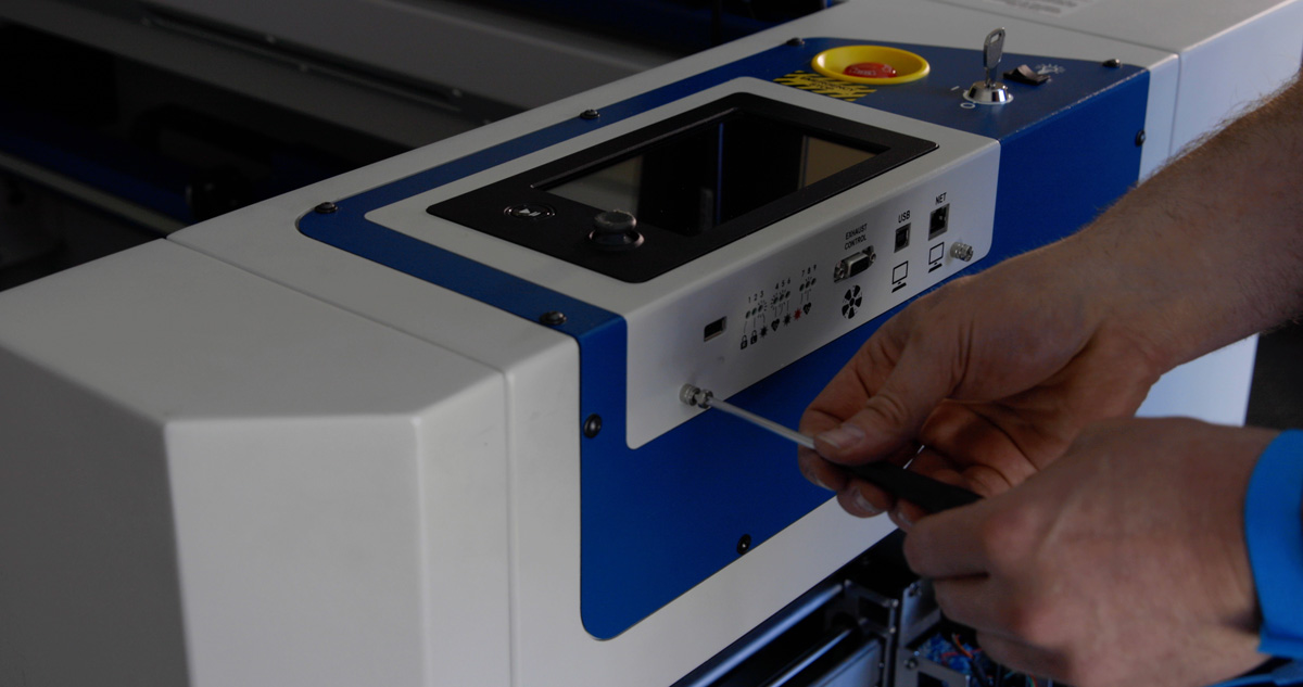
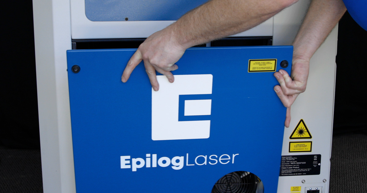
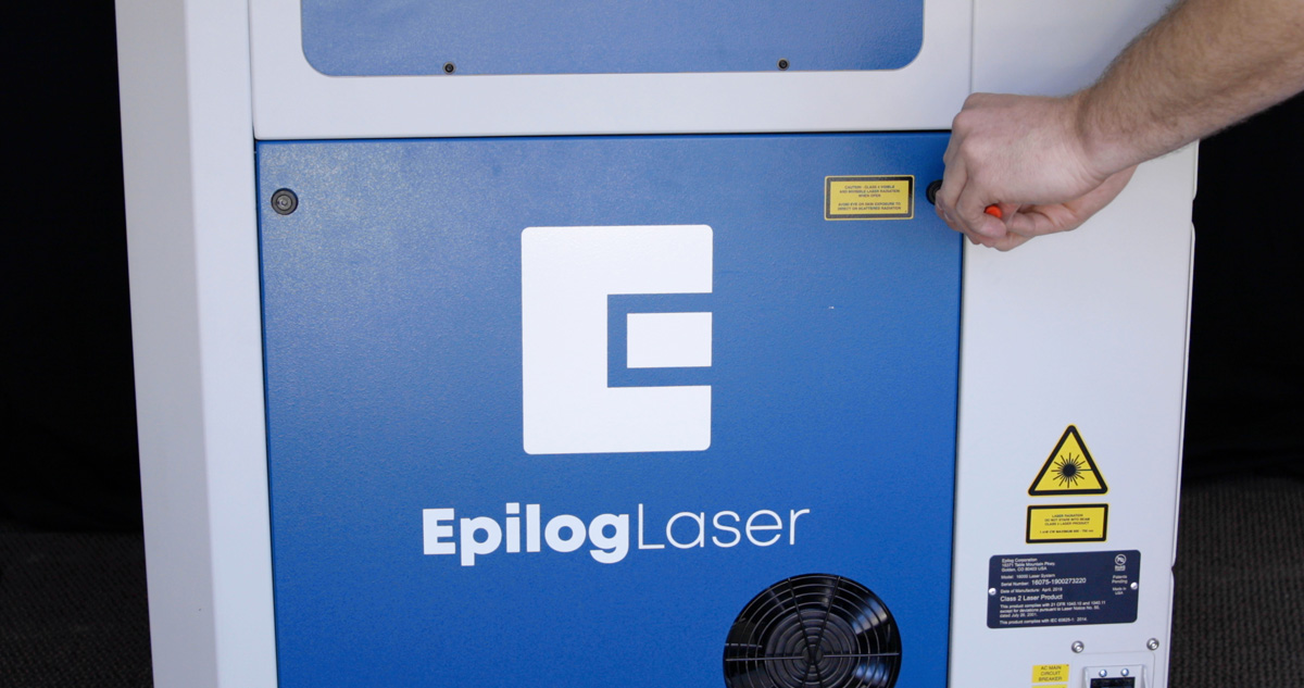
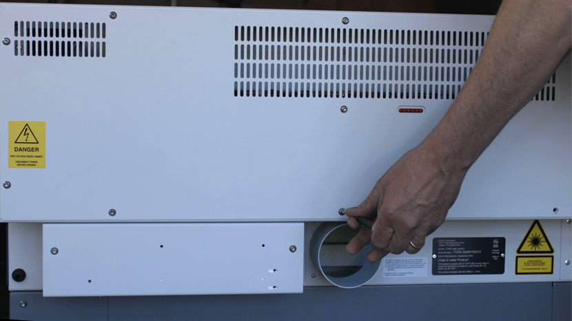
Using a 5/32” Allen Key, remove the right side panel from the machine.
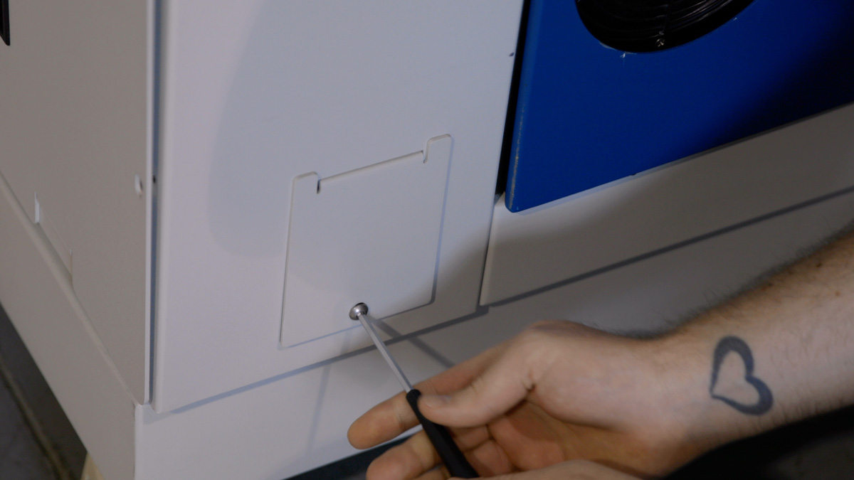
Using a 5/32” Allen Key, remove the left side panel from the machine.
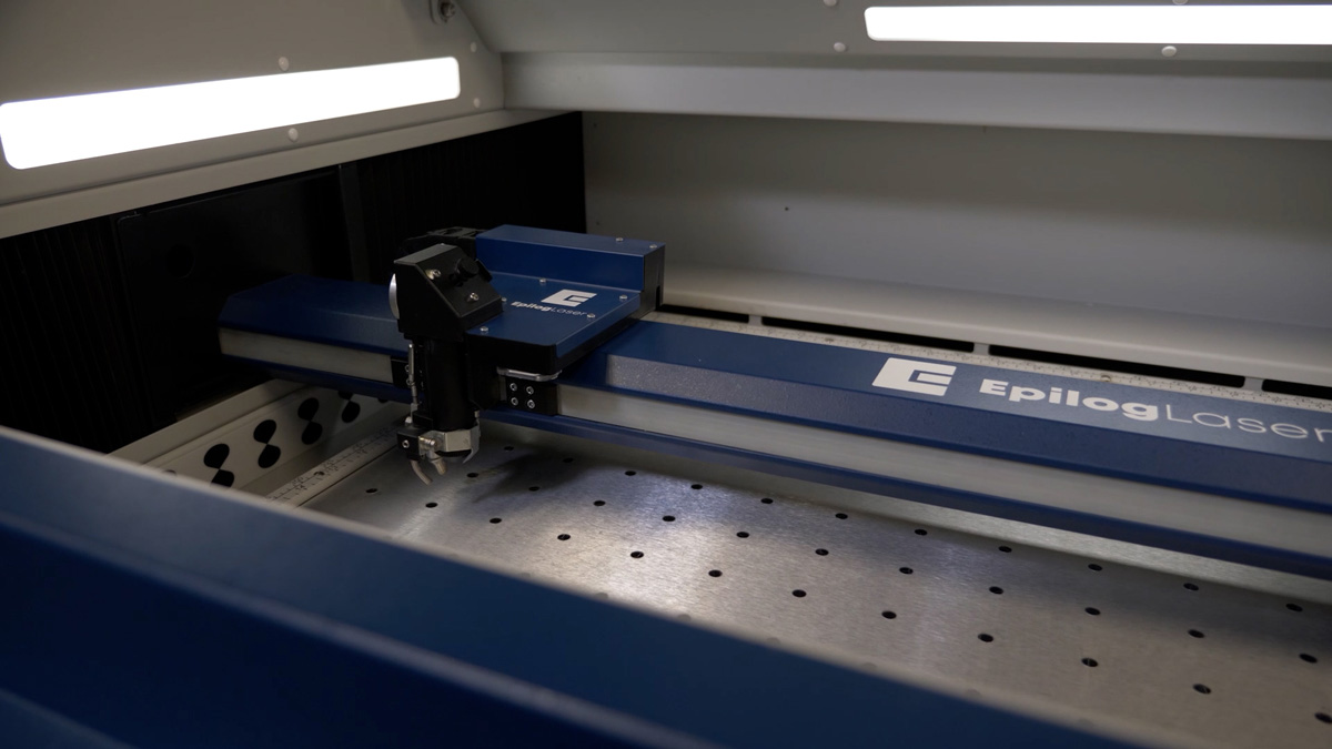
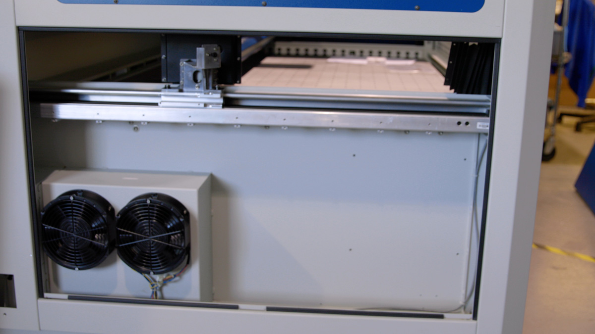
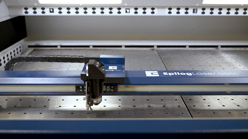
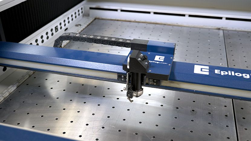
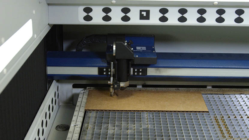
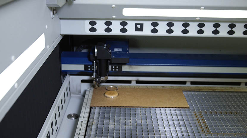
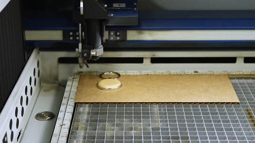
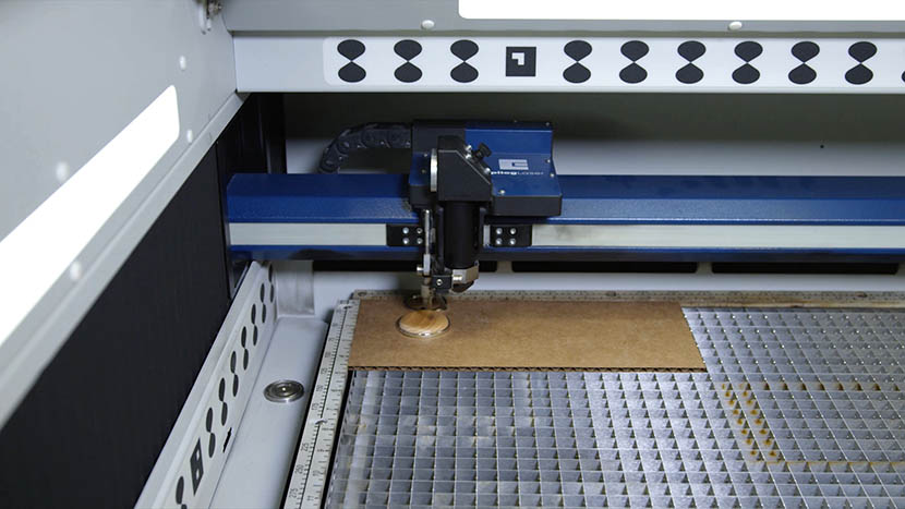
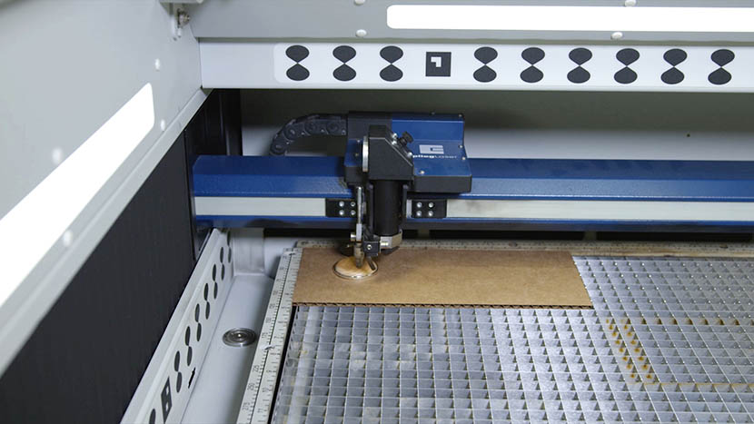
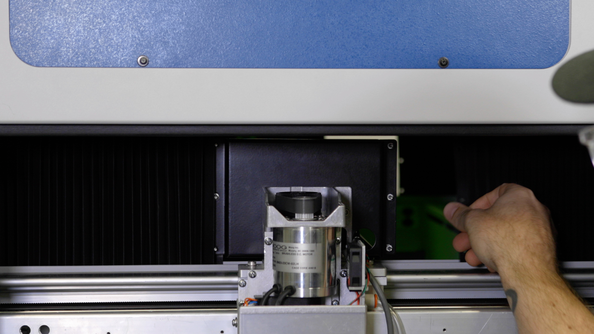
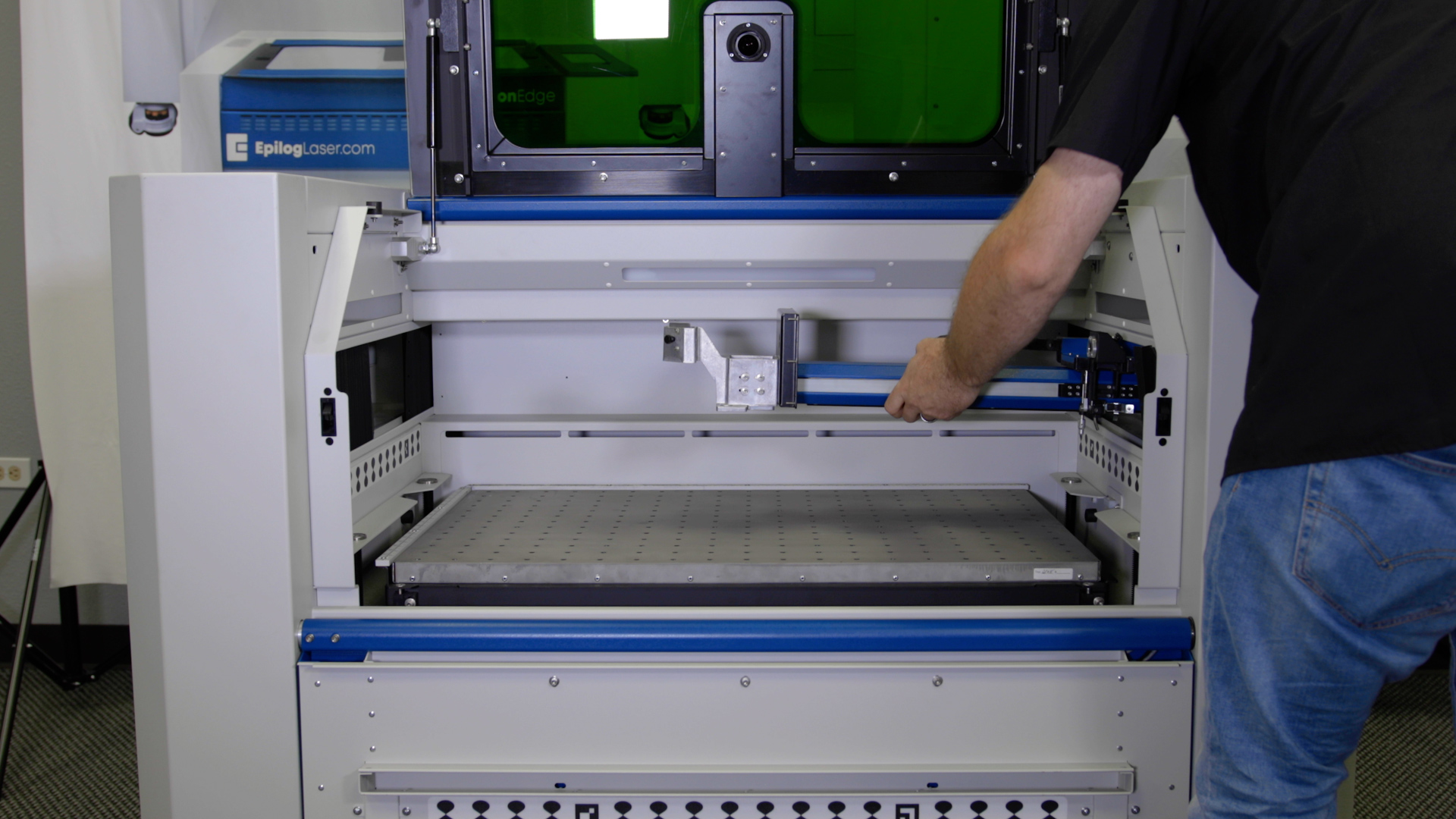
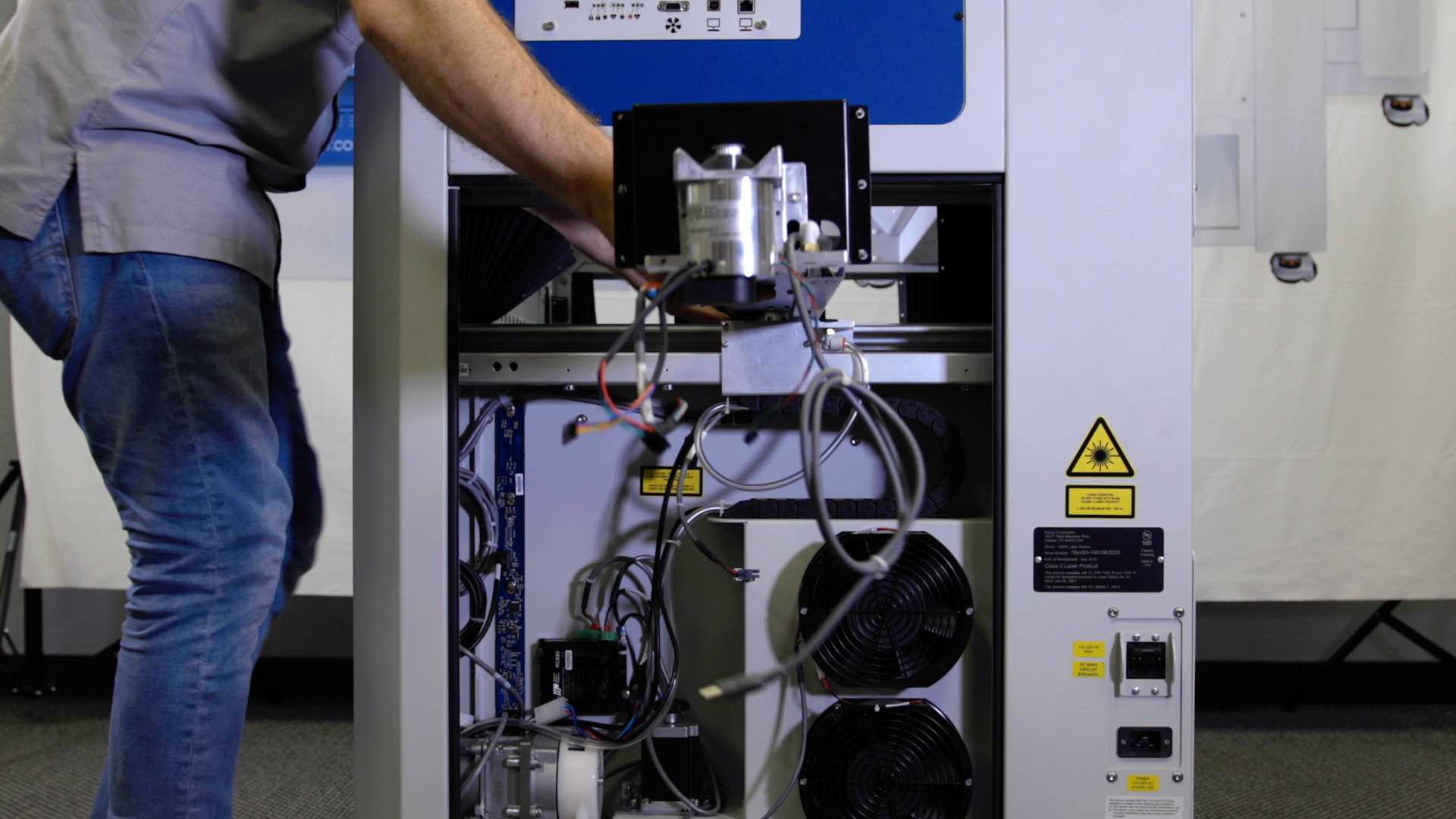
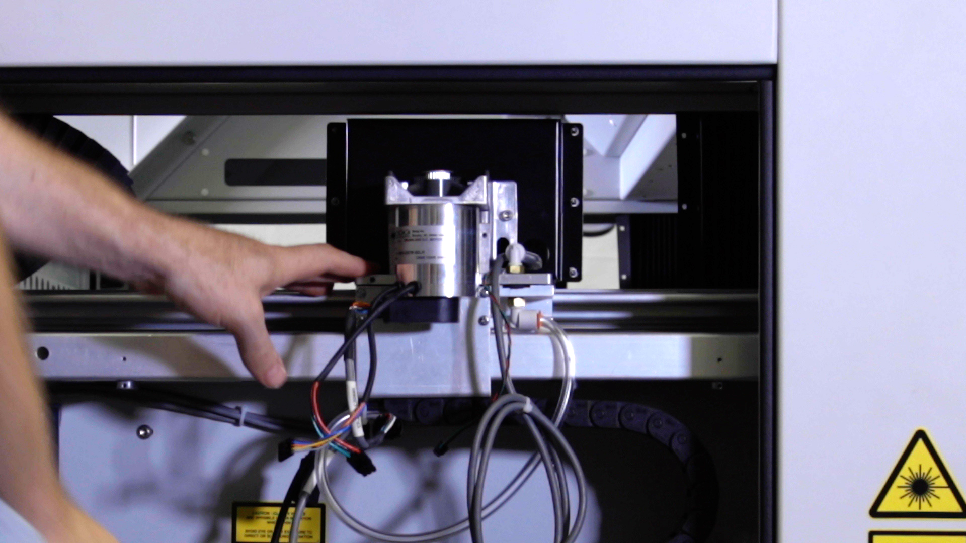
Manually move the x-axis assembly to the middle of the engraver.
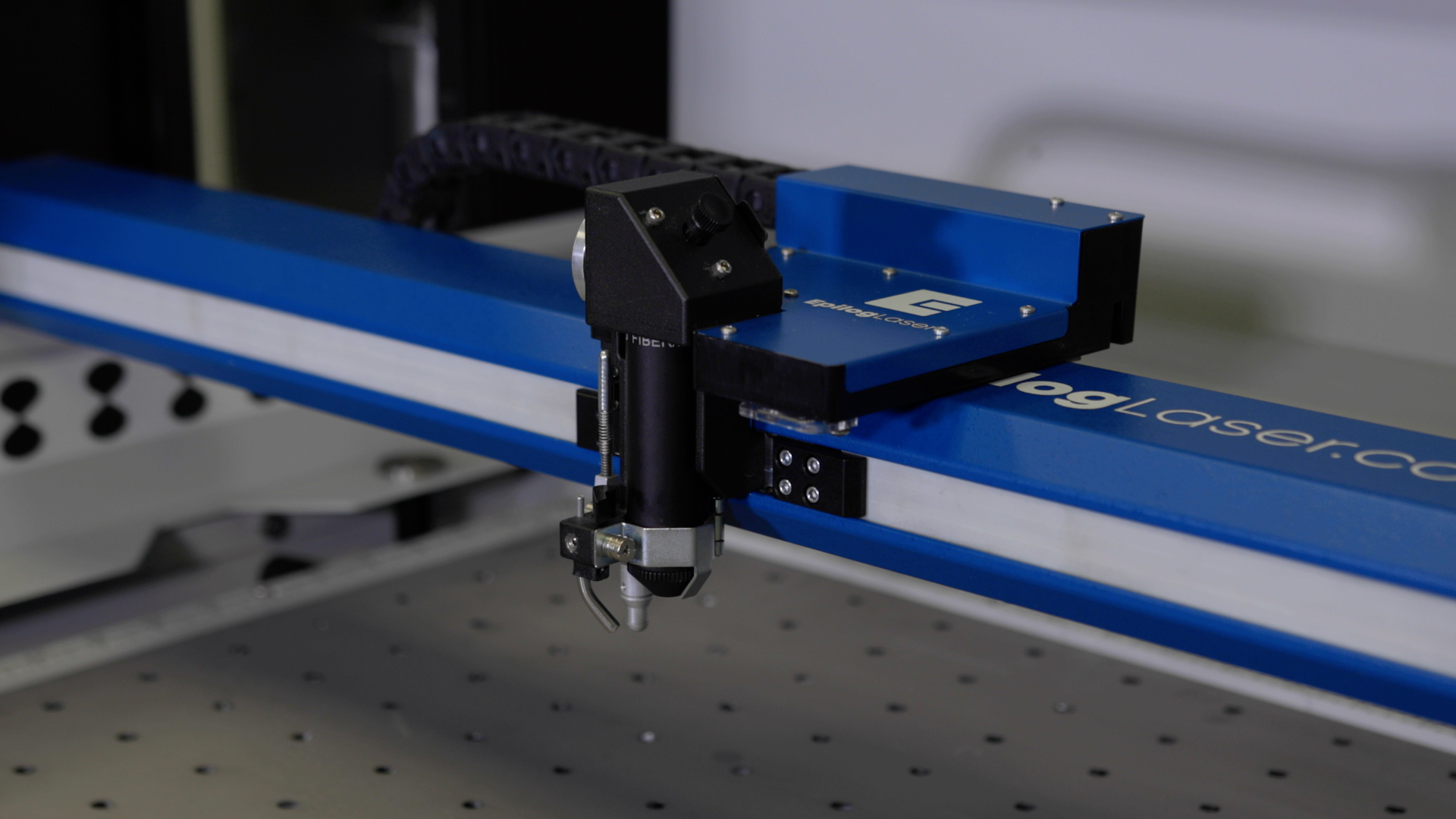
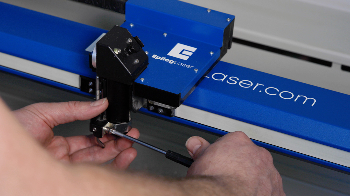
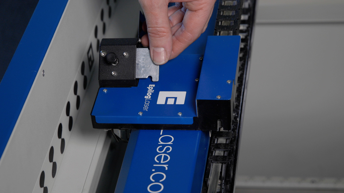
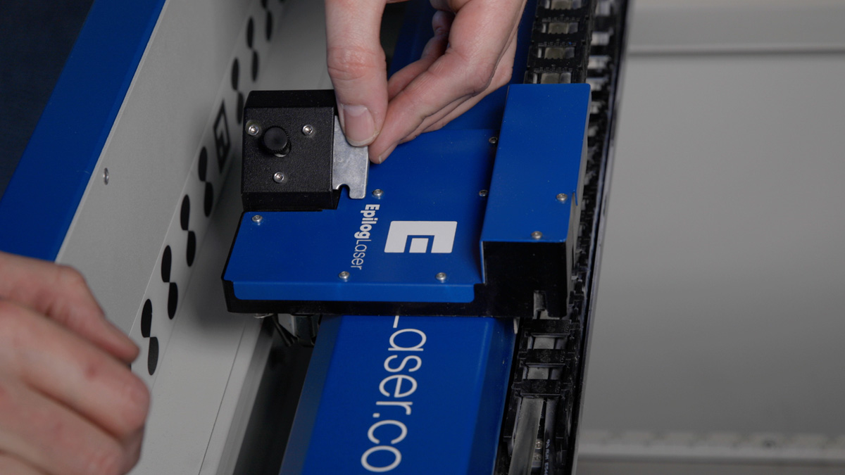
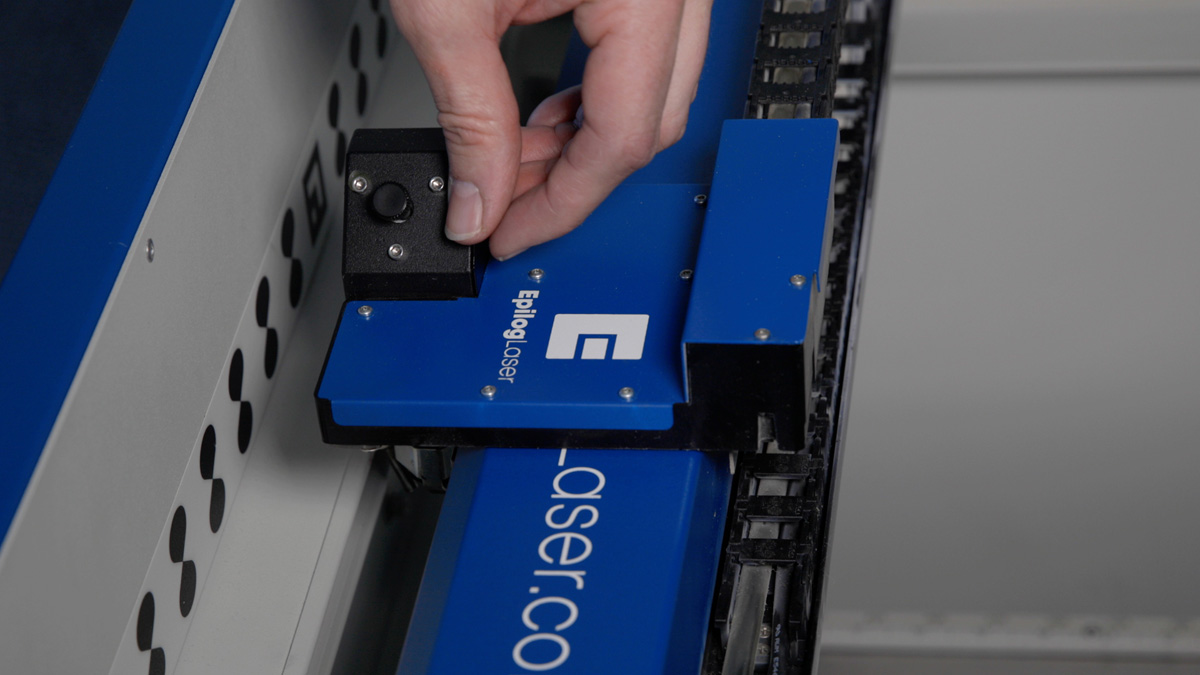
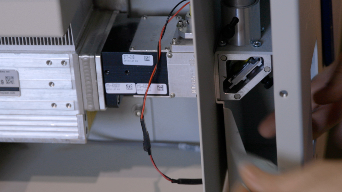
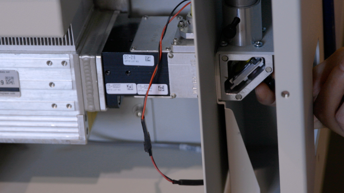
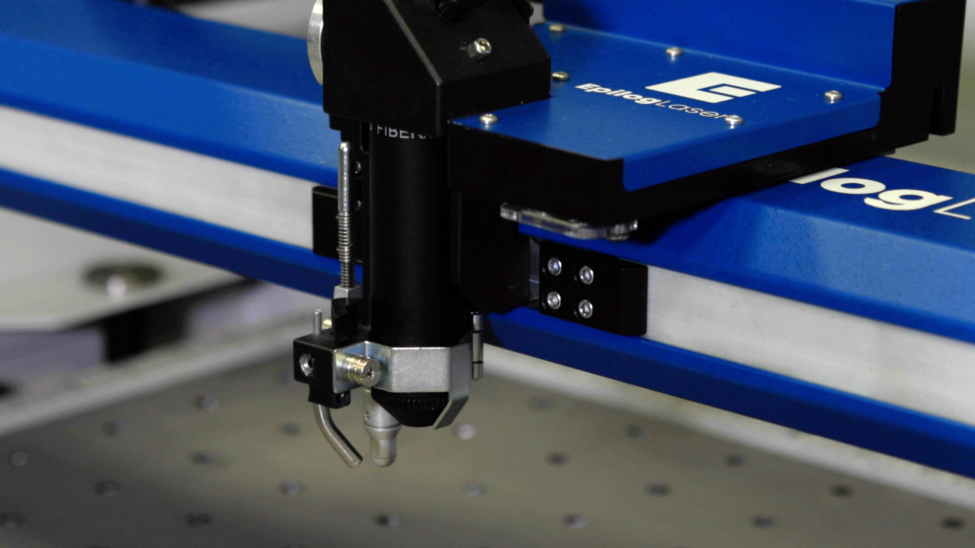
Remove the X-axis assembly from the machine.
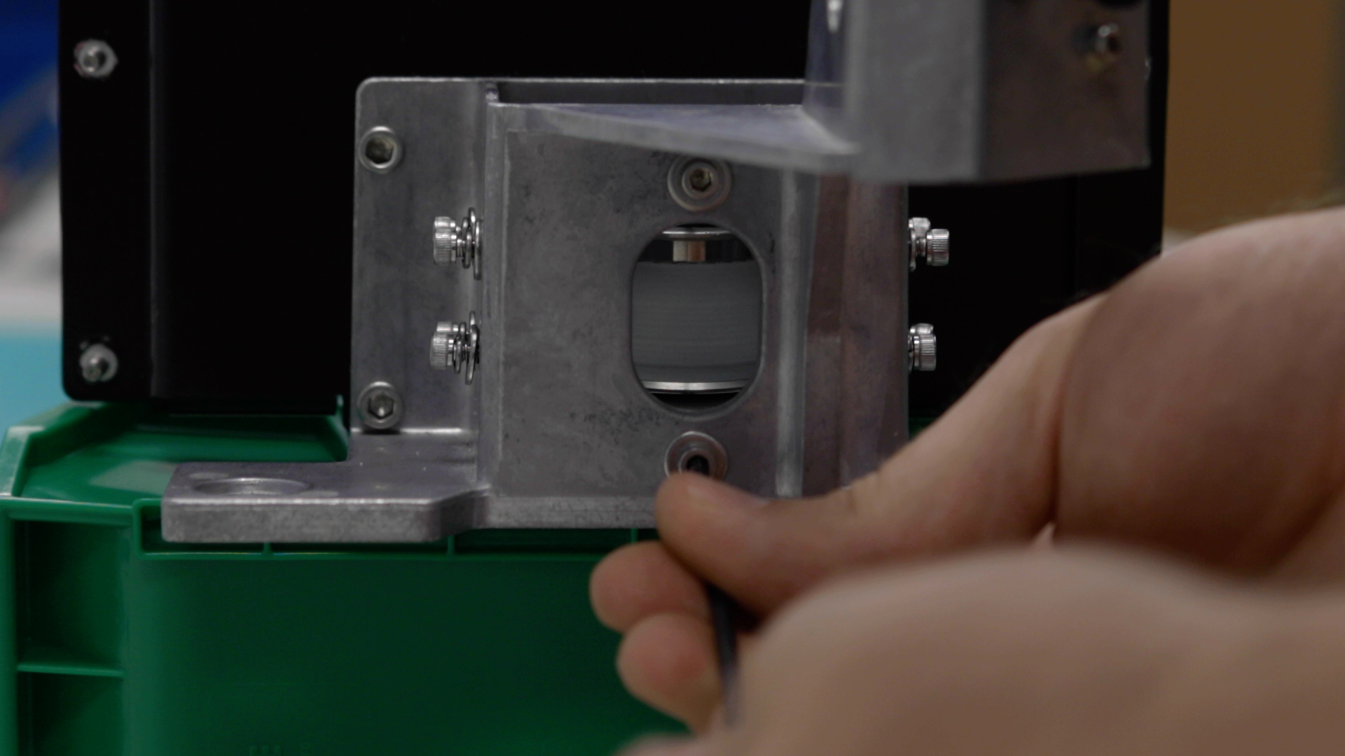
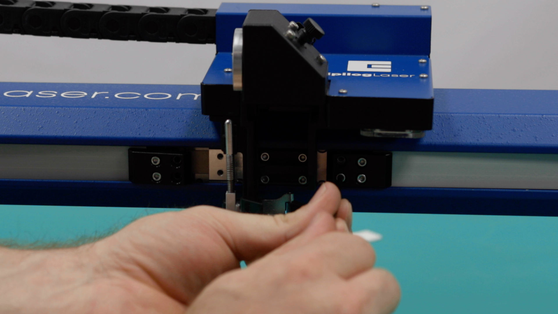
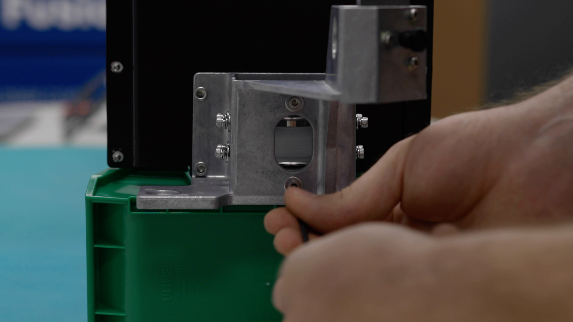
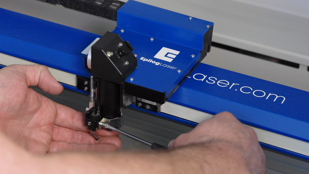
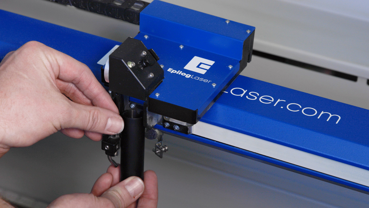
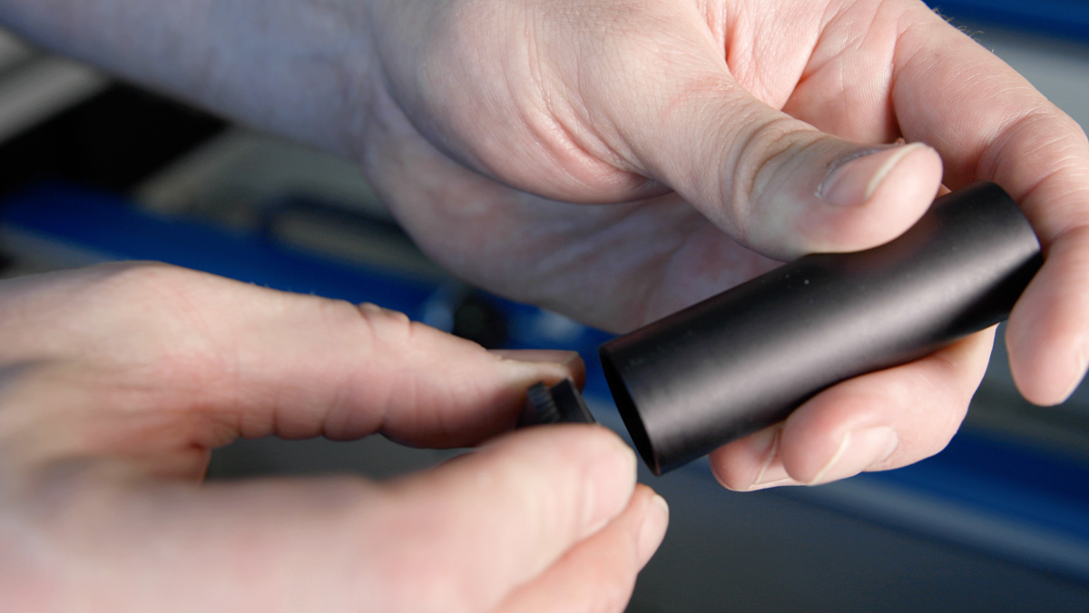
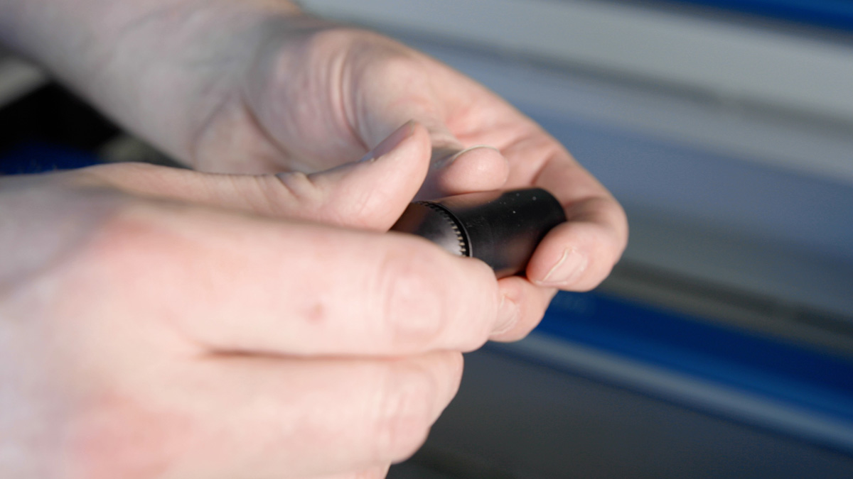
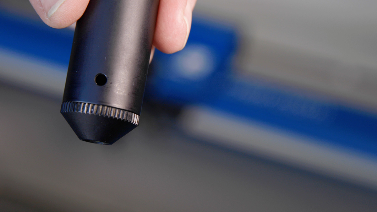
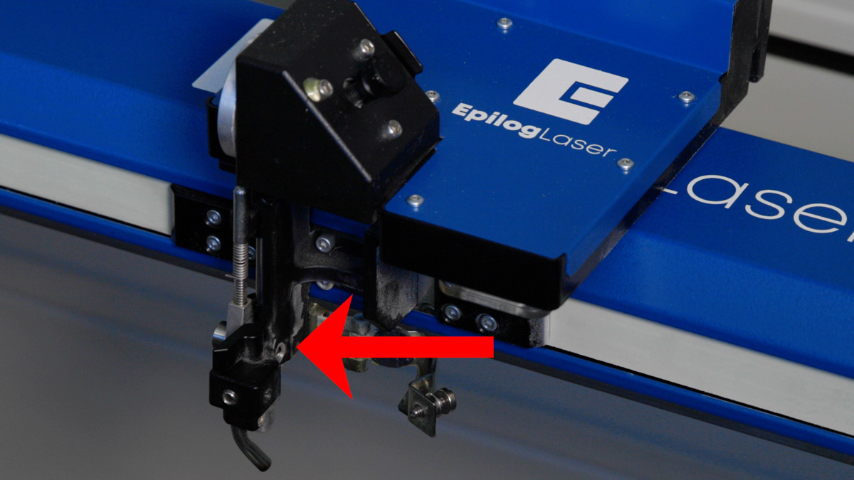
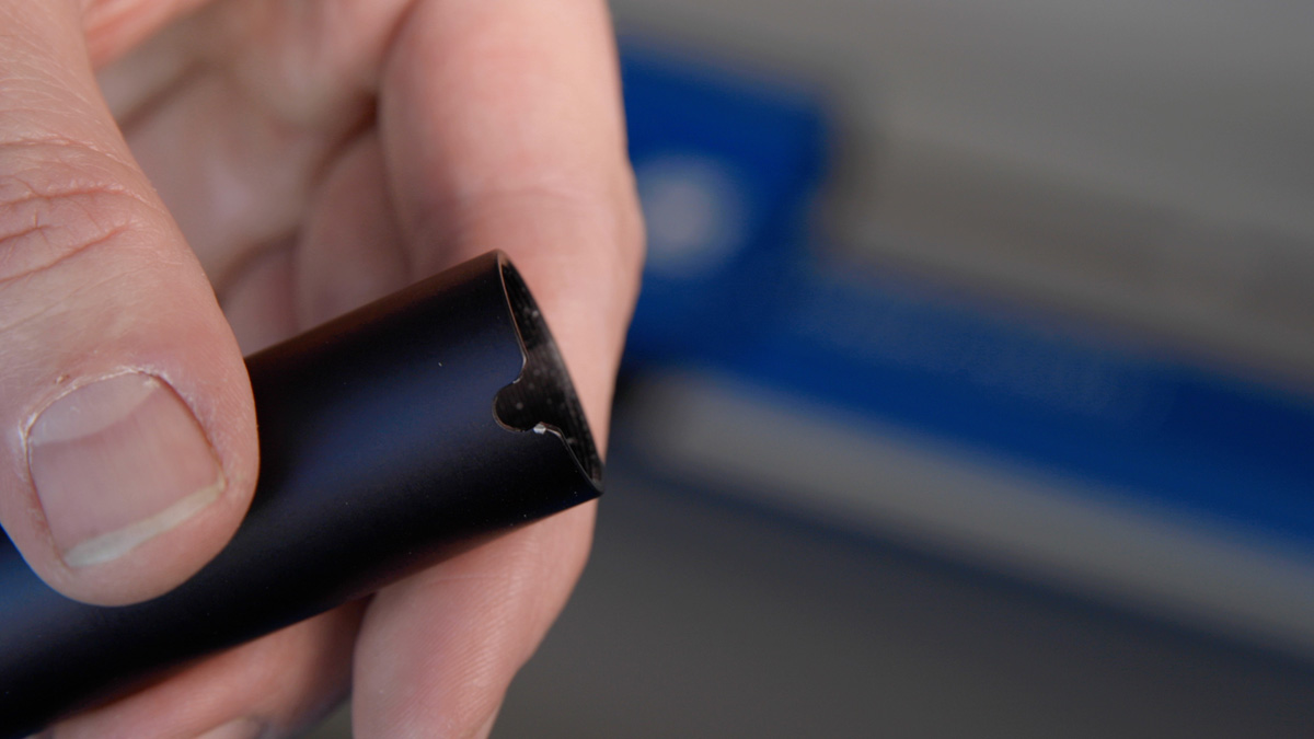
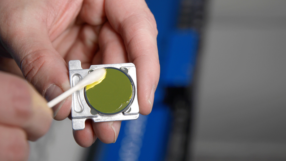
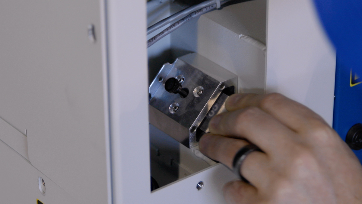
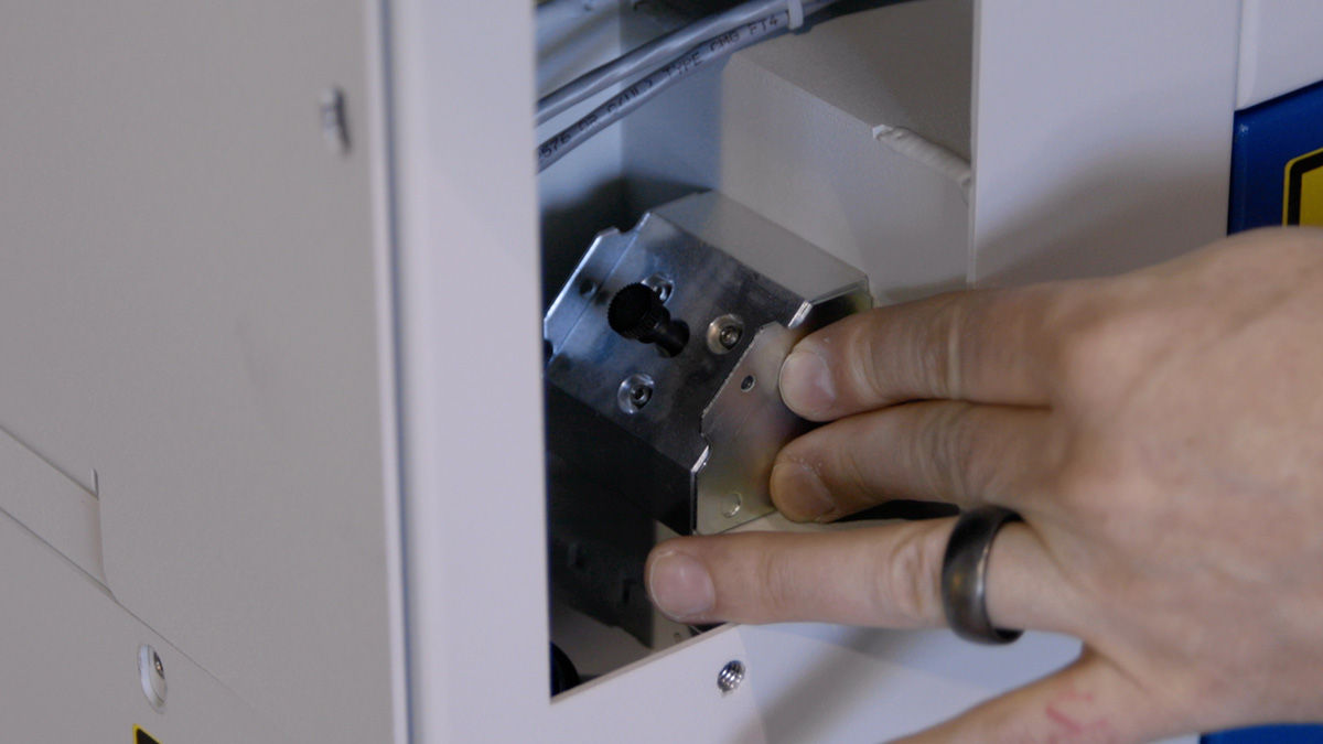
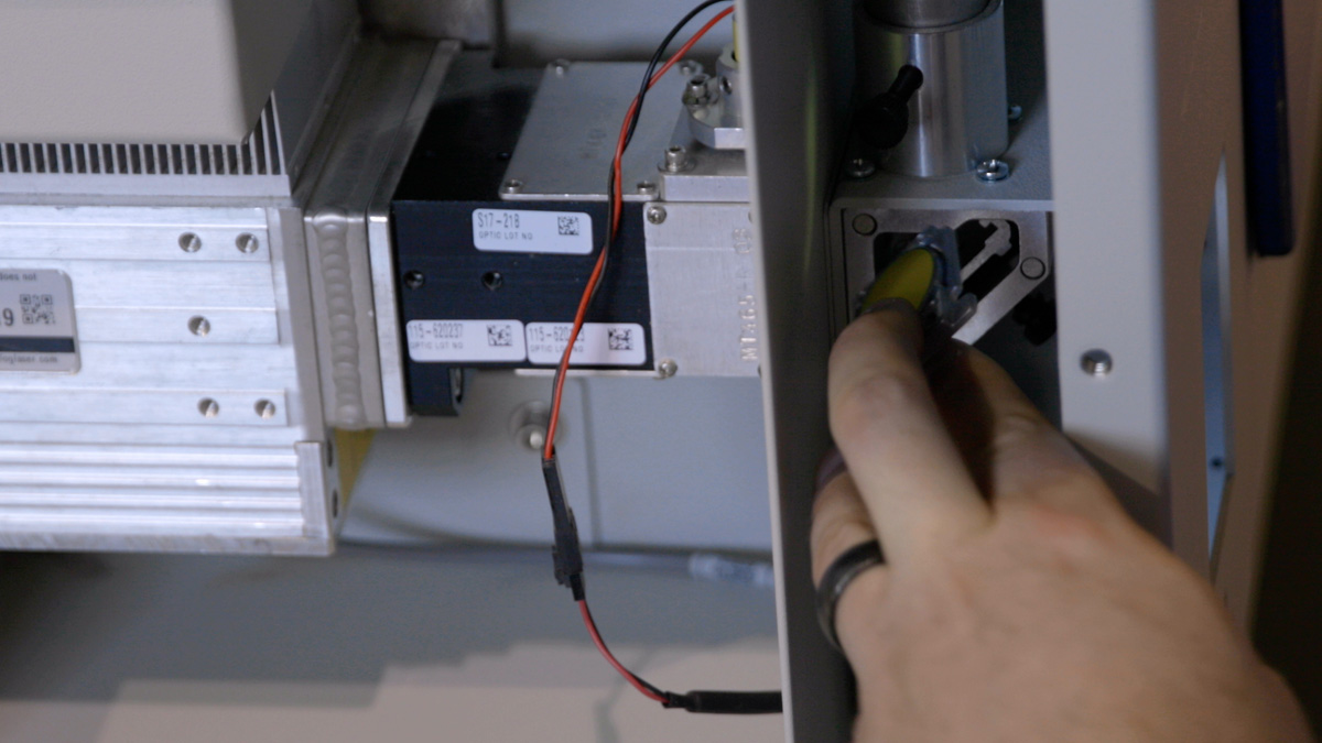
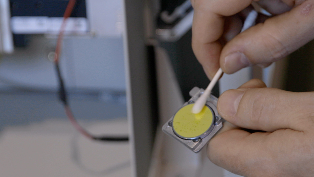
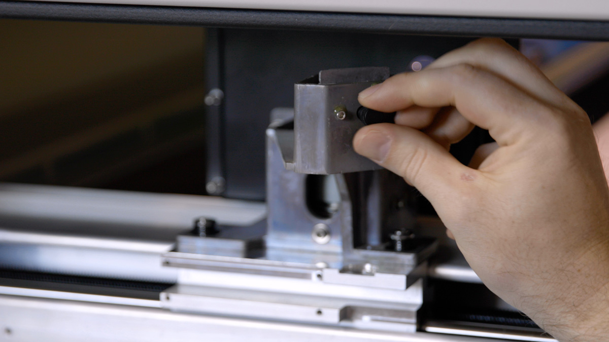
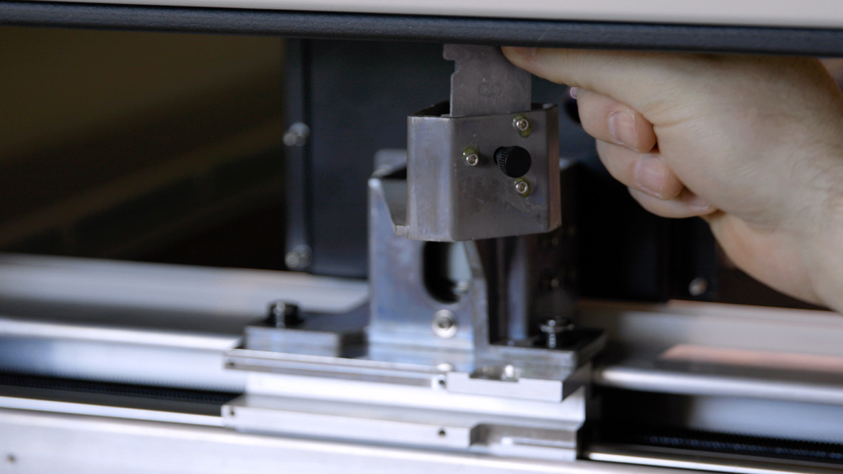
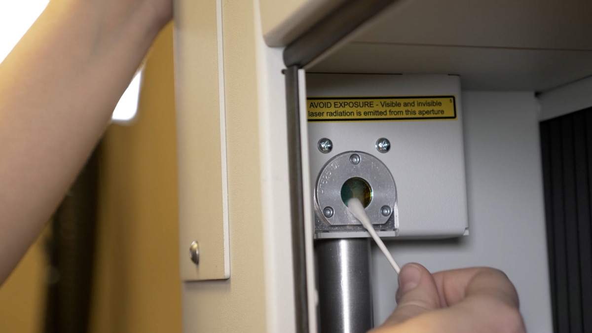
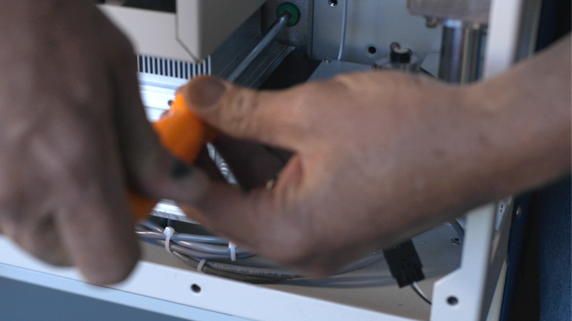
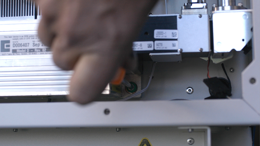
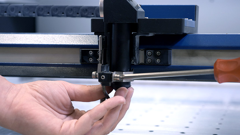
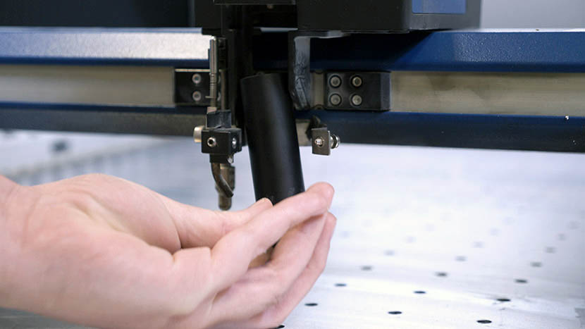
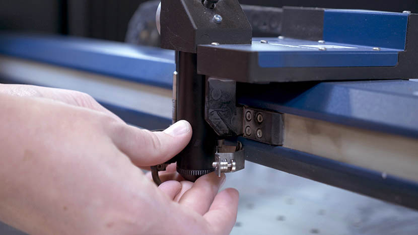
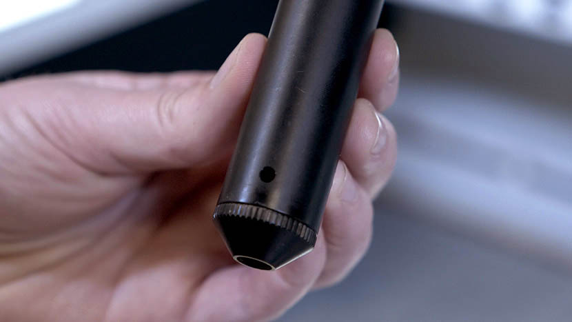
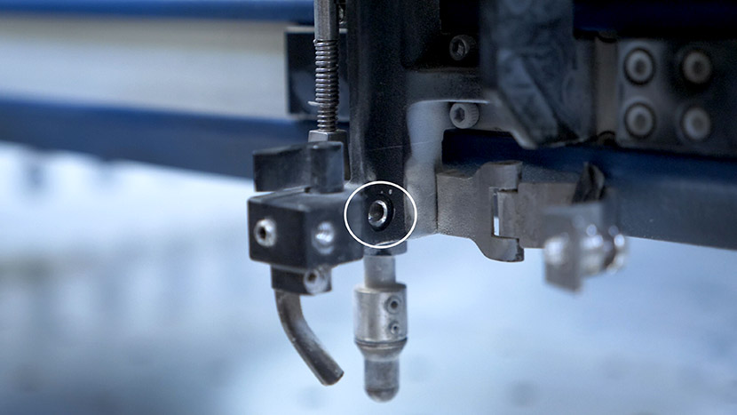
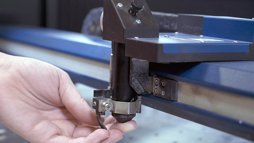
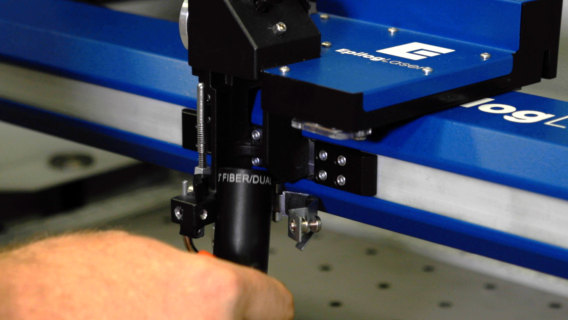
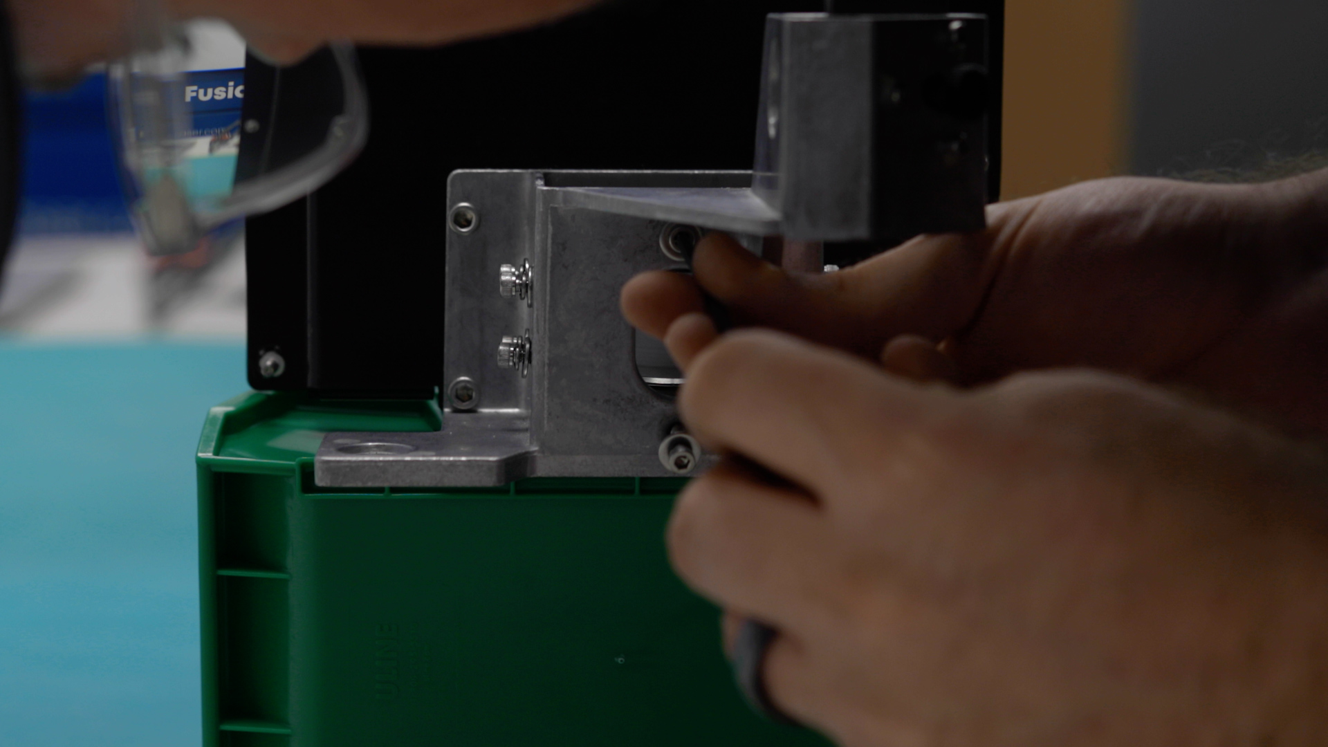
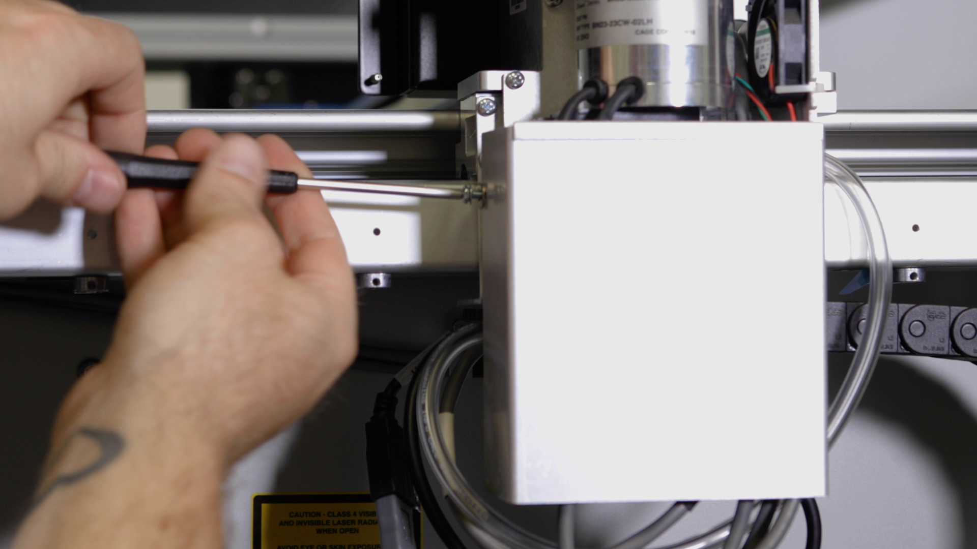
Remove the lens tube by using a Philips head screwdriver to unscrew the captive screw securing the front lens clamp.
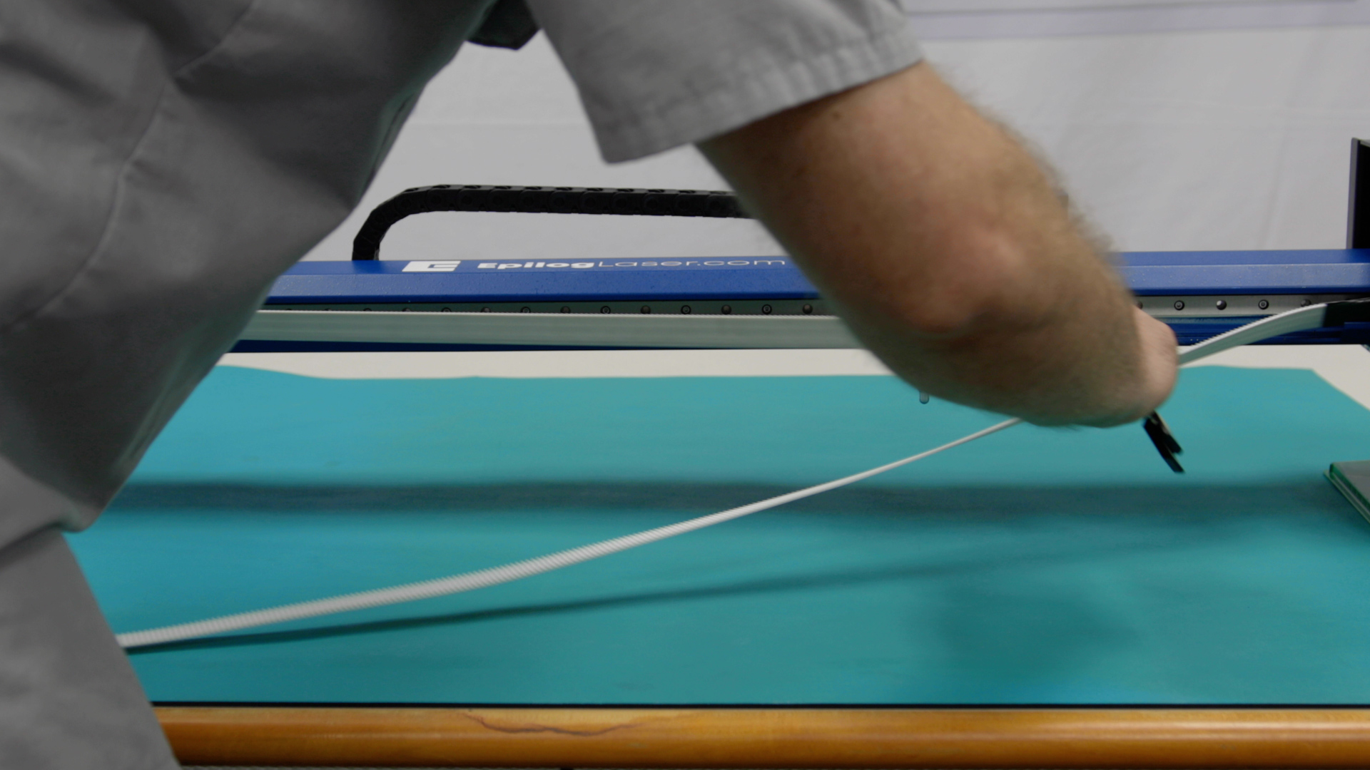
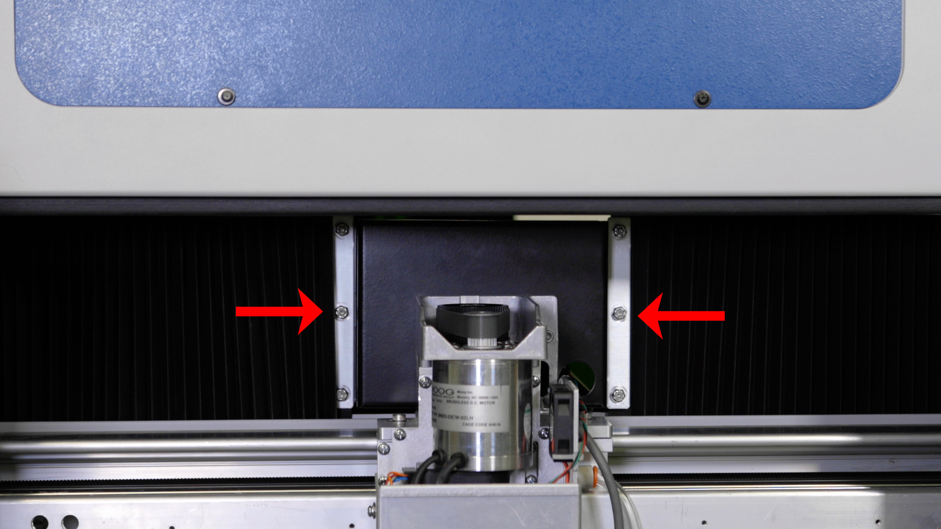
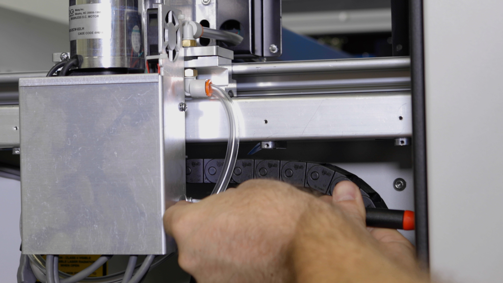
Remove the left and right bellows on both sides of the machine by loosening the six (6) 5/16” nuts which secure them in place.
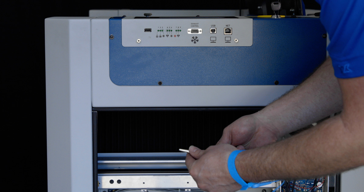
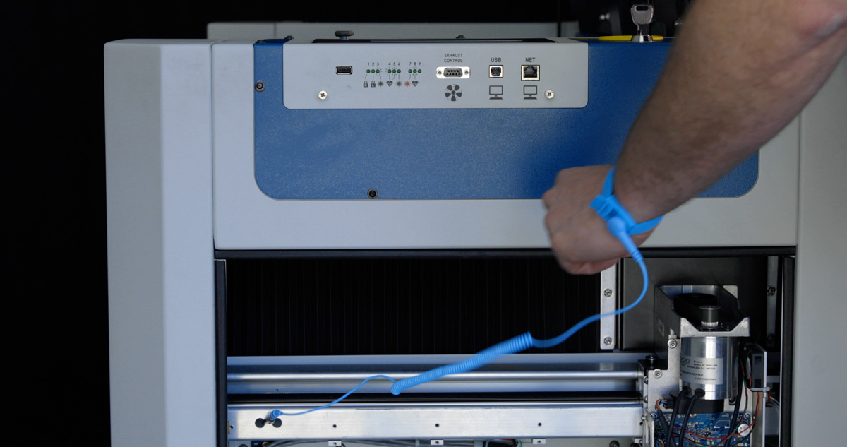
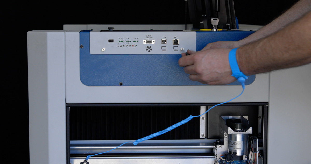
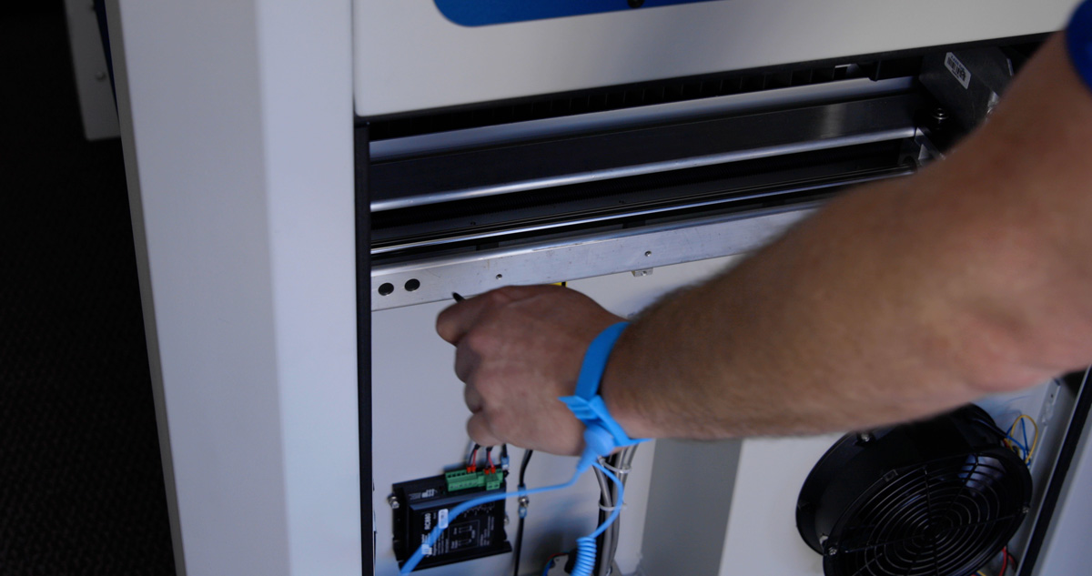
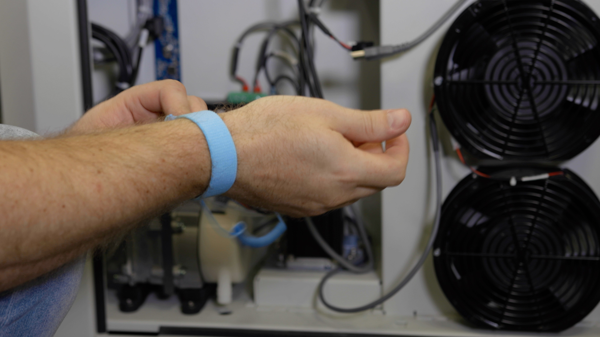
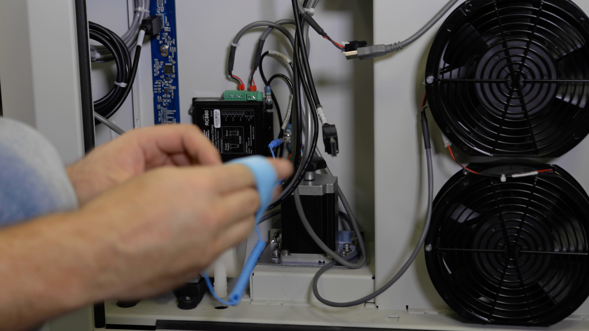
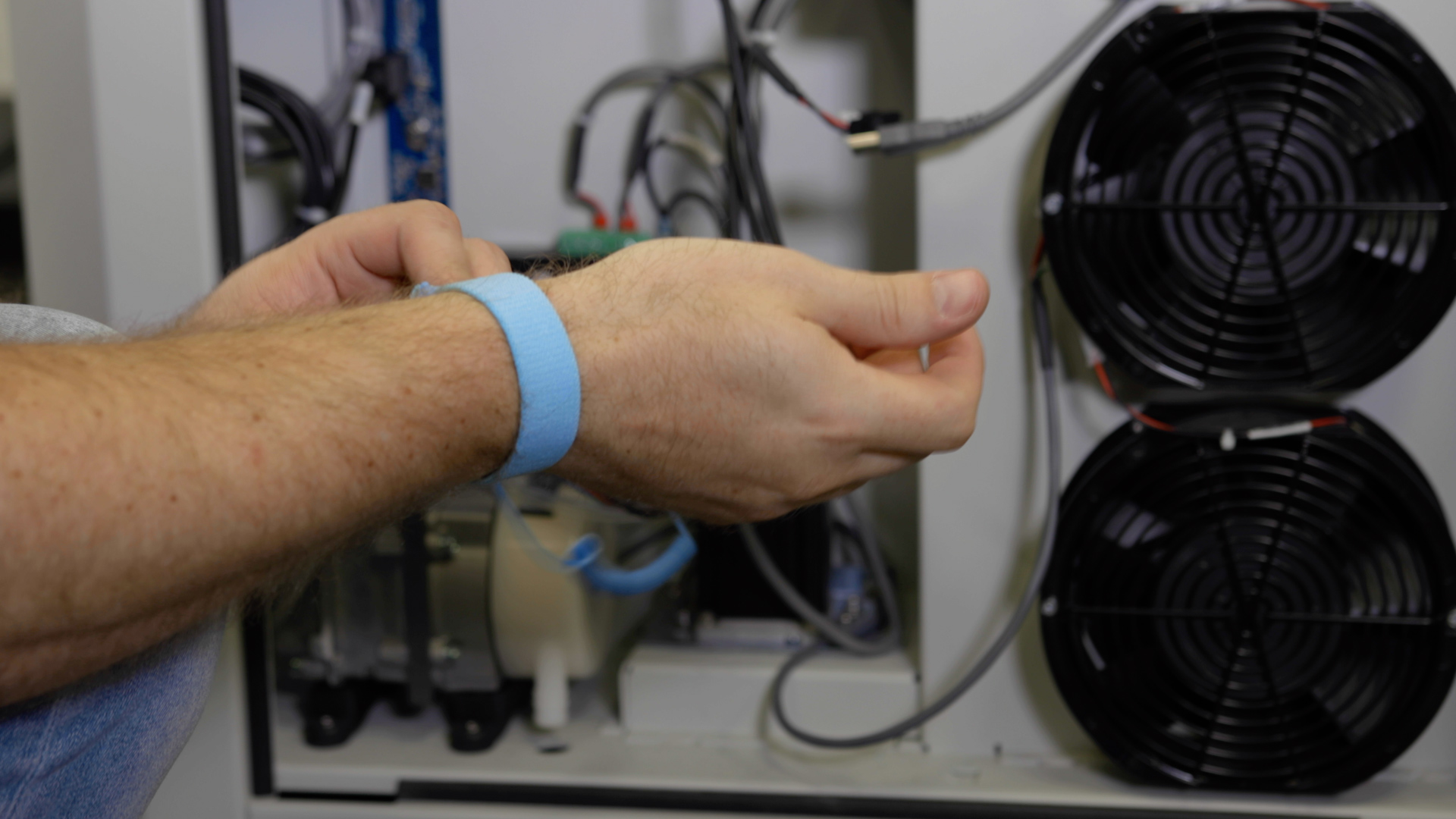
Put on the anti-static wrist strap. Clip the strap on to any metal part of the machine. Always wear the anti-static strap to avoid damaging the unit through static discharge.
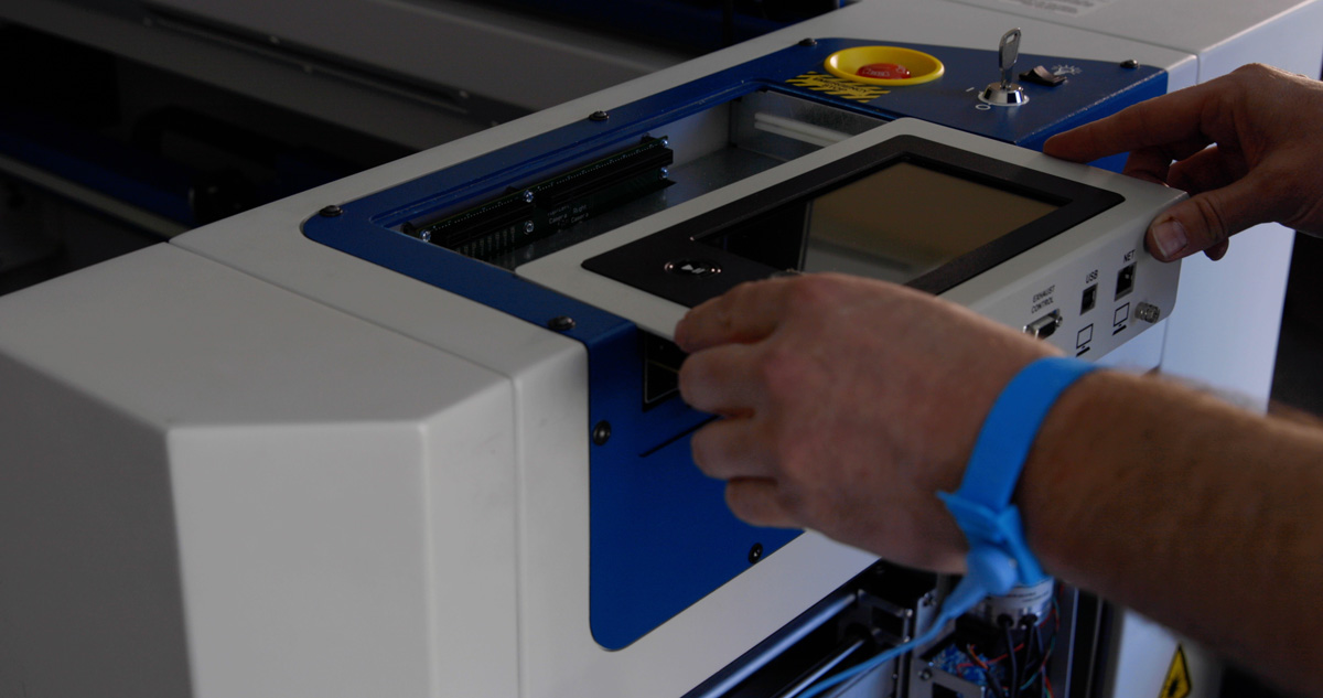
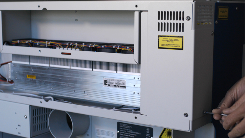
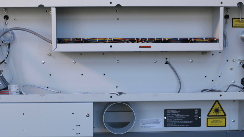
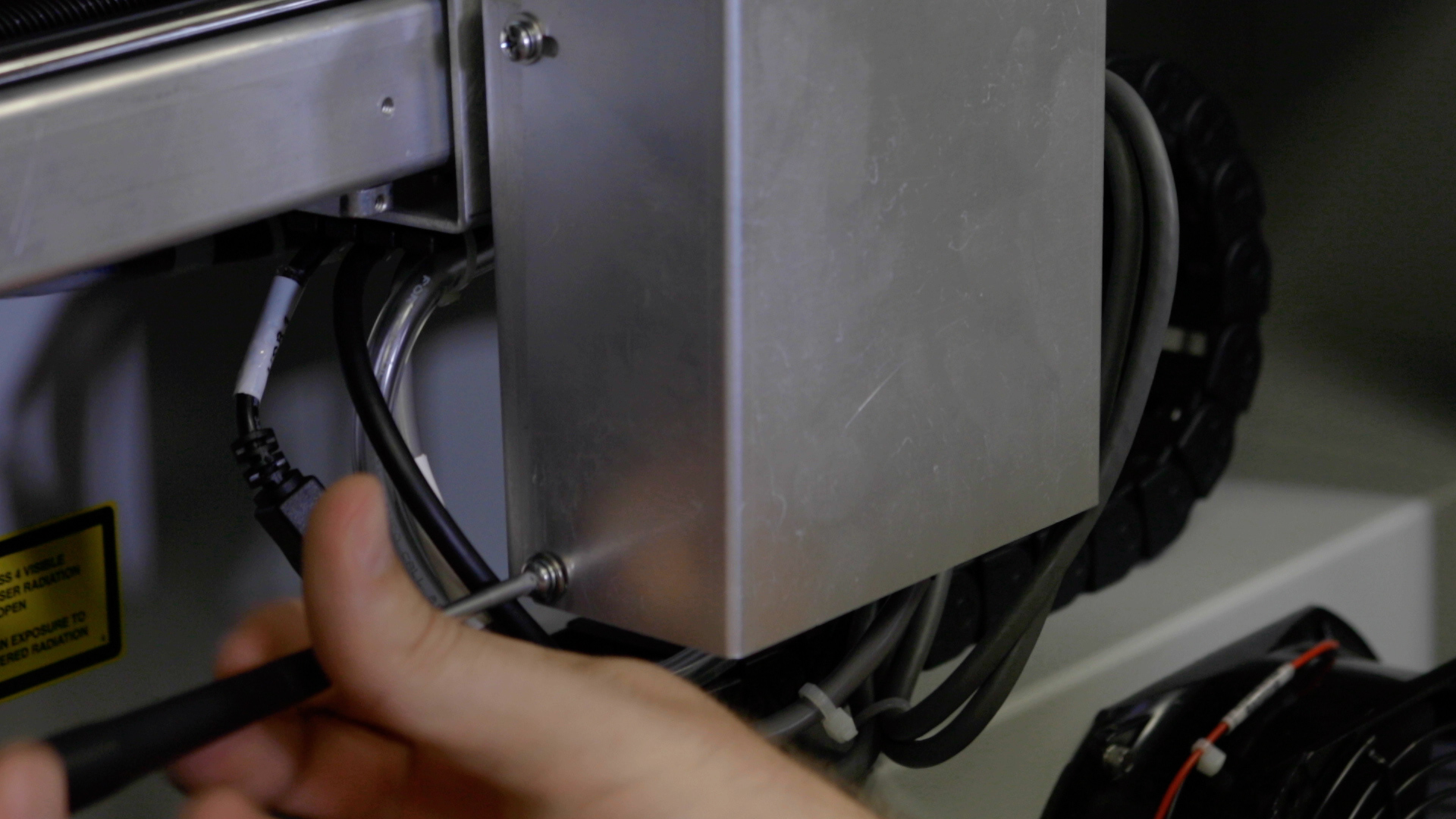
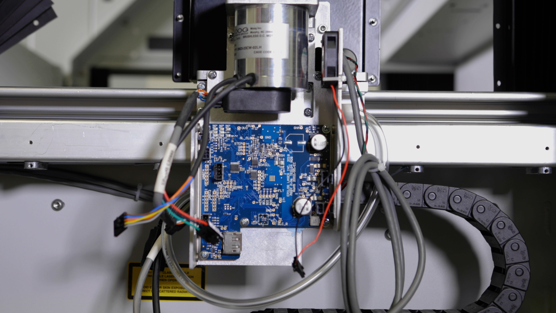
Using a Phillips screwdriver, remove the 4 screws that secure the x-axis motor drive board cover and set the cover to the side.
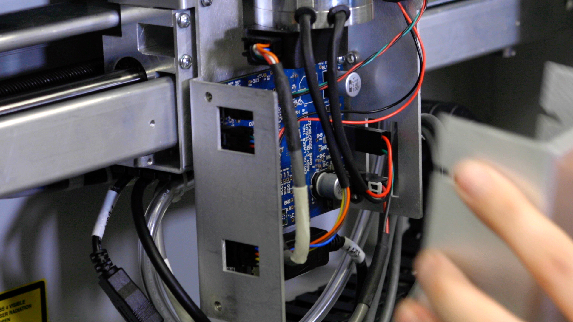
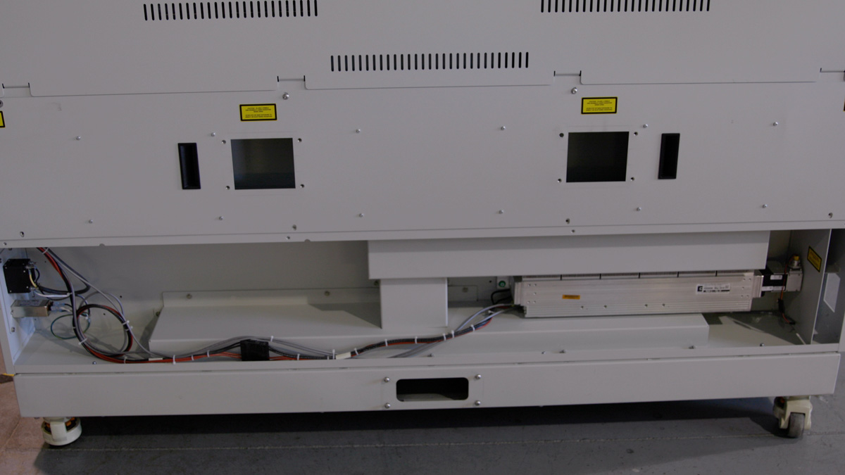
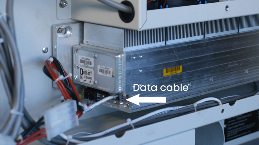
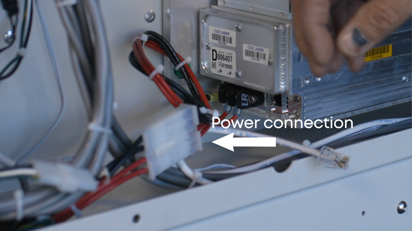
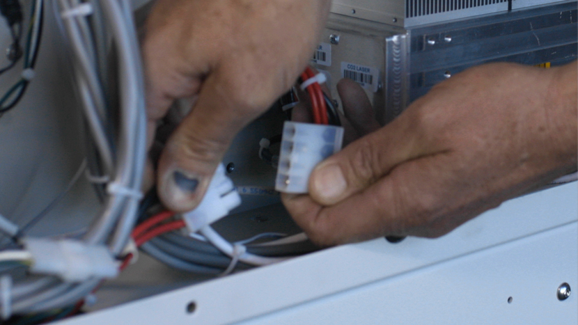
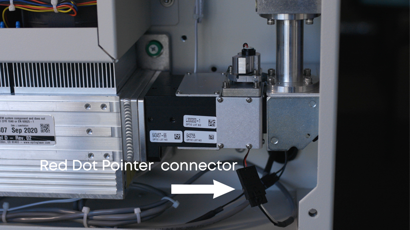
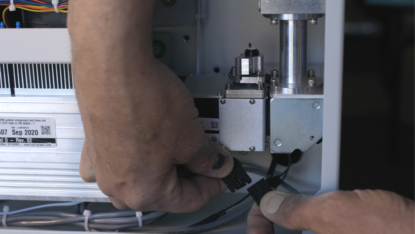
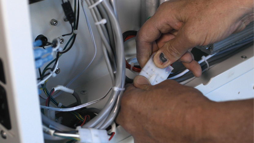
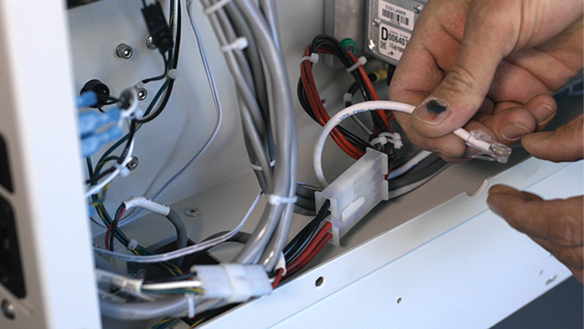
Now, disconnect the 7 electrical connectors from the drive board and set the board to the side.
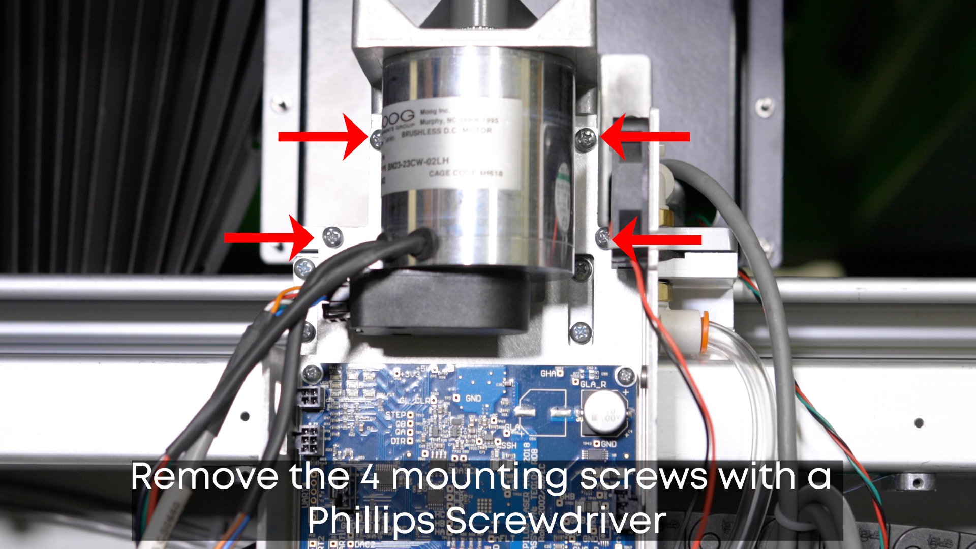
Remove the 4 mounting screws supporting the drive board using a Phillips Screwdriver.
Take off the anti-static wrist strap until needed when replacing the motor drive board.
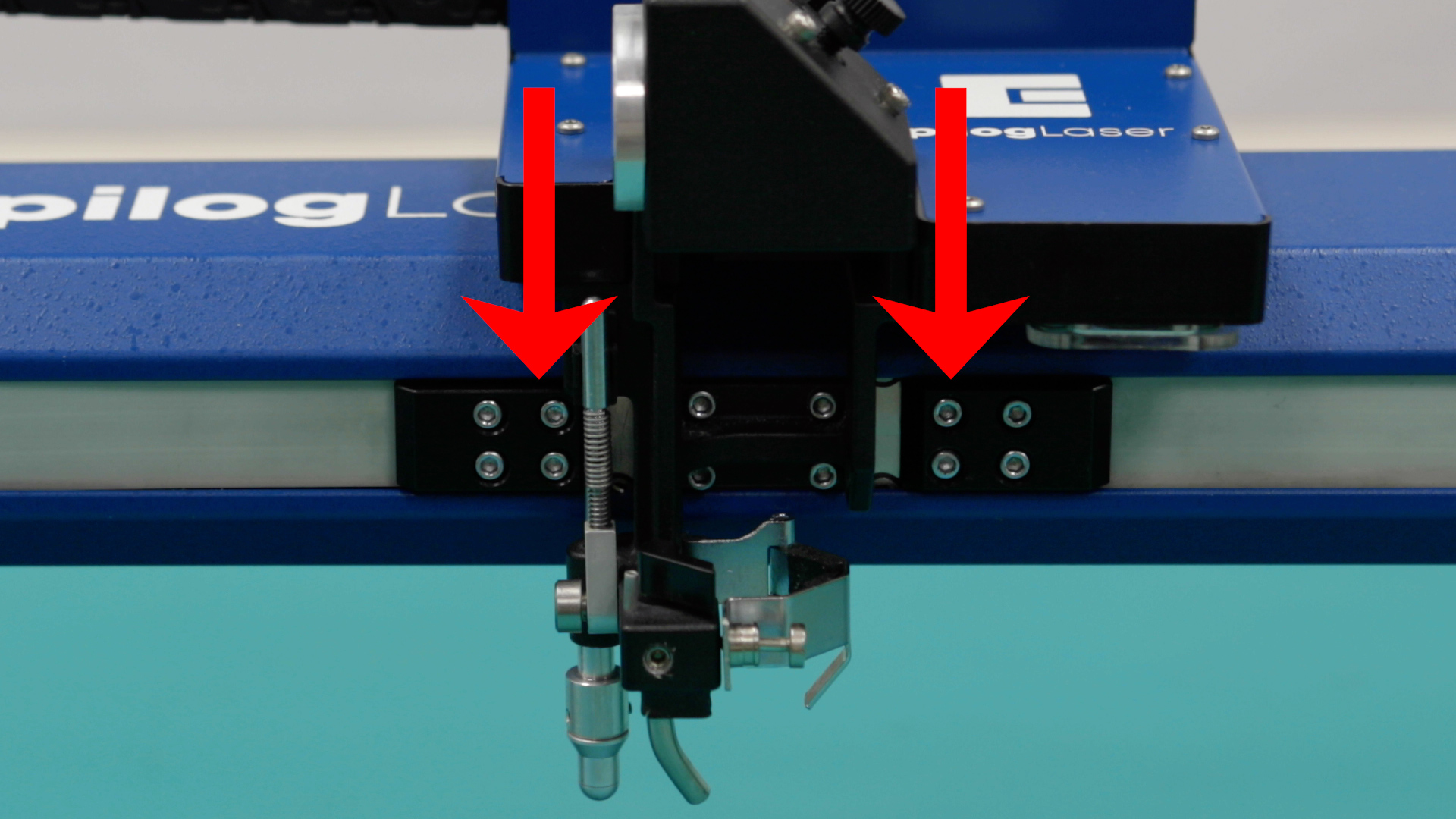
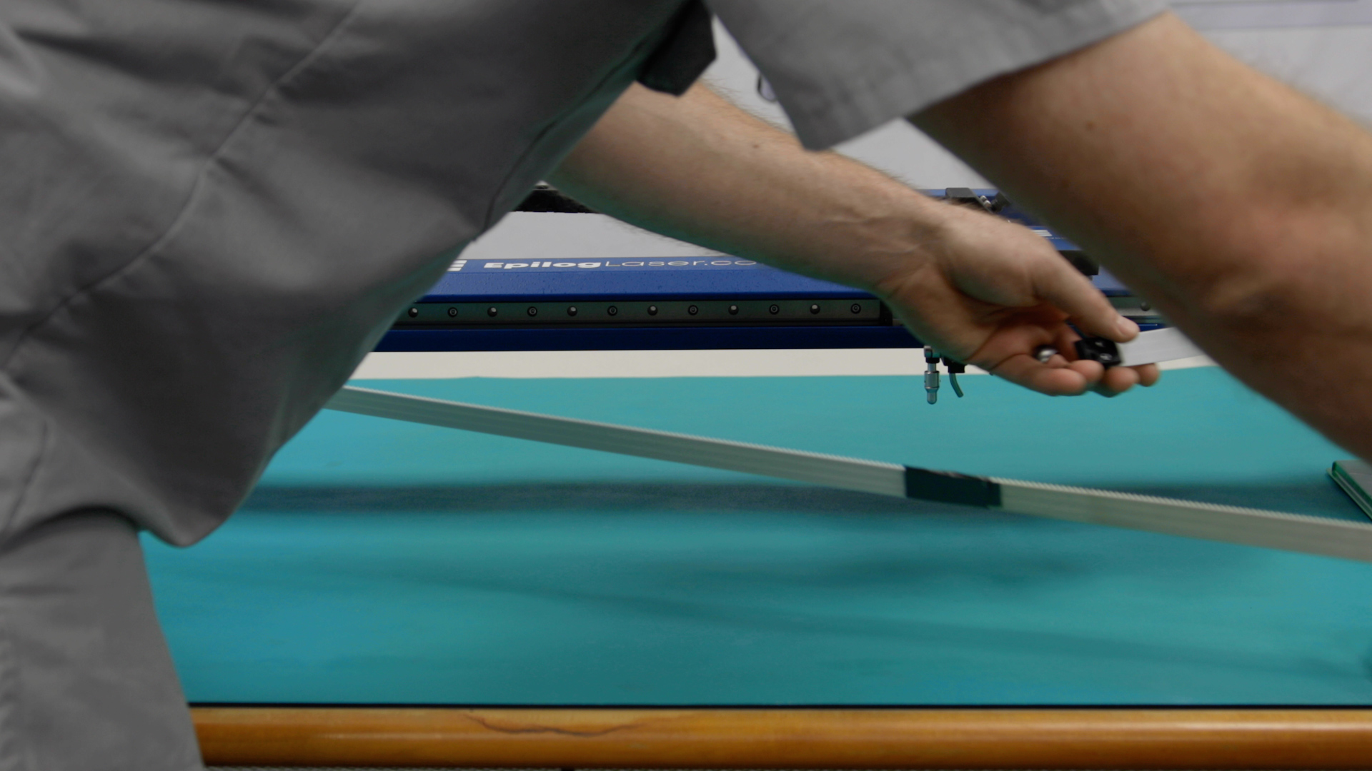
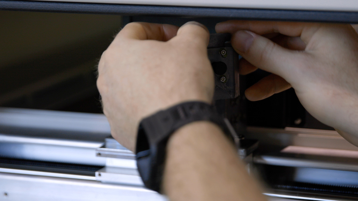
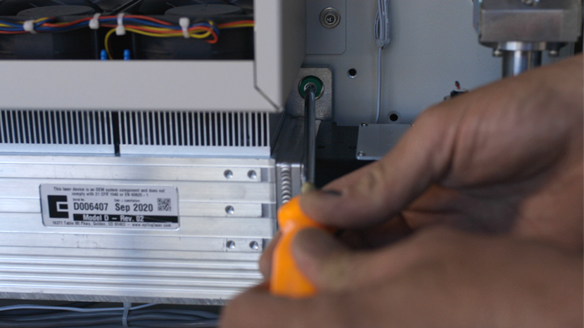
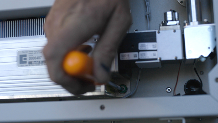
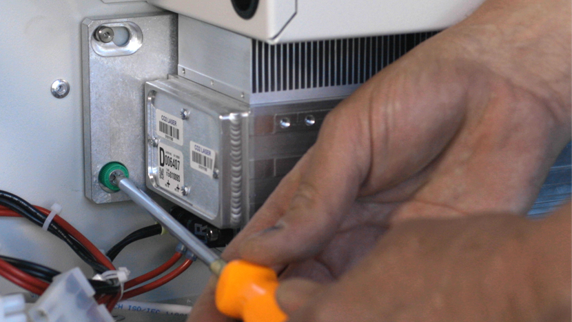
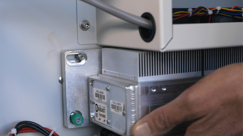
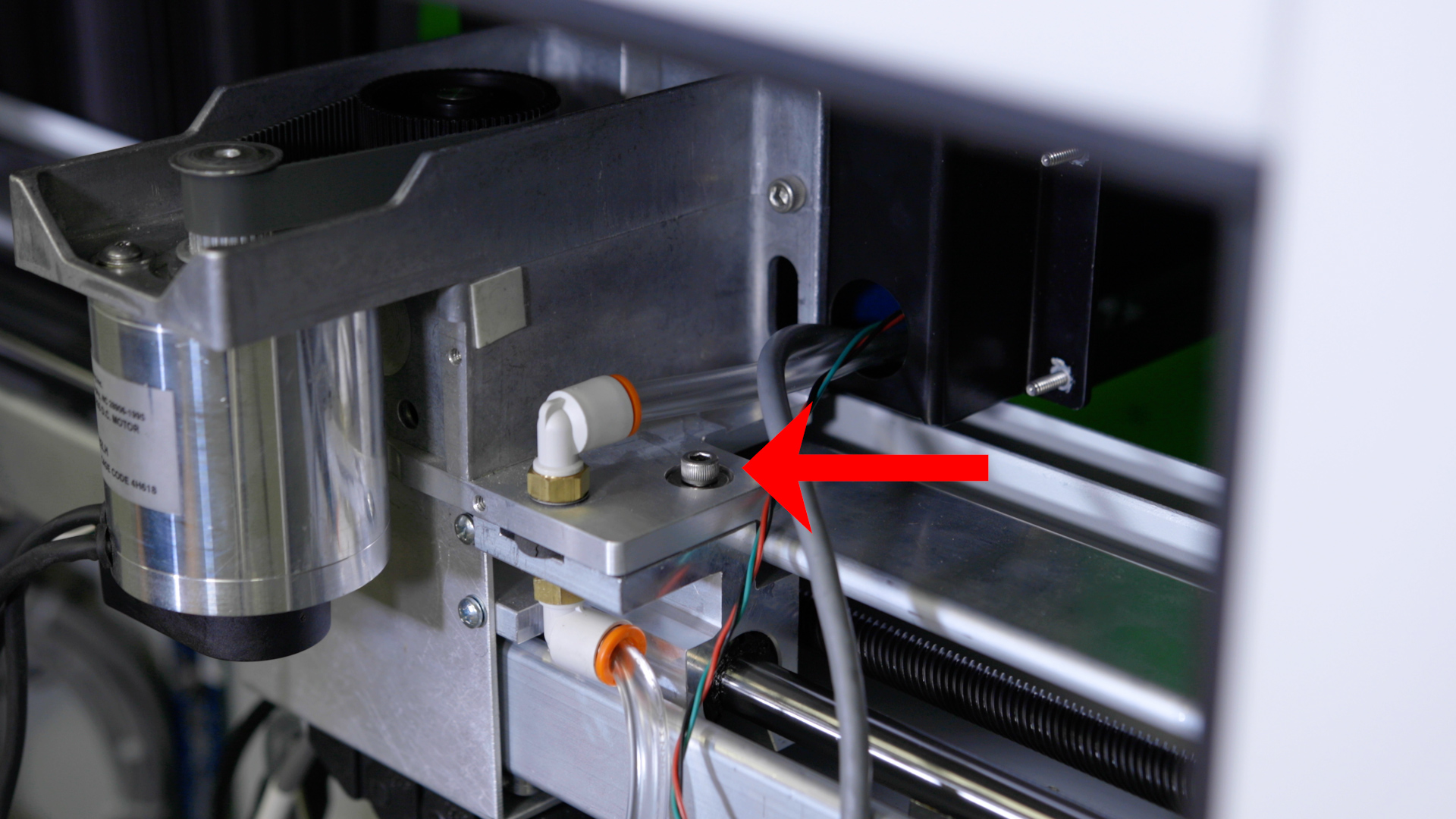
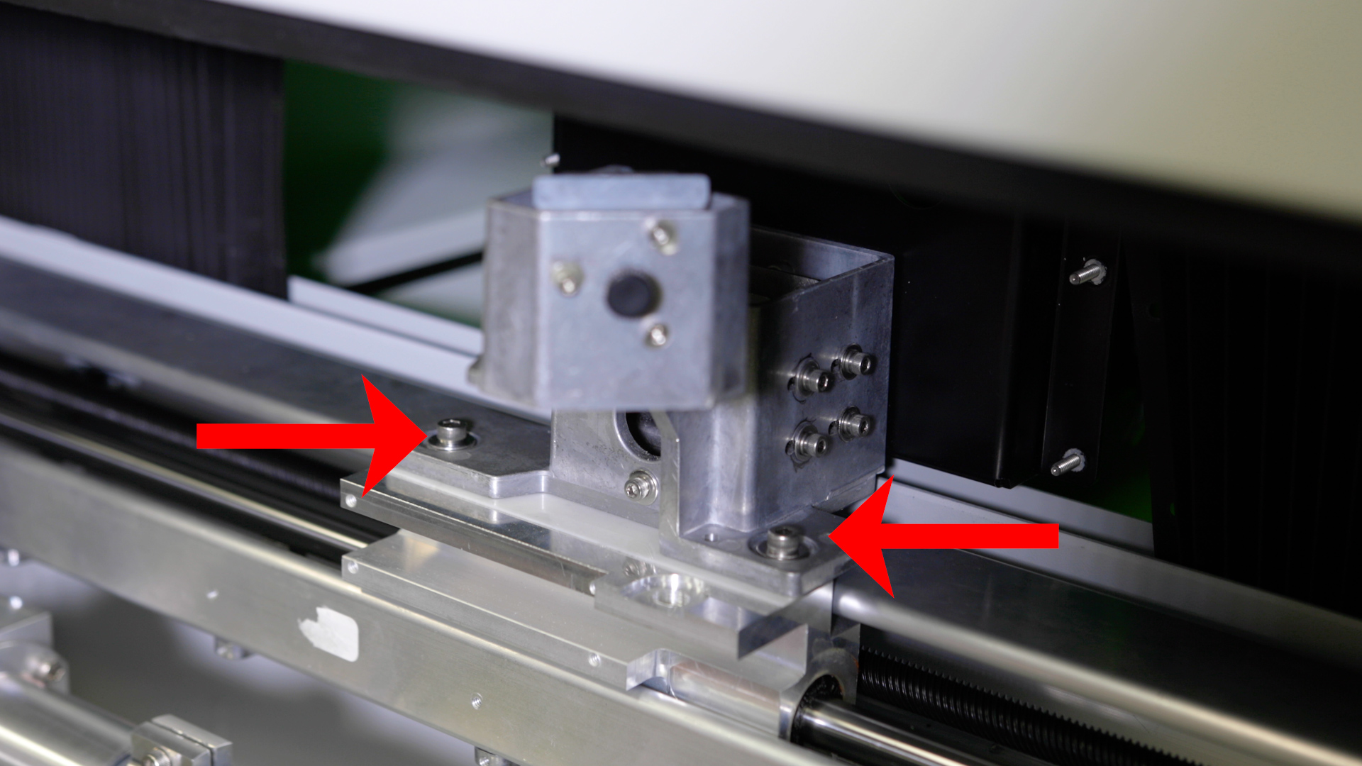
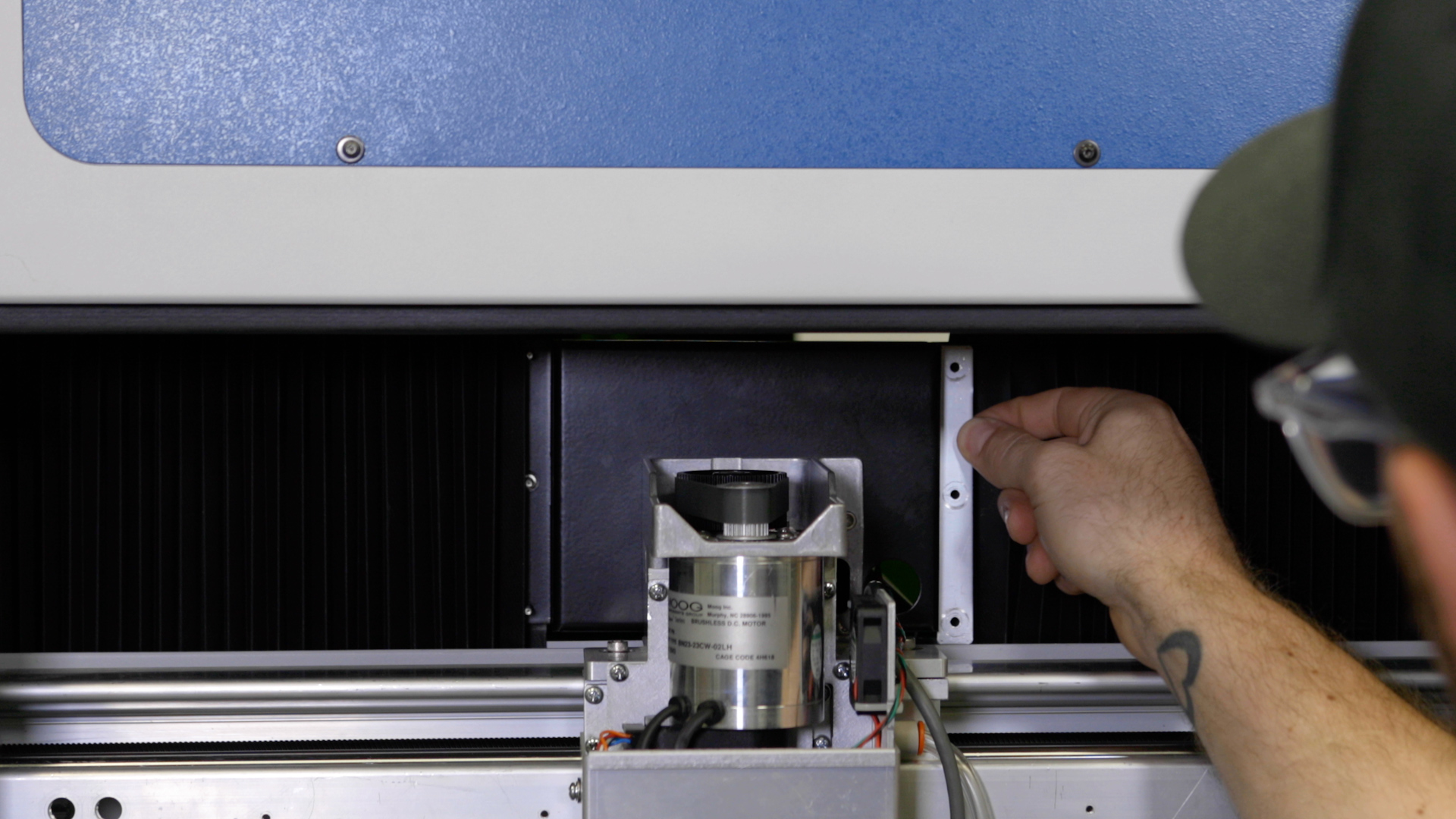
Remove the four 5/32” fasteners that secure the x-axis assembly to the y-axis bearings. There are two on the right side and two on the left side.

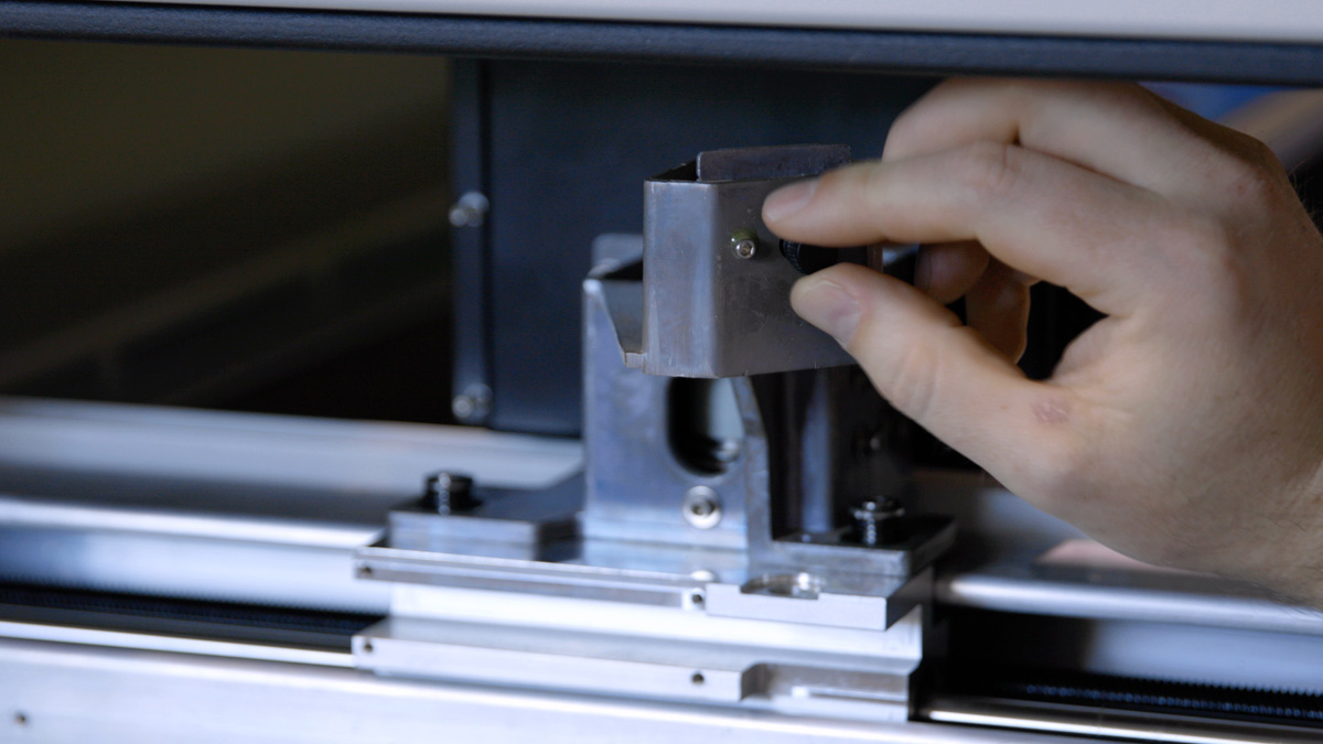
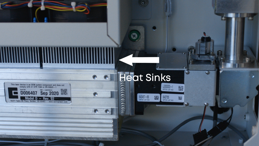
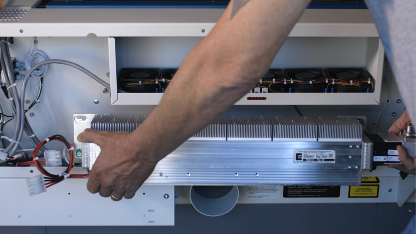
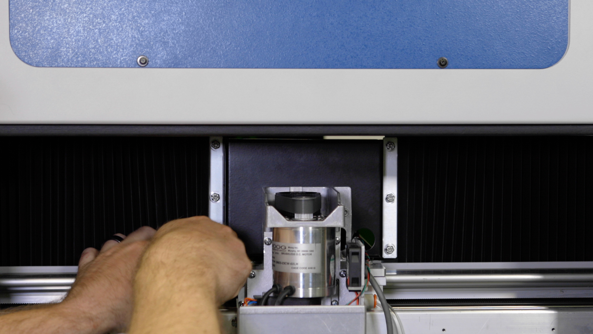
Slide the x-axis assembly out of the engraver through the right side of the machine, taking care to clear the carriage assembly through the opening without damage.
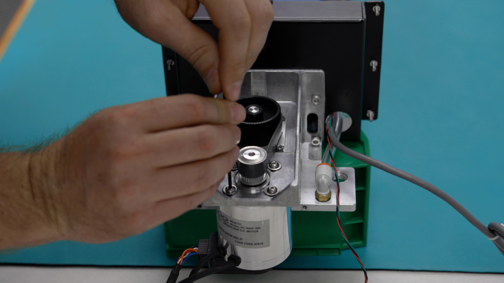
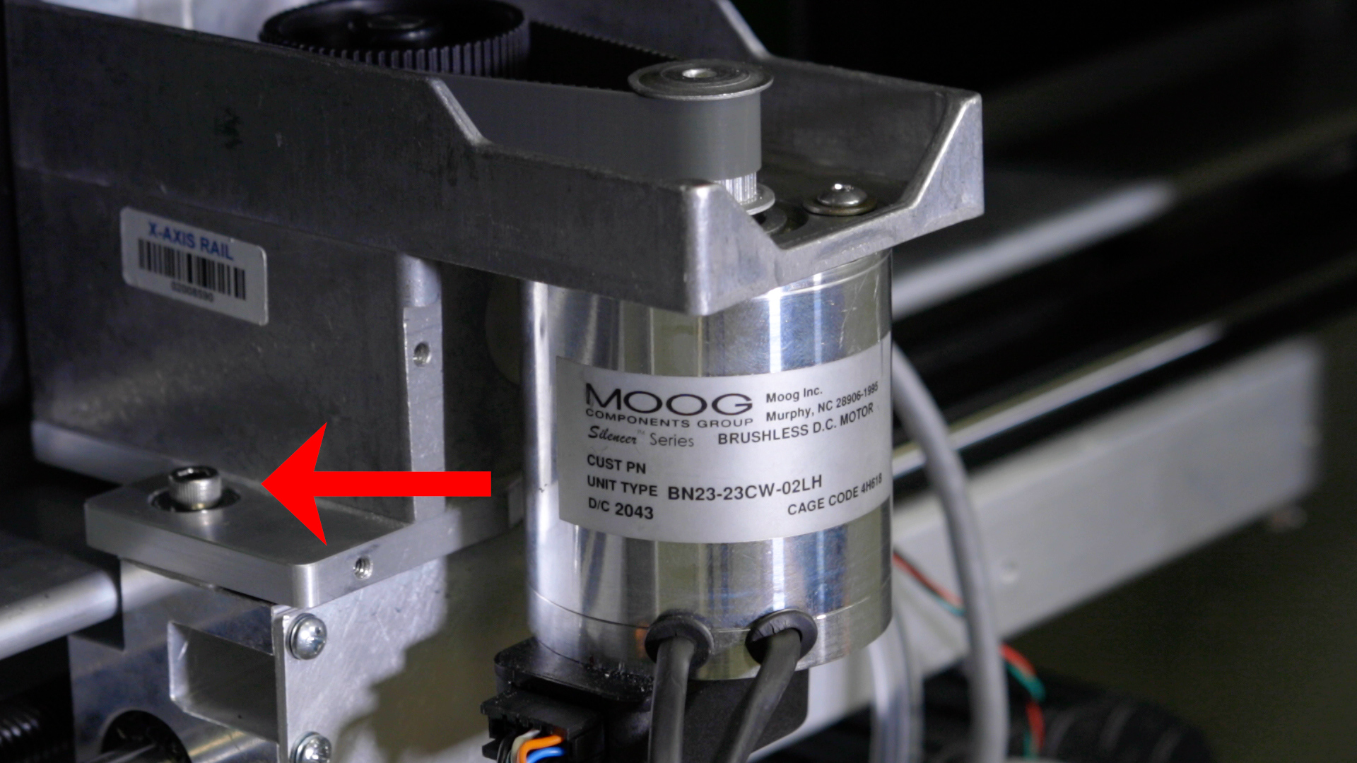
Loosen the four 2.5 mm x-axis motor mounting screws and move the x-axis motor towards the center of the x-axis assembly.
Remove the X-Axis Reducer Belt
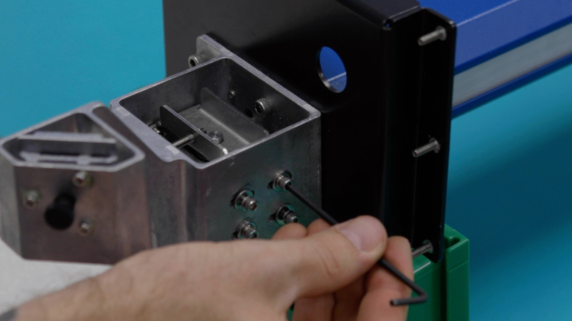
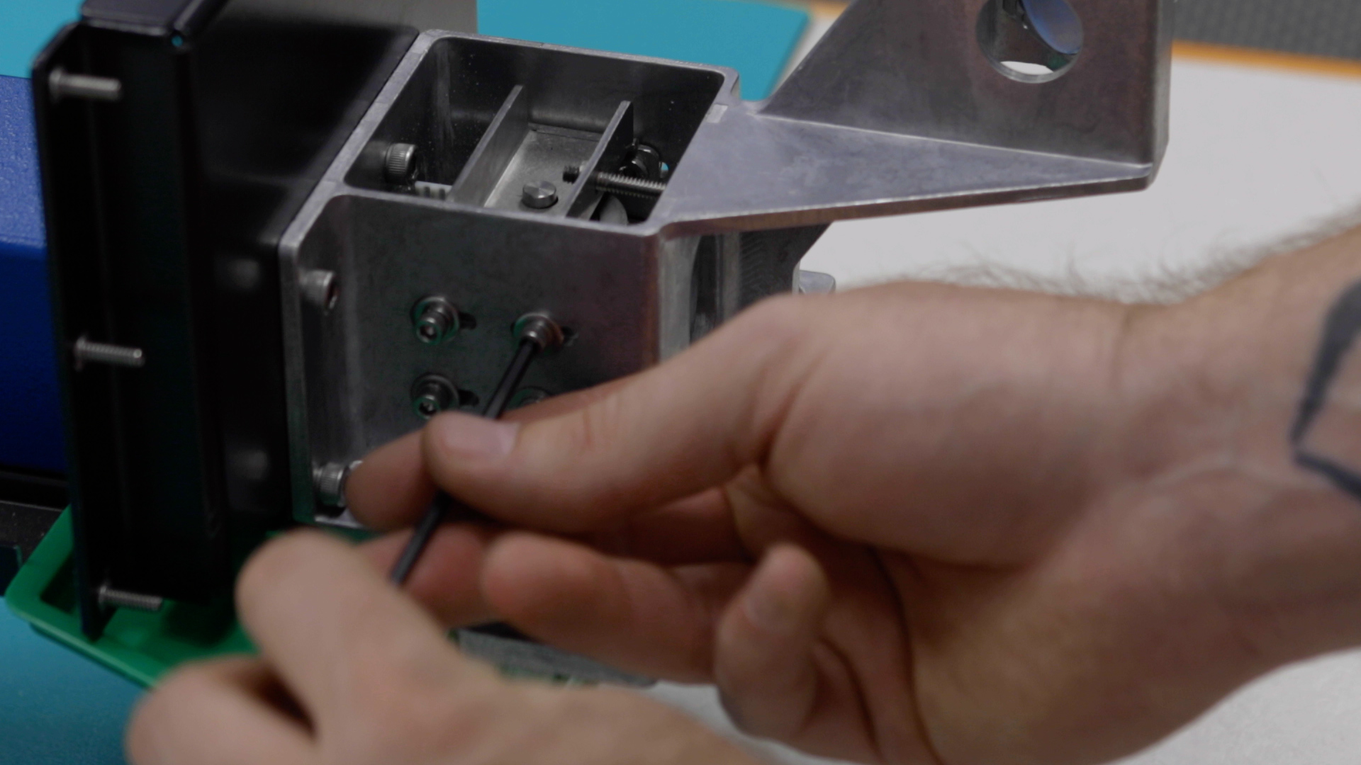
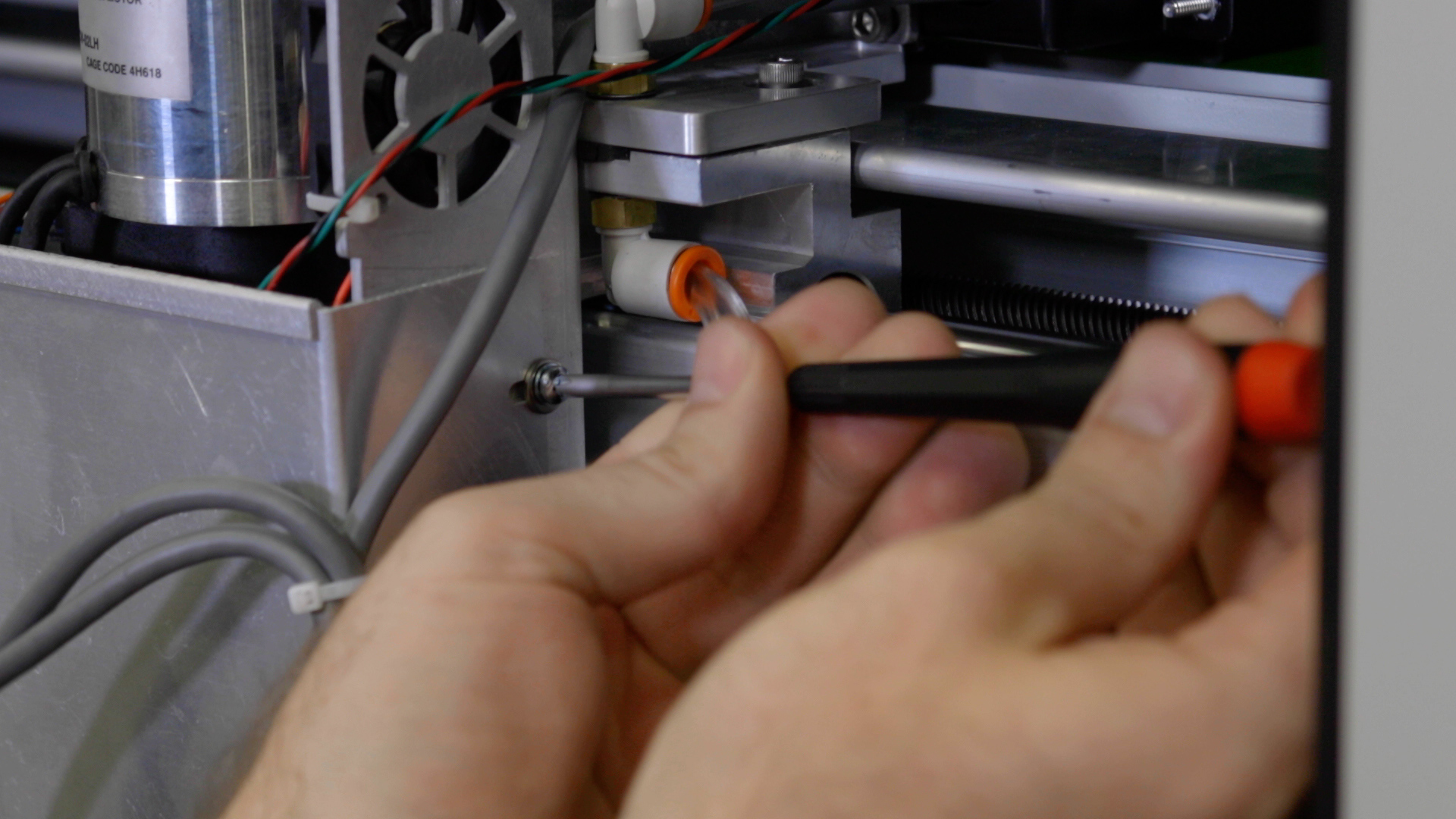
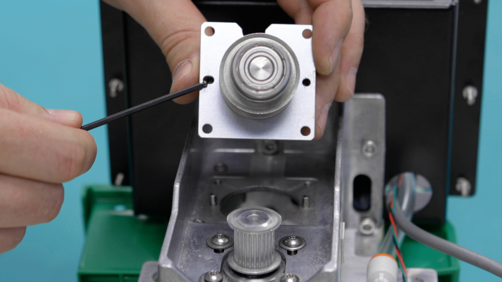
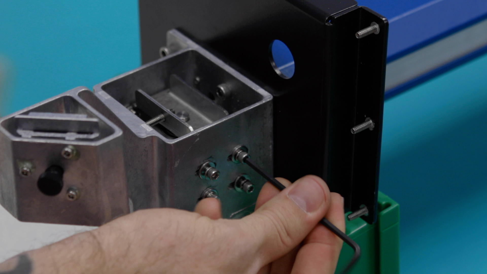
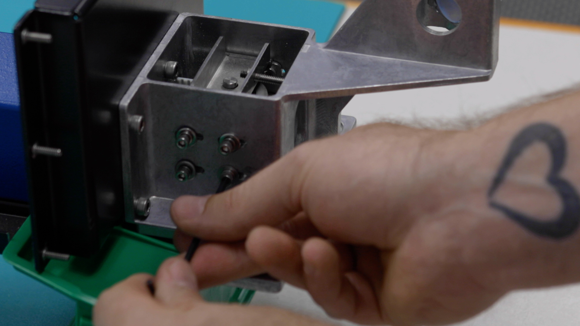
Using a 7/64” Allen Key, remove the four screws that secure the x-axis reducer assembly in place.
At the left side of the engraver, loosen the four 7/64” idler mounting screws located on the front side of the x-axis assembly, and the four idler mounting screws at the rear of the x-axis assembly.
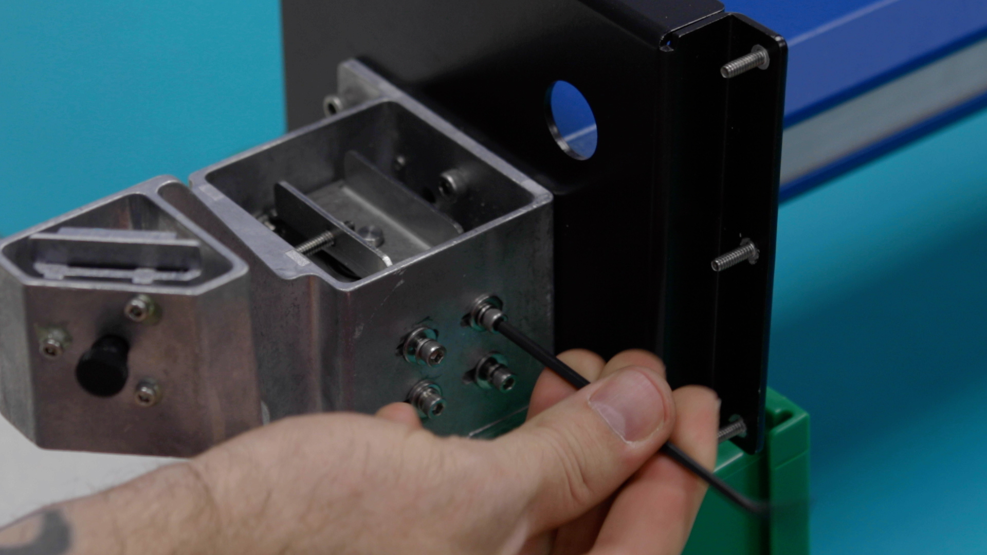
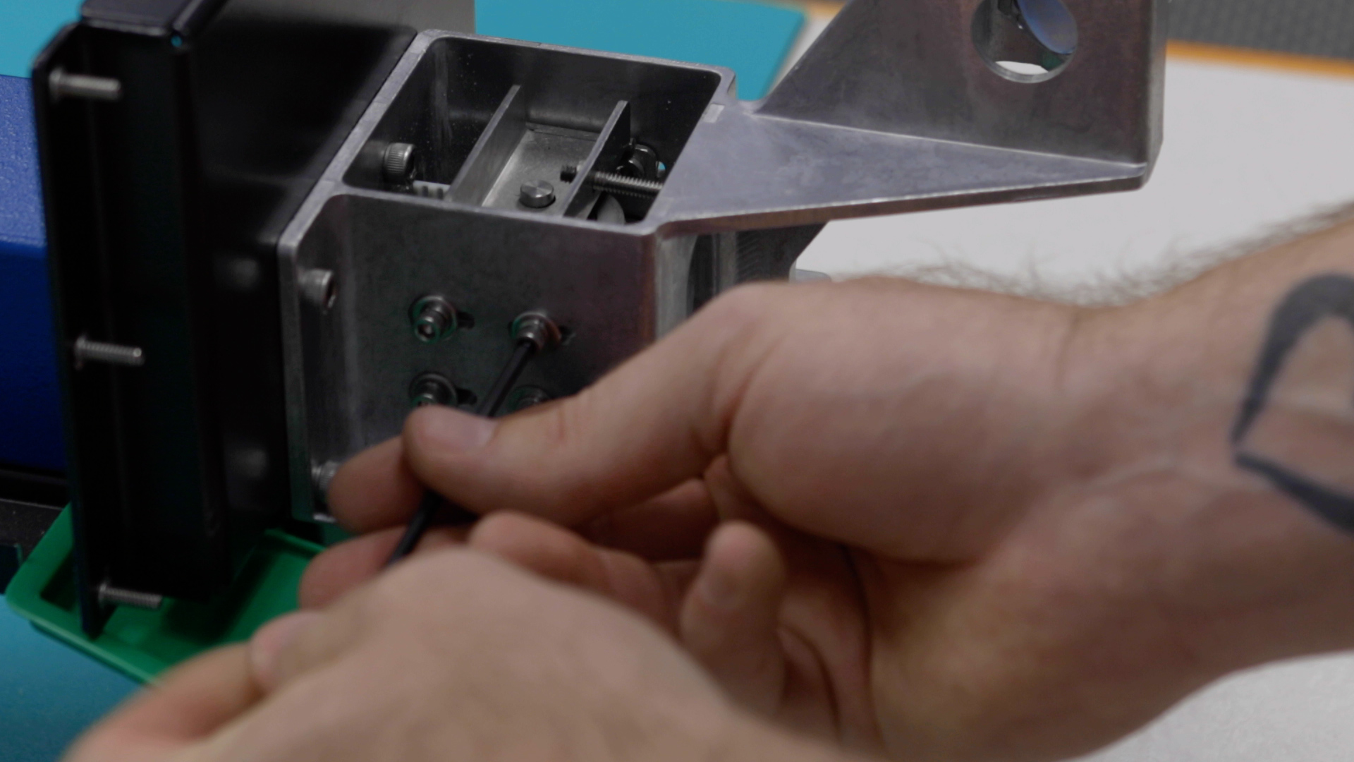
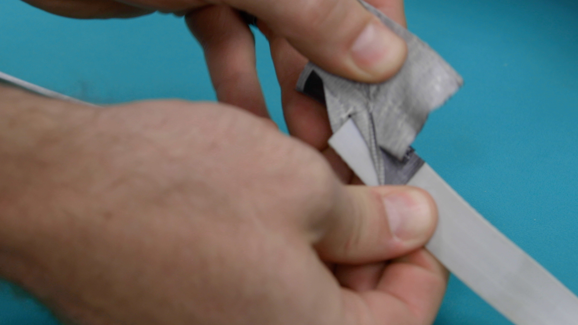
Remove the tension from the x-axis belt by loosening the two 7/64” screws on the idler assembly body.
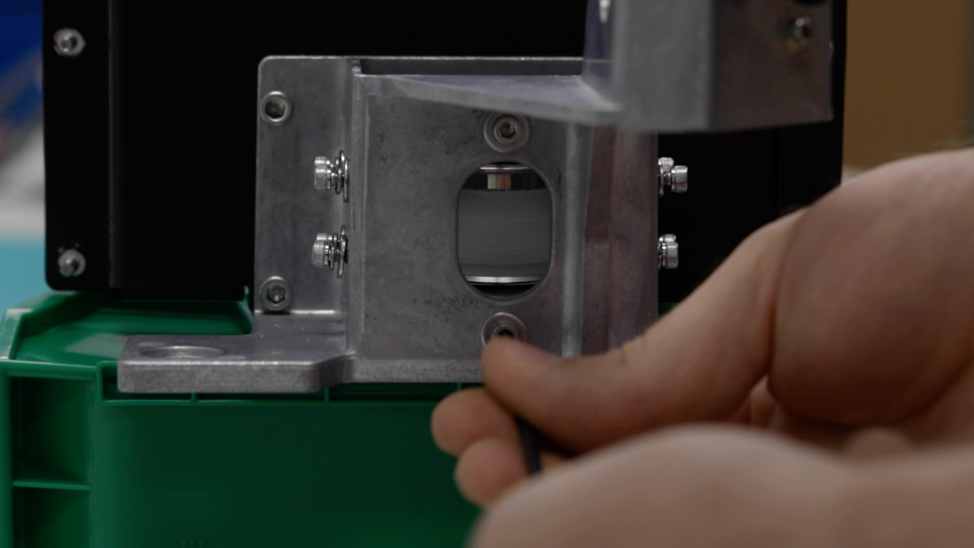
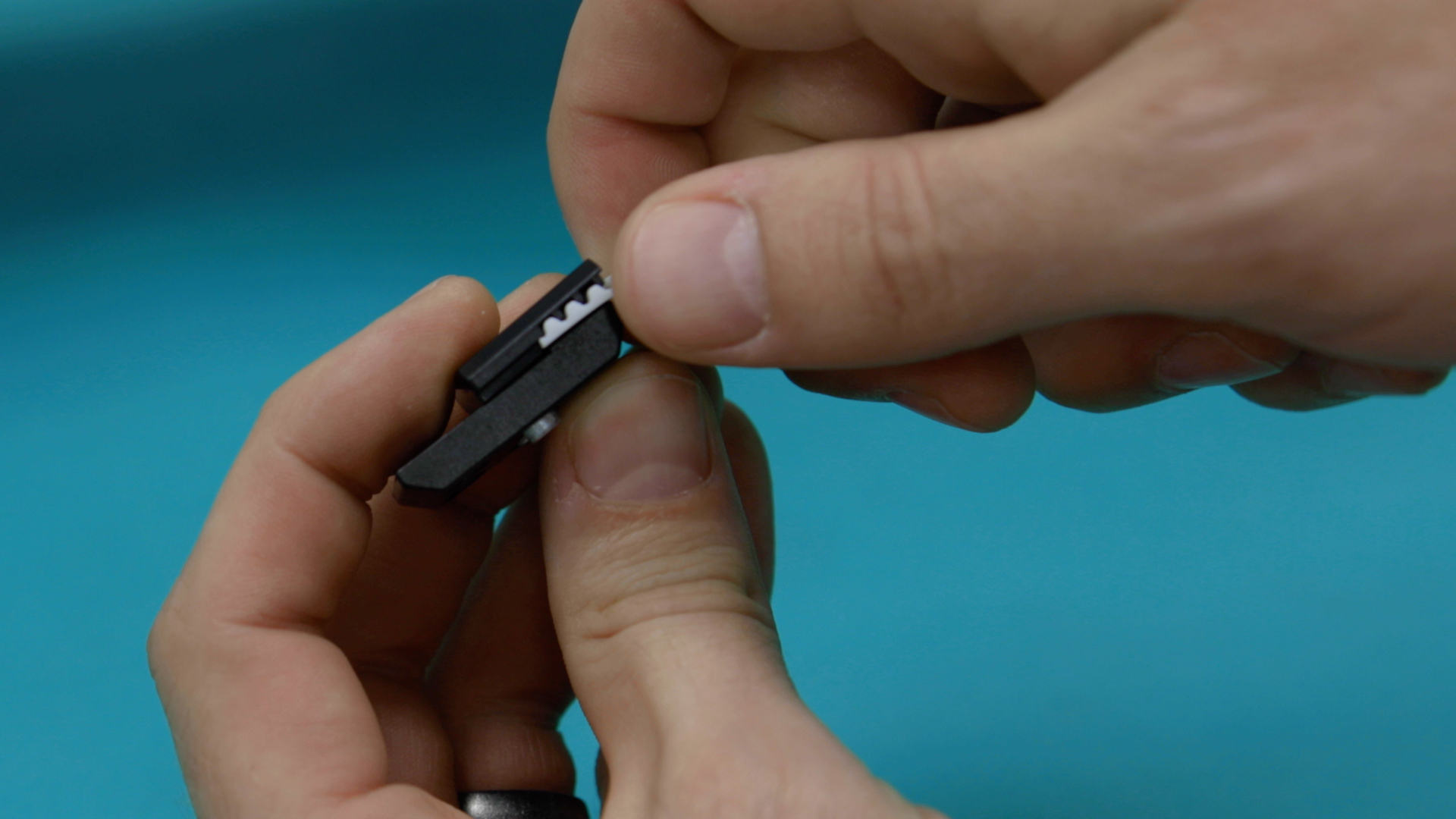
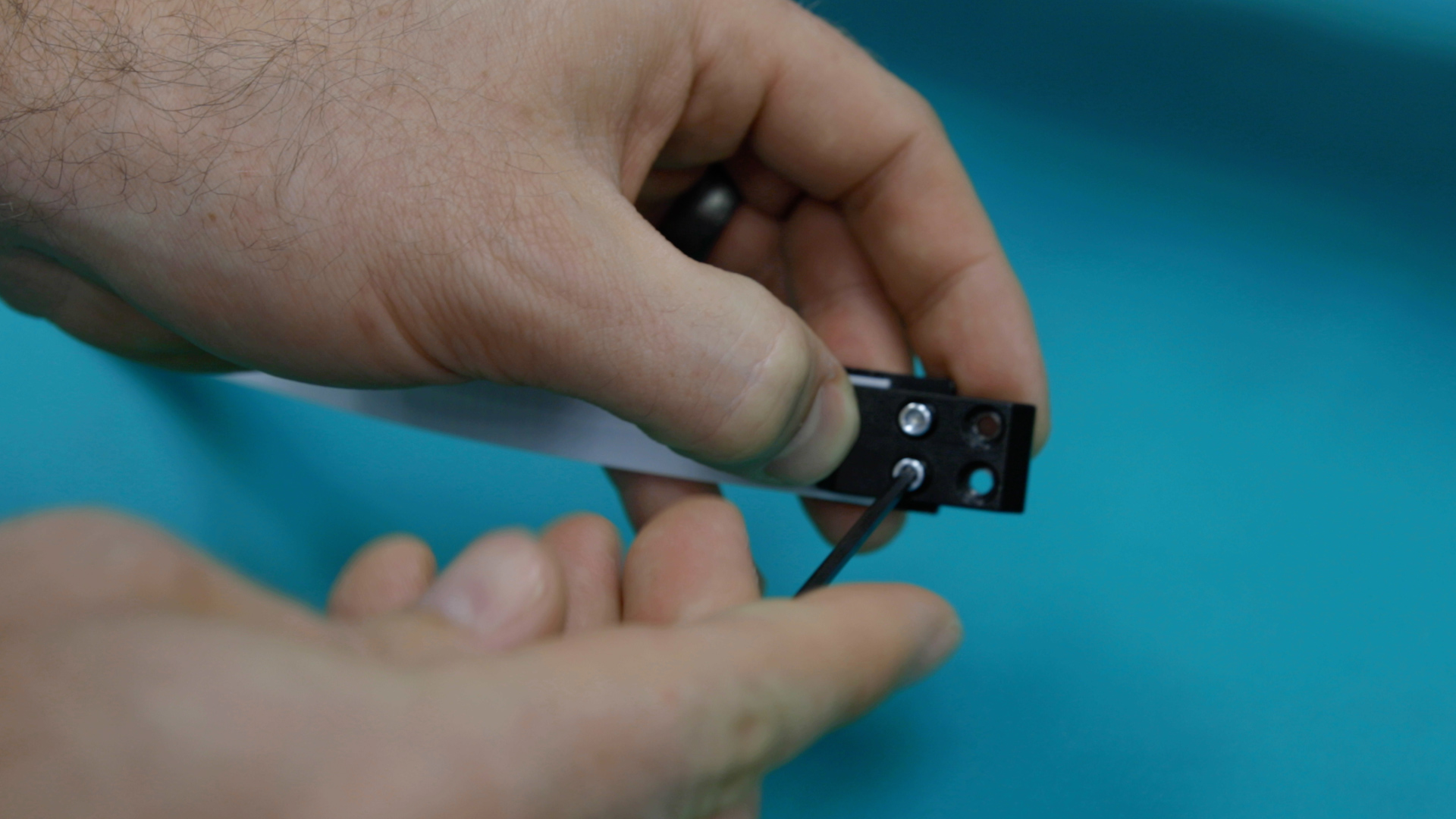
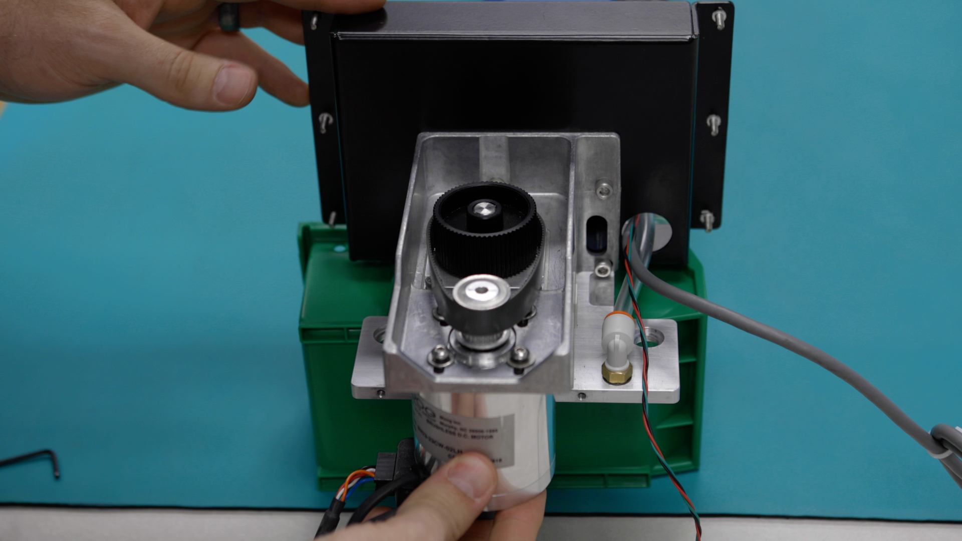
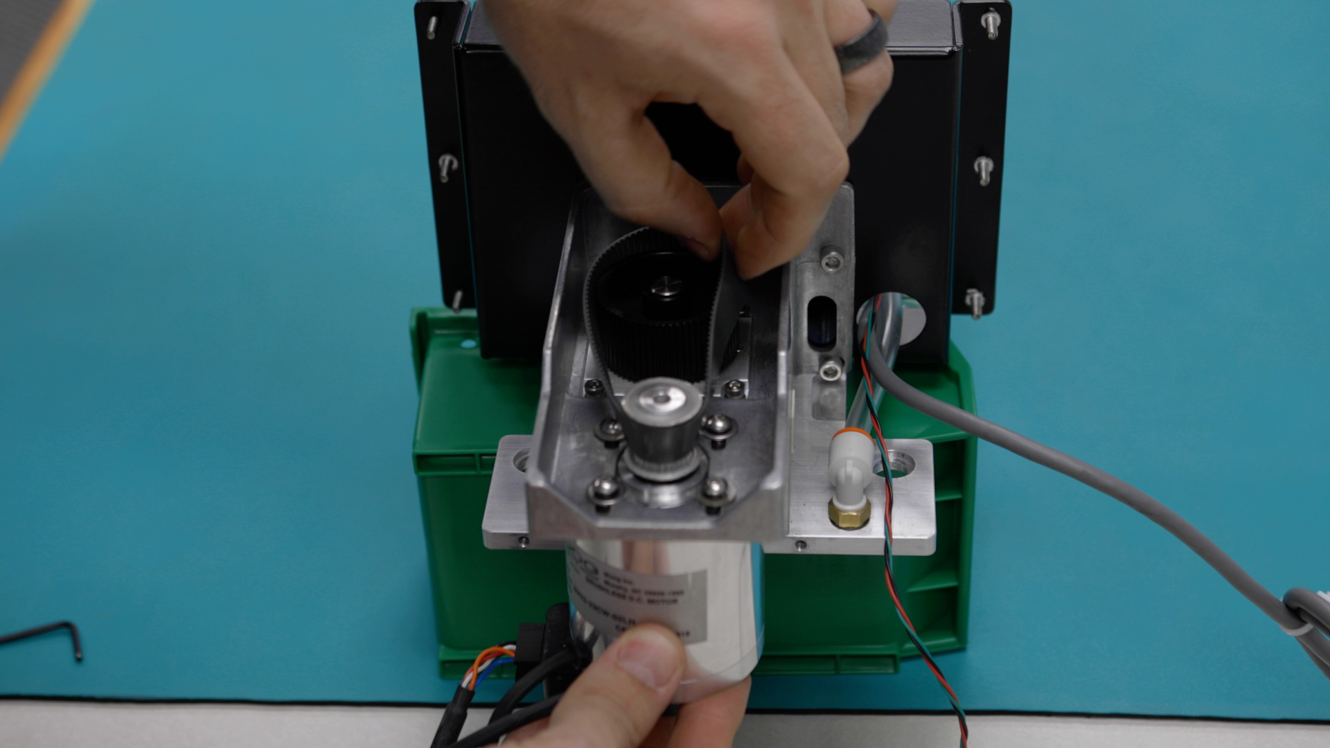
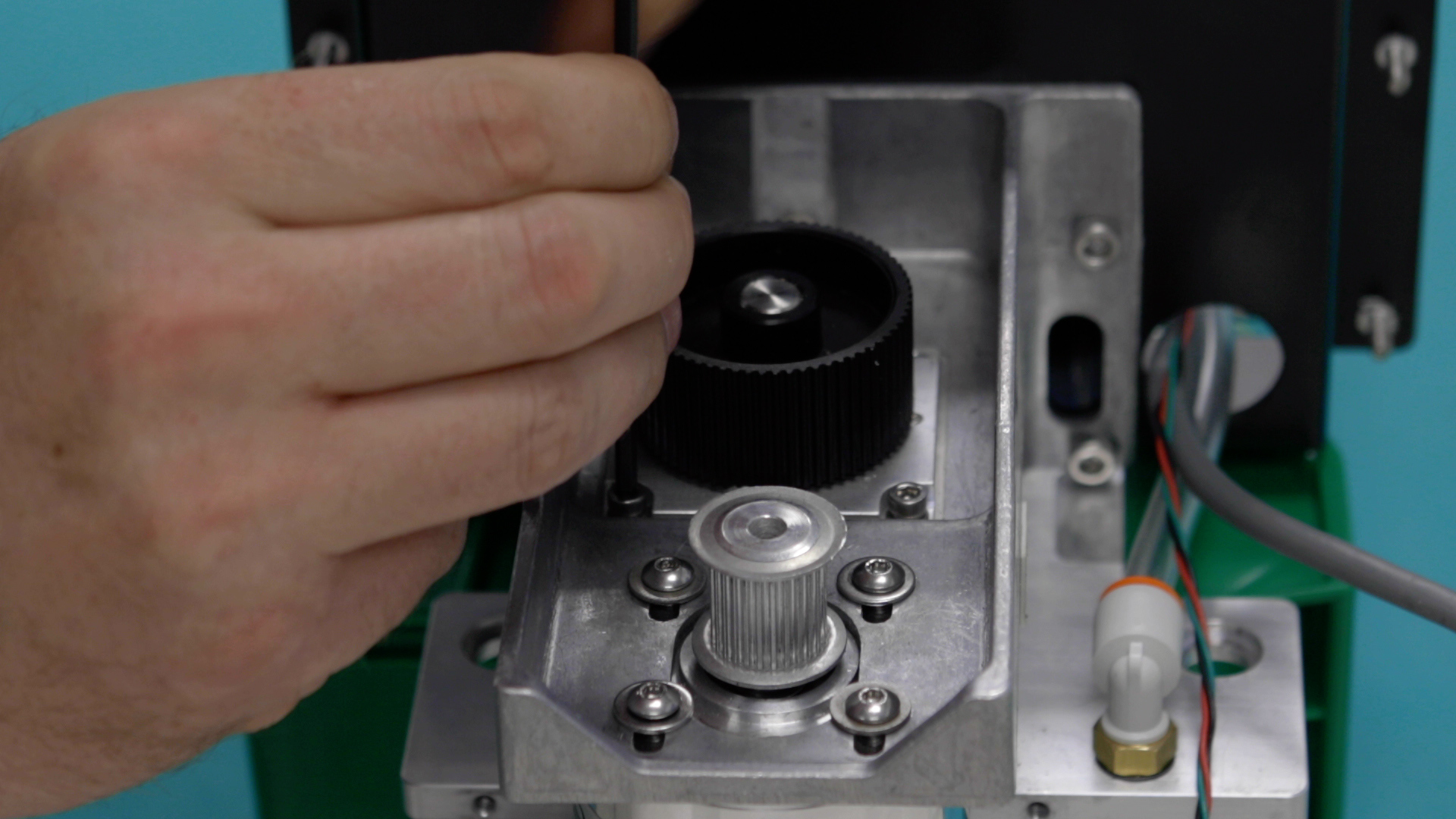
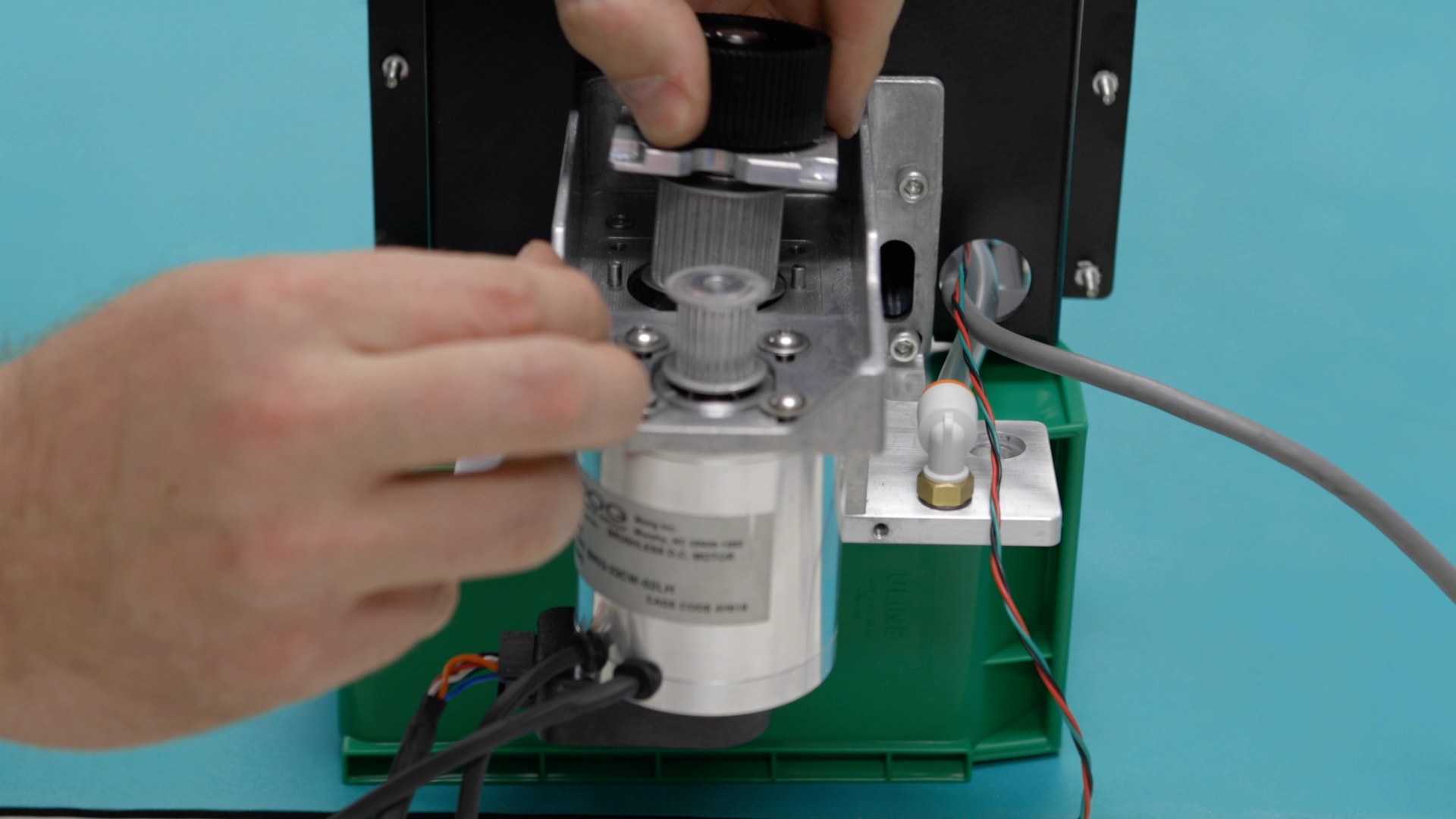
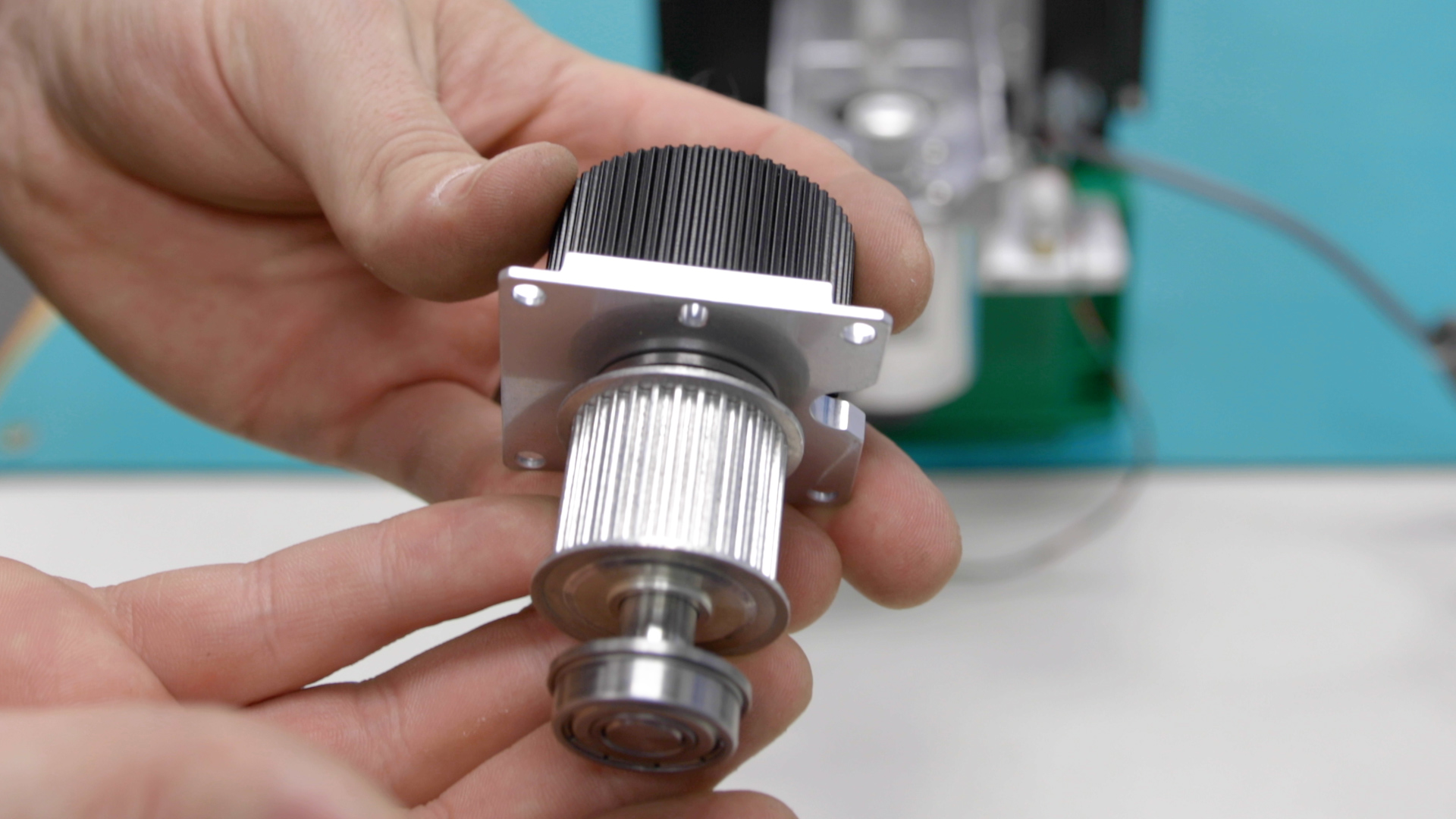
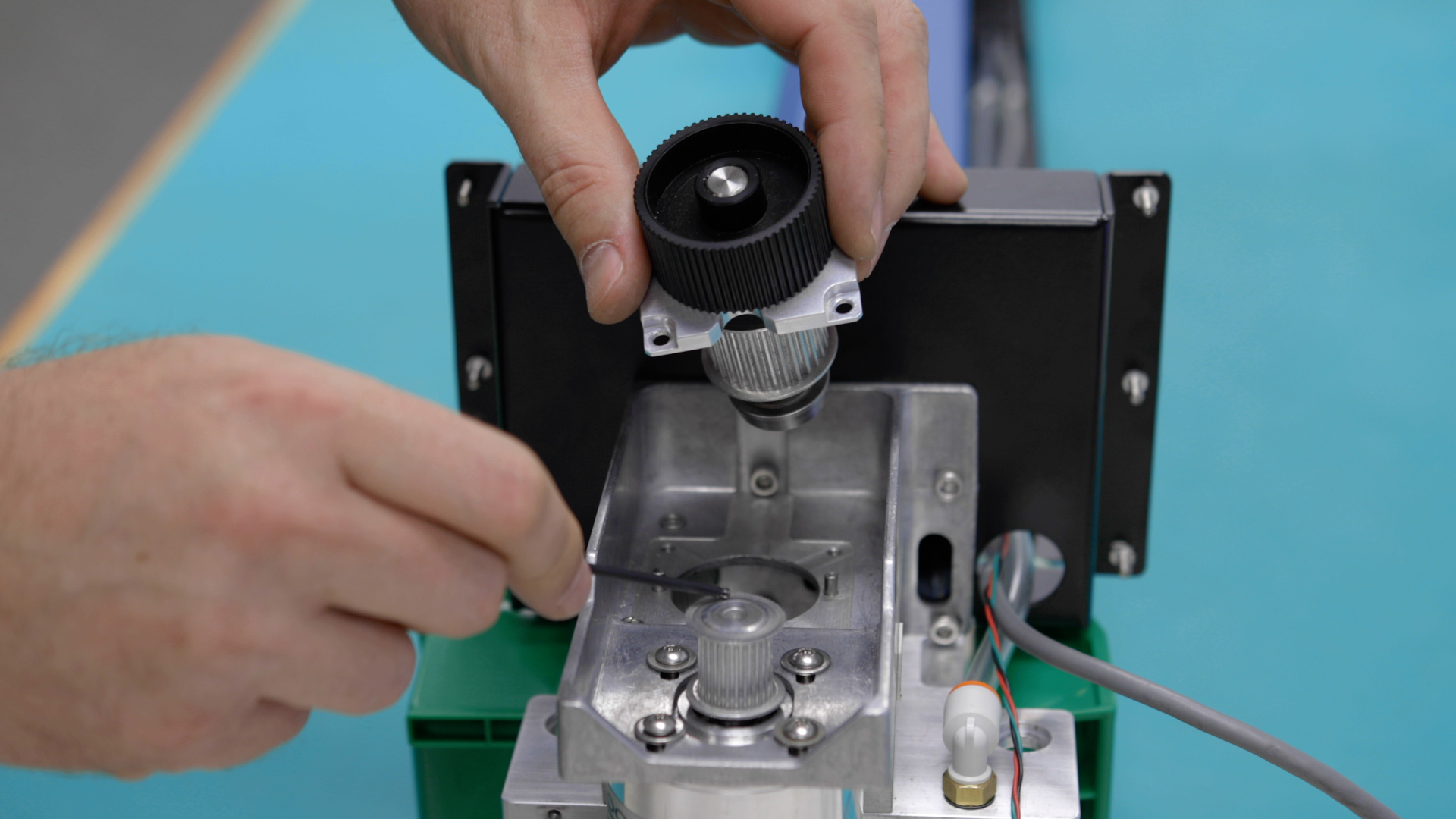
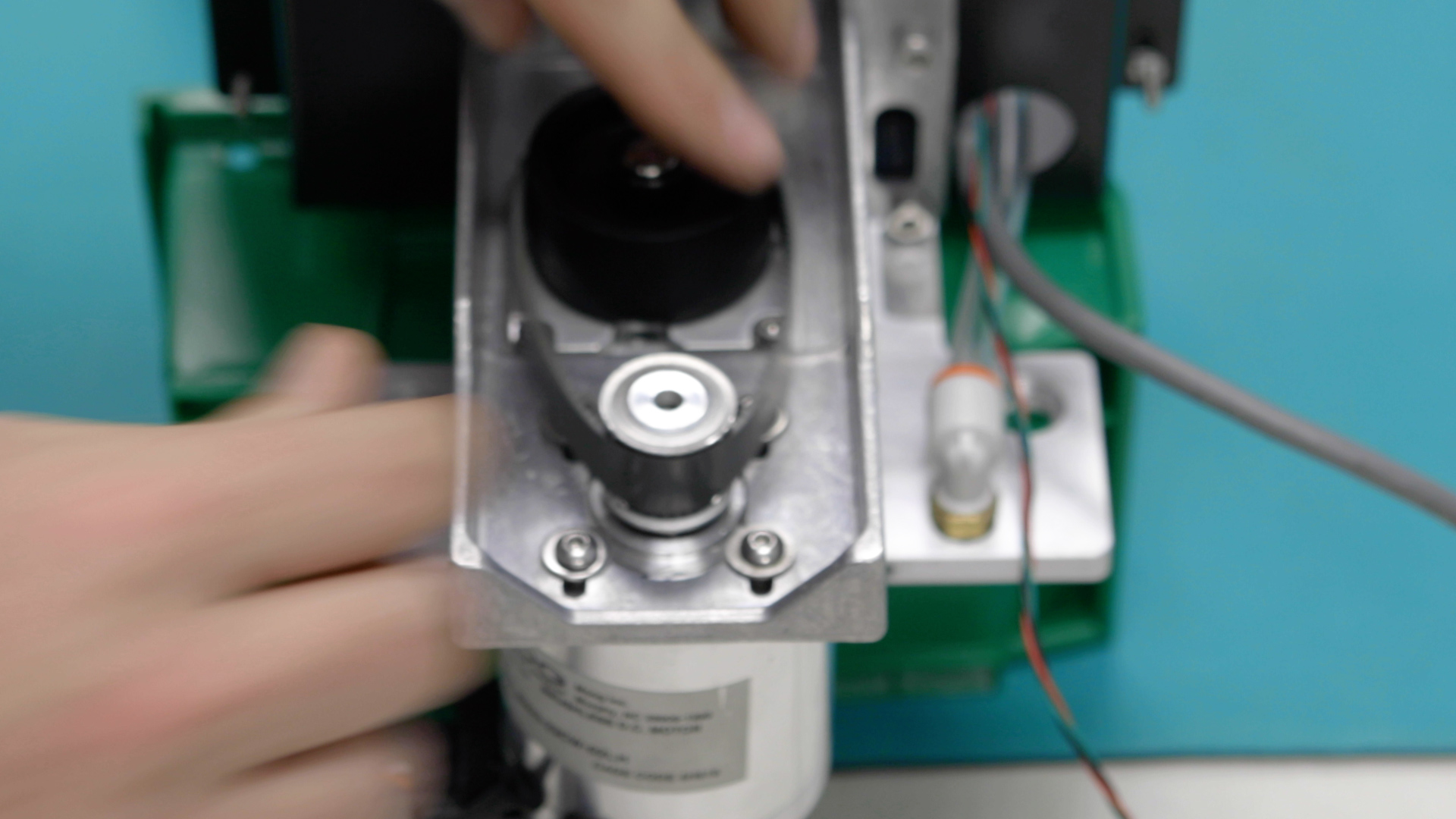
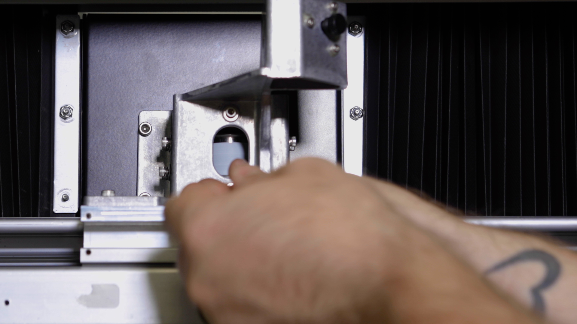
Remove the x-axis reducer from the reducer/motor housing.
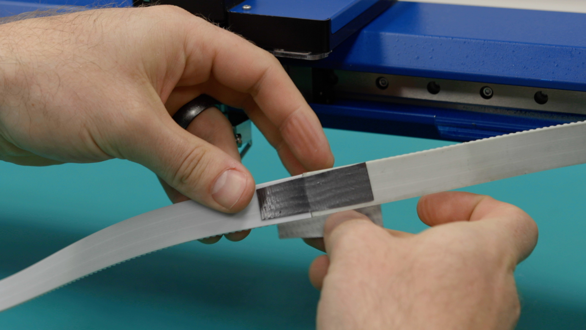
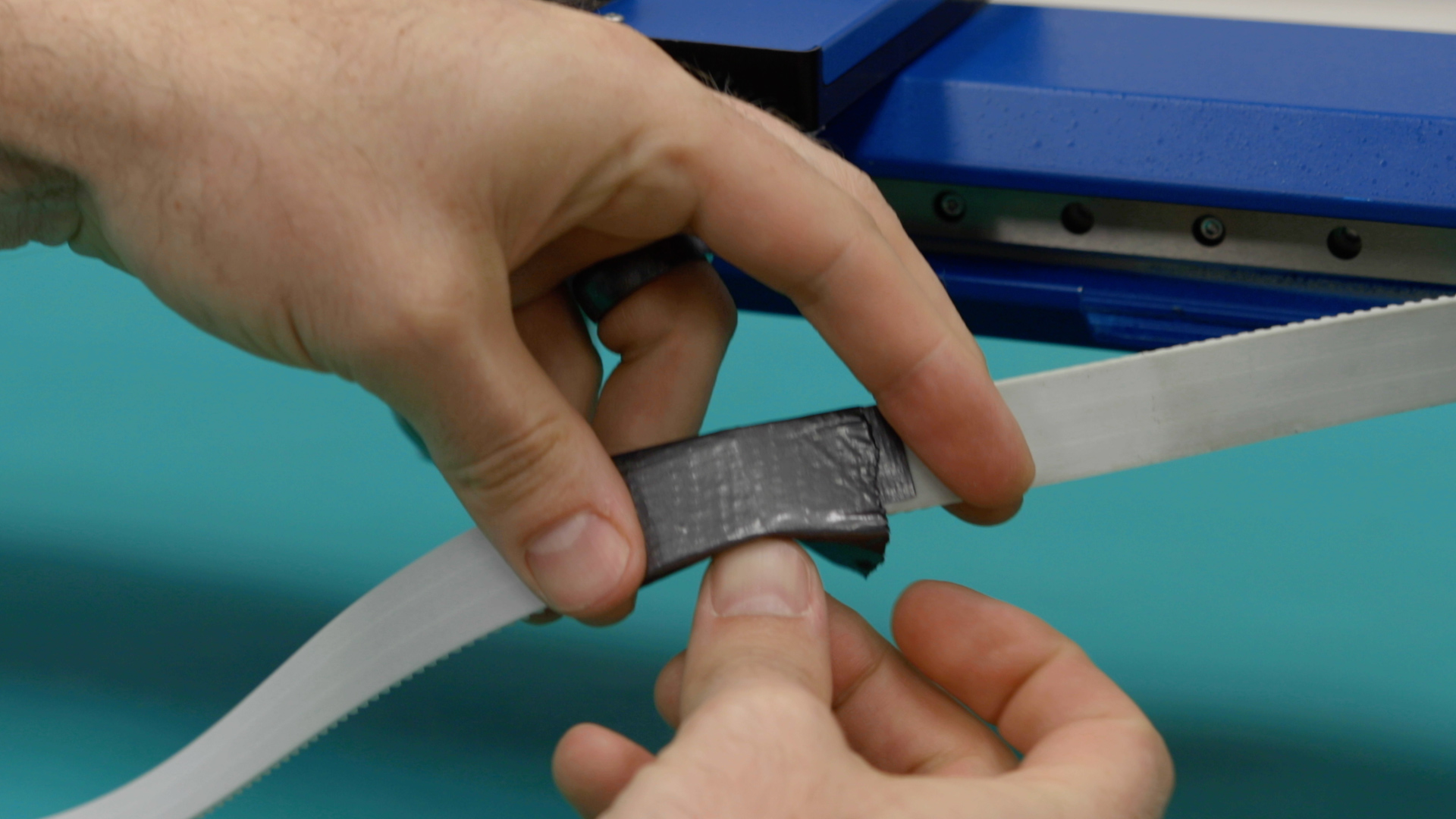
Pull the x-axis belt away from the center of the x-axis assembly.
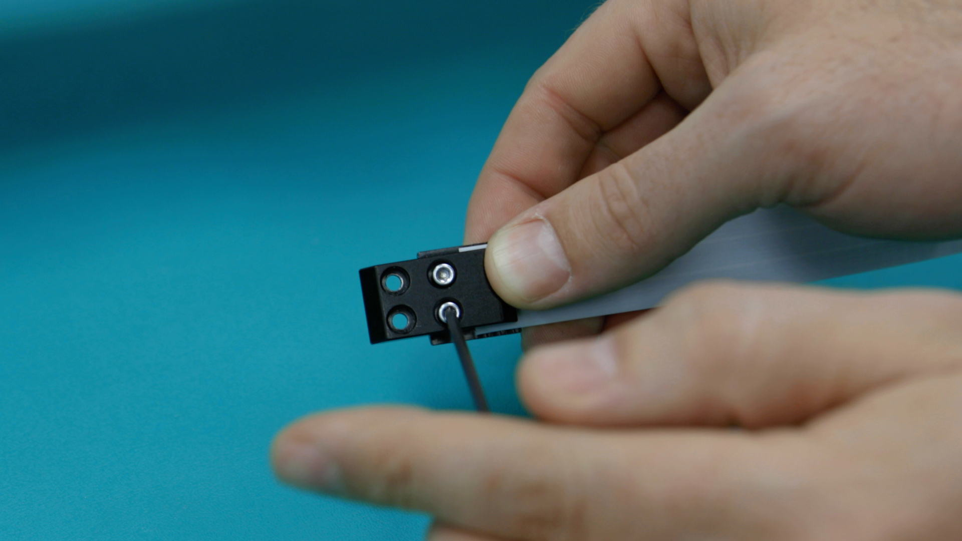
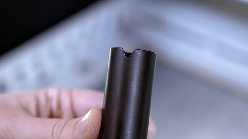
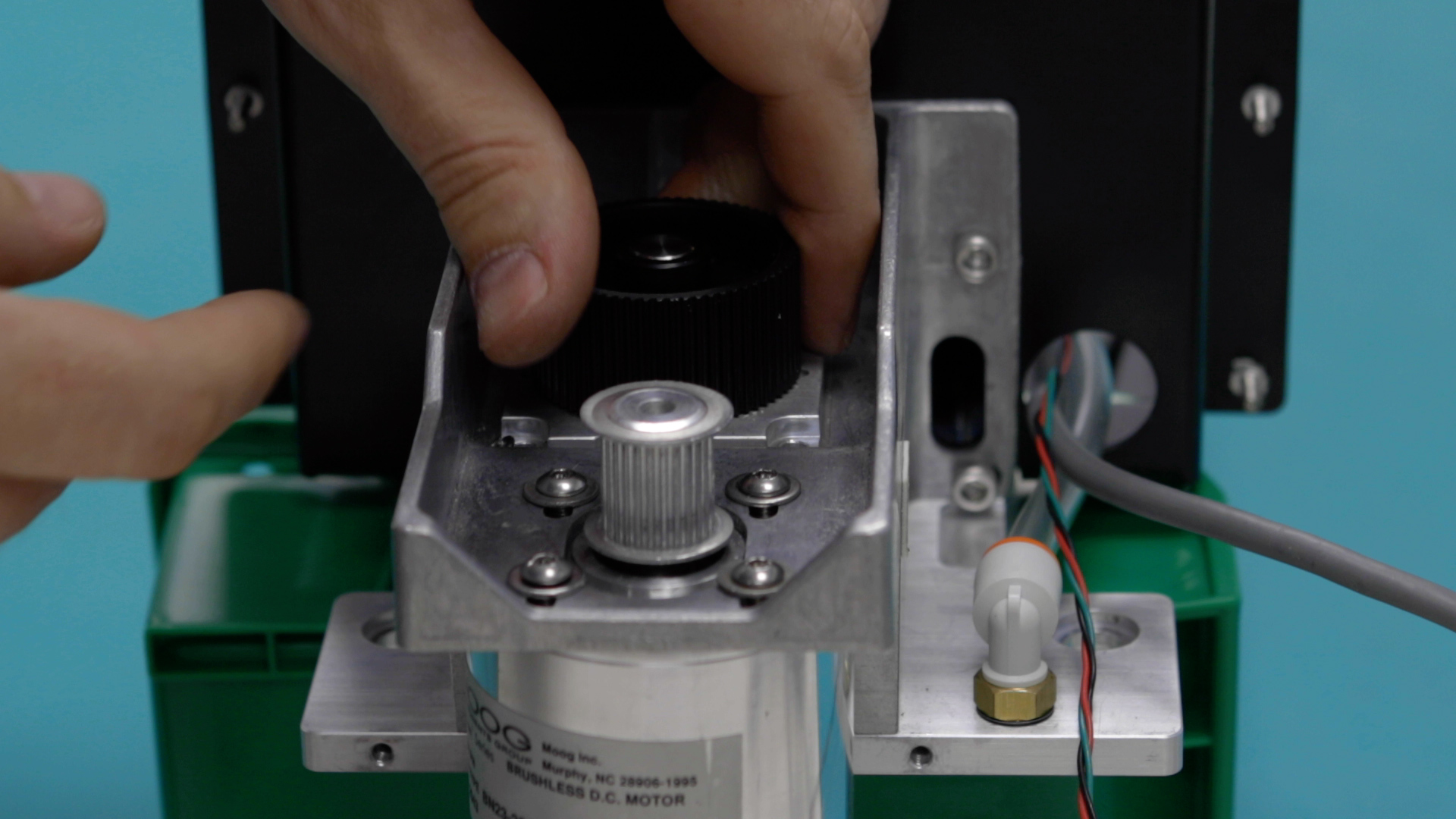
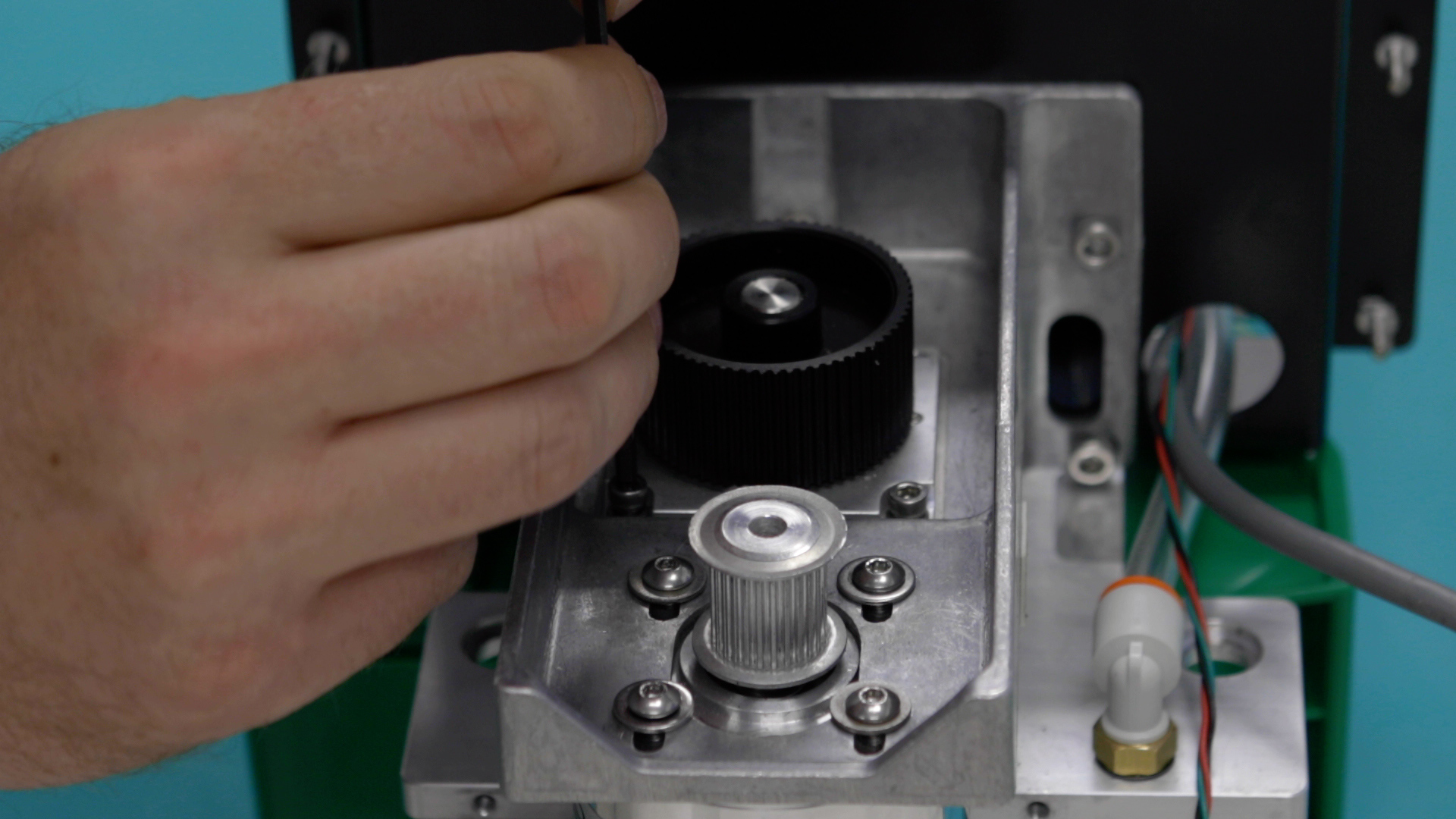
Place the reducer assembly in the reducer/motor housing. Ensure that the notch on the reducer baseplate is pointing towards the x-axis motor.
Install the x-axis reducer assembly and the four 7/64” Allen screws that secure it to the x-axis assembly.
Install the X-Axis Reducer Belt
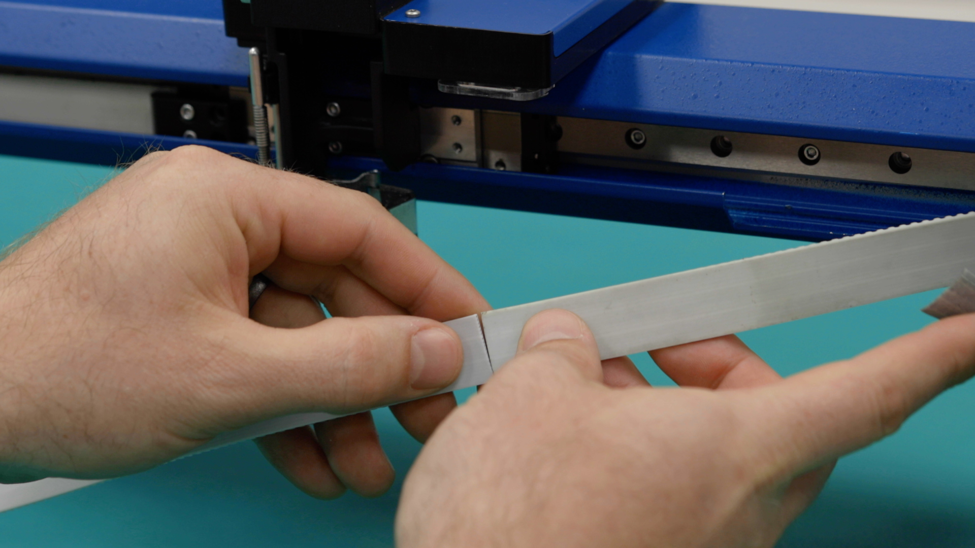
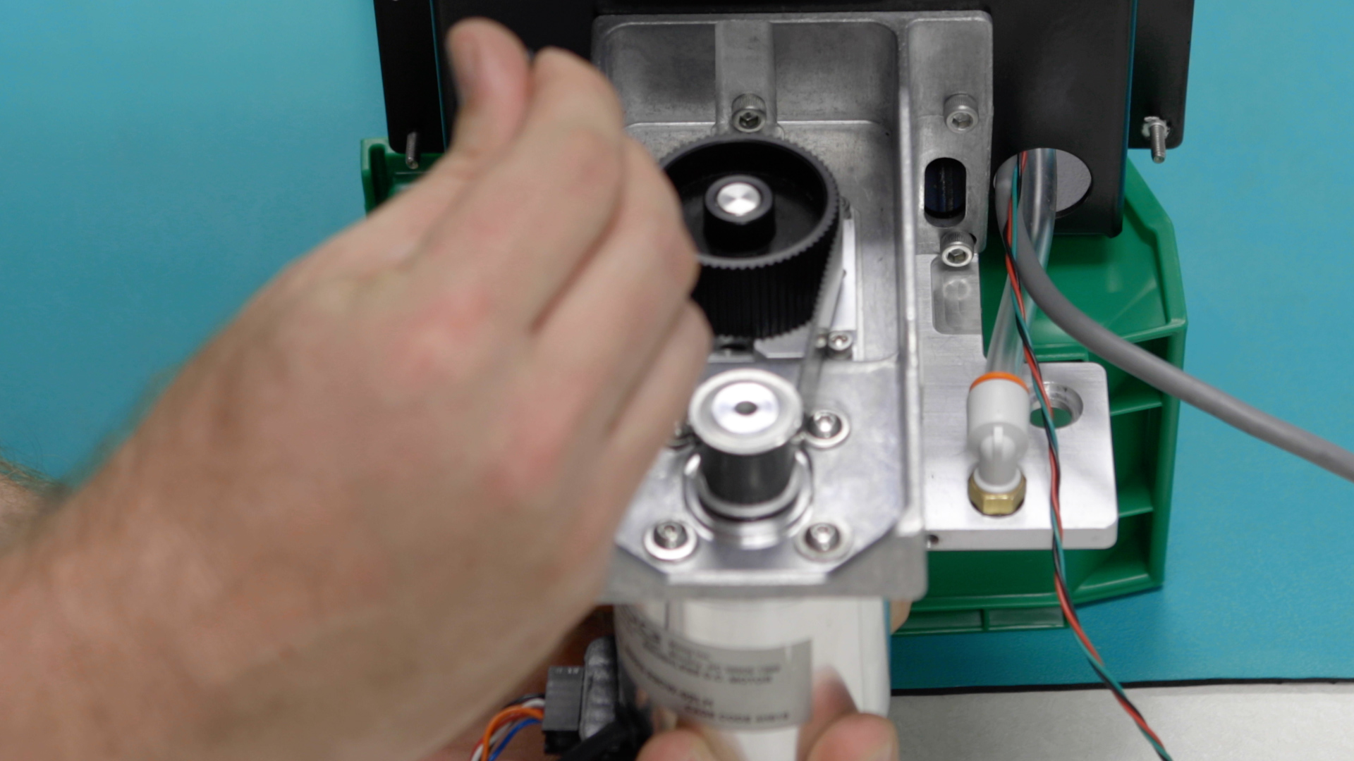
Using your hands, manually apply tension to the reducer drive belt by pulling the x-axis motor away from the reducer.
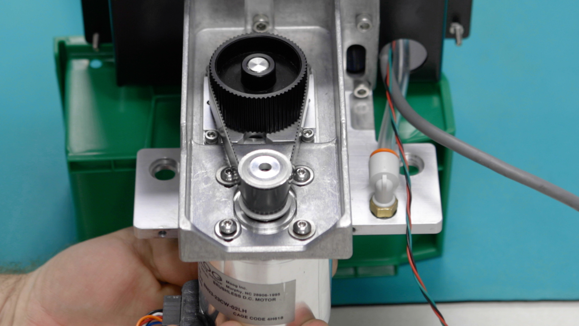
Once the slack has been removed from the reducer belt, tighten the four 2.5 mm x-axis motor mounting screws.
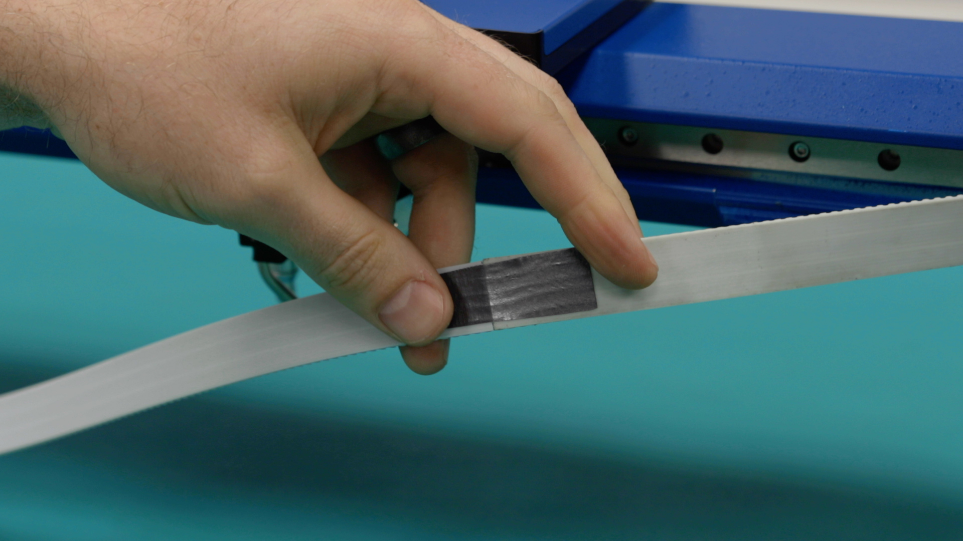
Now it’s time to tension the x-axis belt, begin to apply tension to the belt by tightening the two 7/64 belt tensioning screws that were loosened earlier, until there is no slack left on the belt.
Now you may re-install the X-axis Assembly.
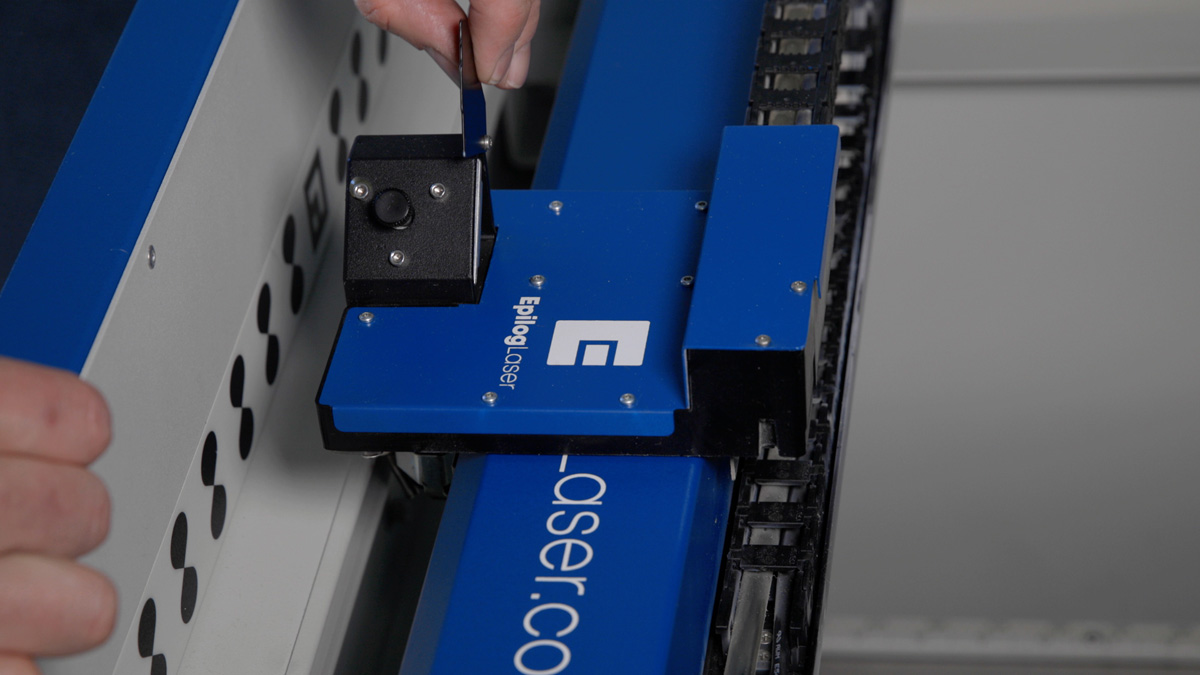
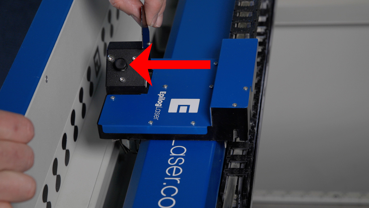
Insert the x-axis assembly through the right side of the engraver, taking care to clear the carriage assembly through the opening without damage.
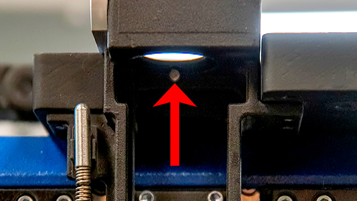
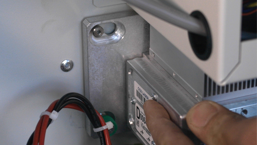
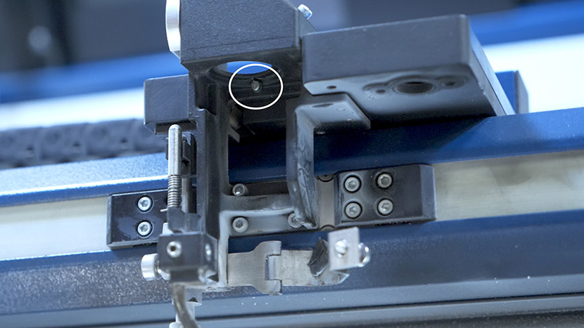
Once fully inserted, place the x-axis assembly onto the y-axis bearing blocks. On the y-axis bearing blocks is a locating pin that ensures the correct placement on the x-axis assembly. These pins fit into an opening on both the left and right side of the x-axis assembly.
Install and/or tighten the four 5/32” fasteners that secure the x-axis assembly to the y-axis bearings. There are two on the right side and two on the left side.


Put on the anti-static wrist strap, clipping the strap to any metal part of the machine.
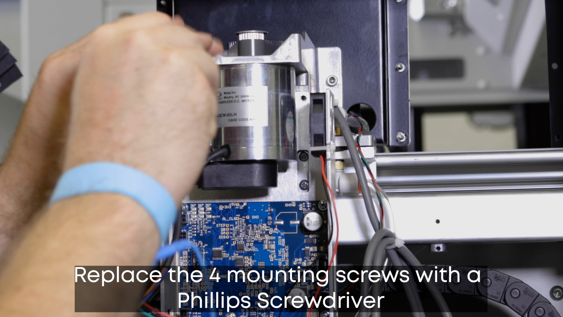
Replace the 4 mounting screws supporting the drive board with a Phillips Screwdriver.
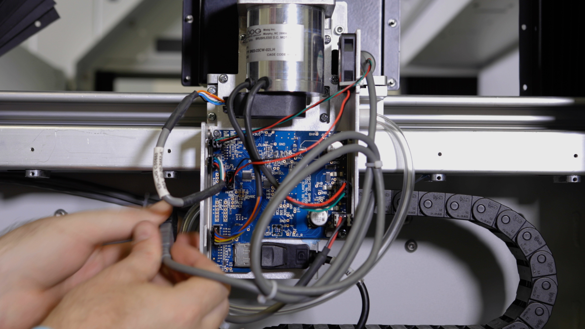
Reconnect the seven (7) electrical connectors from the drive board. The electrical connectors on the drive board are all unique and as such, will only fit into one receptacle.
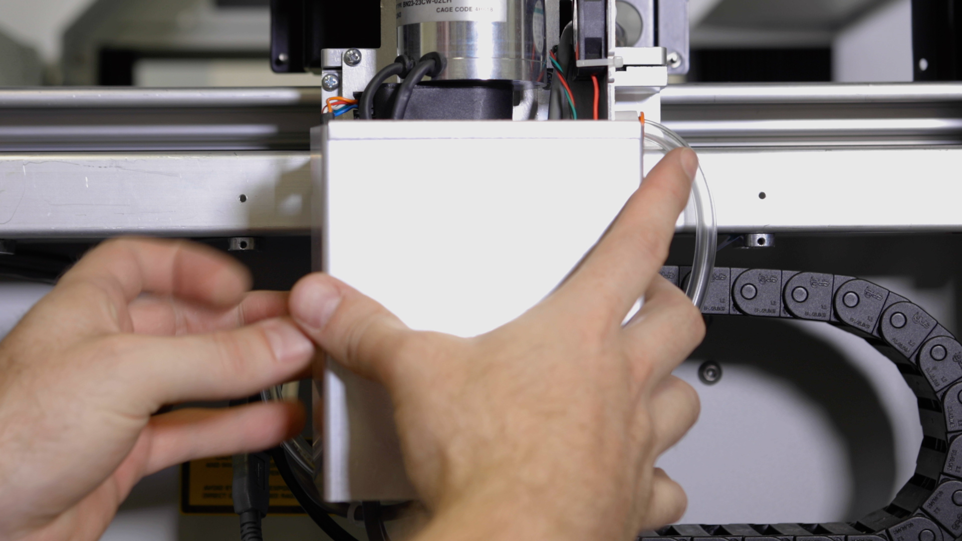
Replace the x-axis motor drive board cover and tighten the 4 screws securing it.
Reconnect the left and right bellows on both sides of the machine and tighten the six 5/16” nuts which secure them in place.
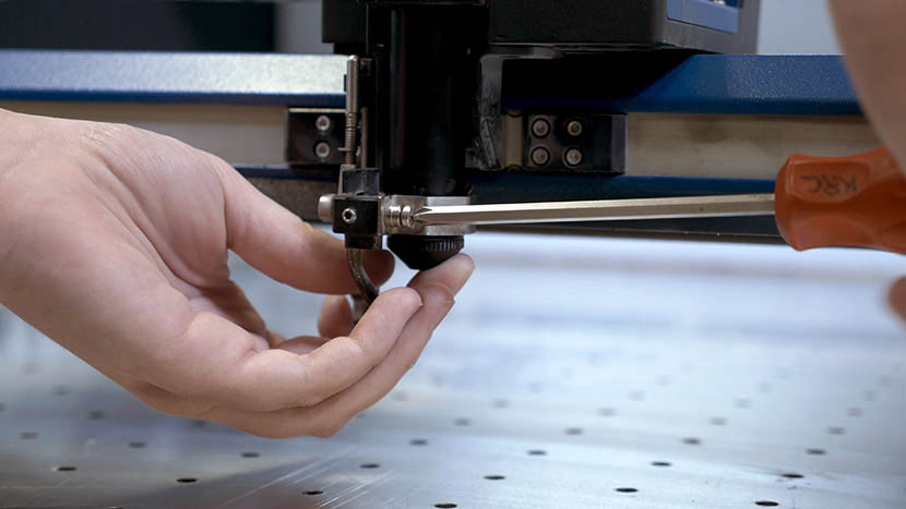
Install the lens tube by tightening the Phillips screw on the retaining collar which secures it, ensuring that it does not fall.
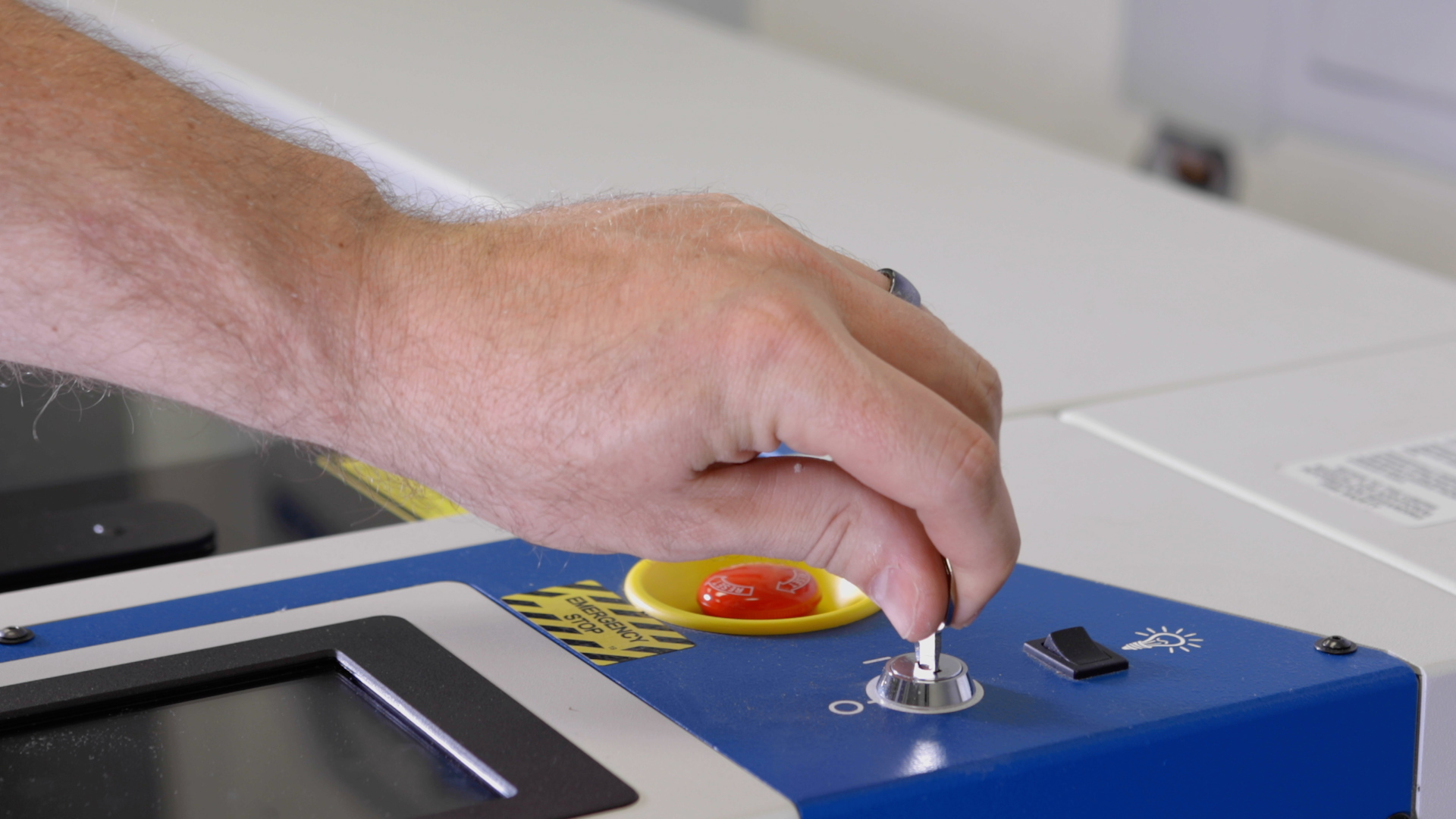
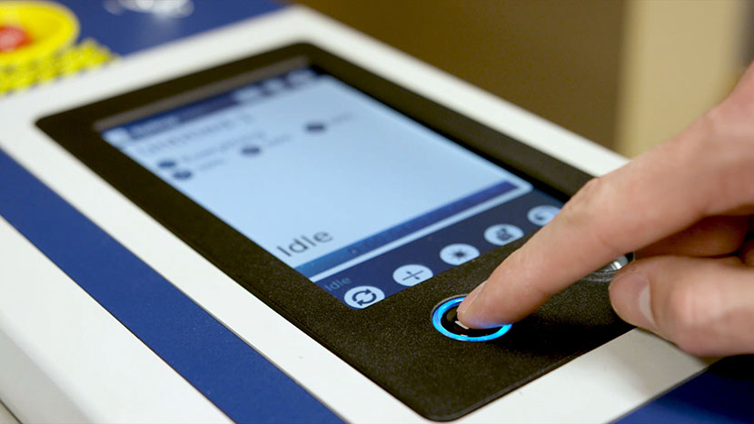
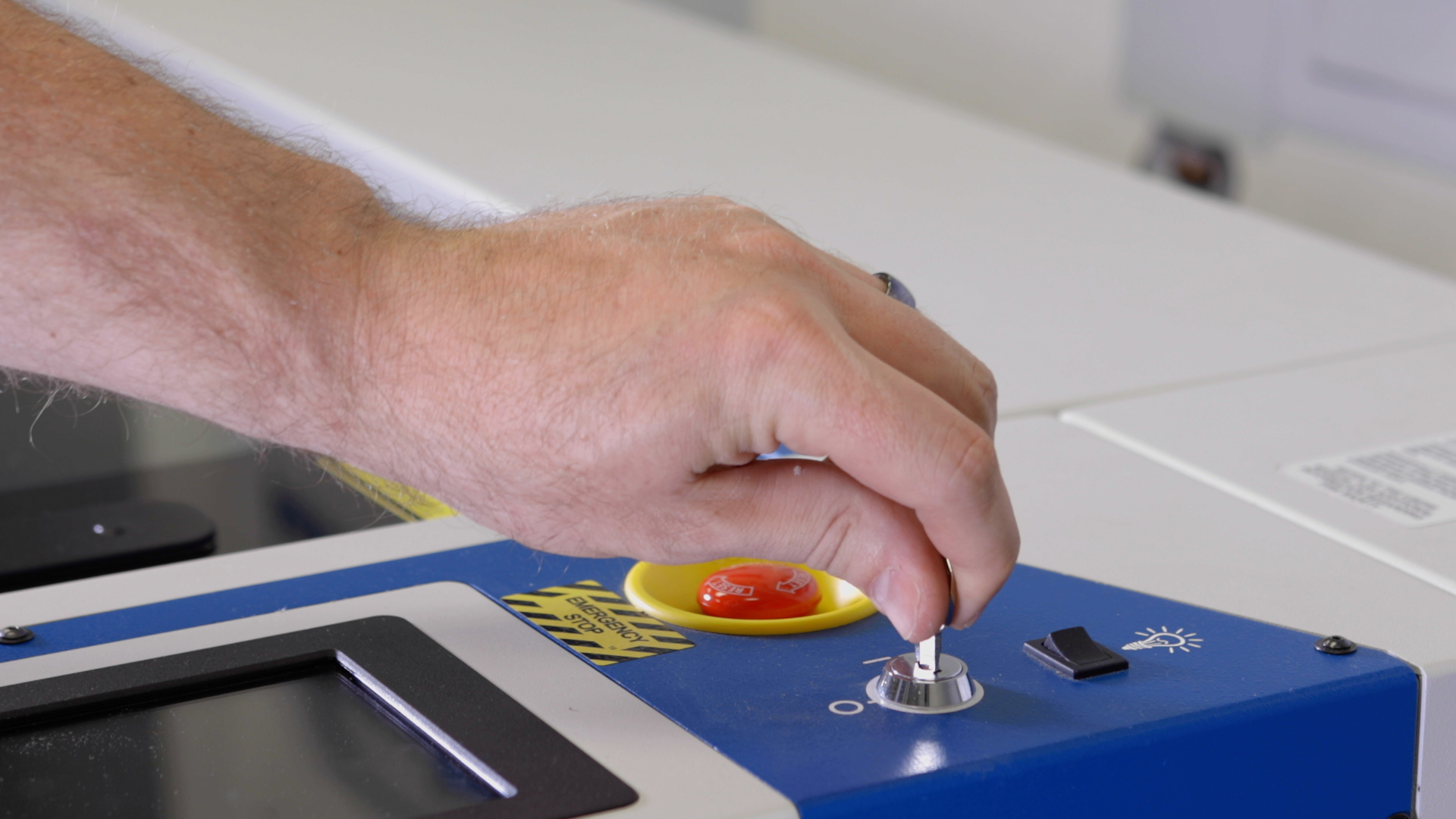
Plug in and power on the machine.
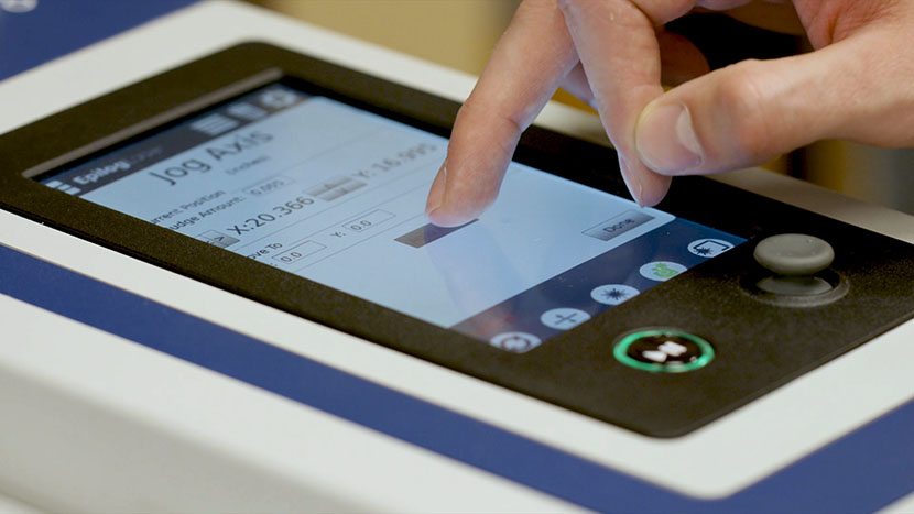
After installation of a new x-axis assembly, confirm the home position is accurate and recalibrate it if needed.
Plug in and power on the machine.
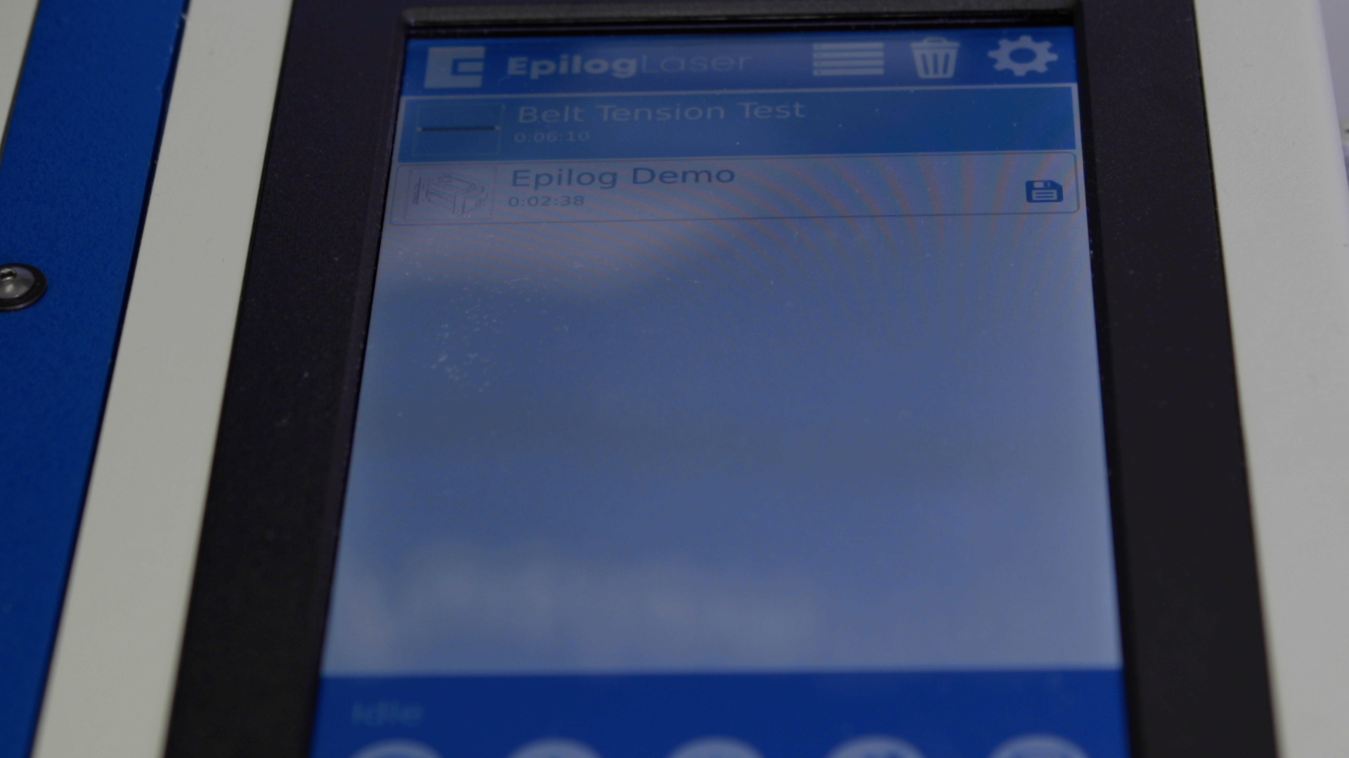
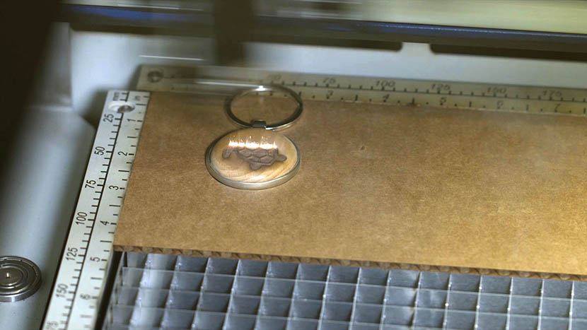
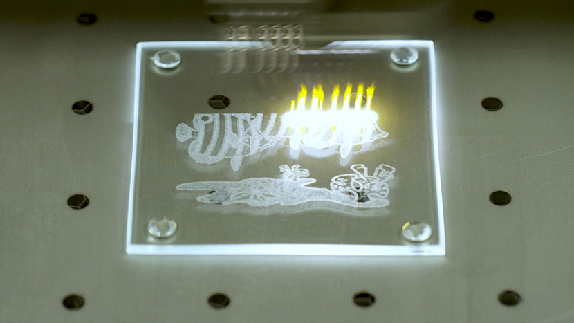
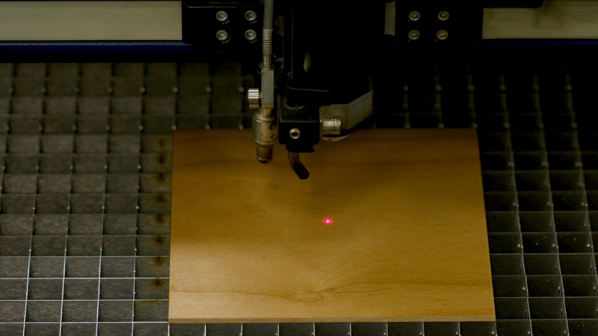
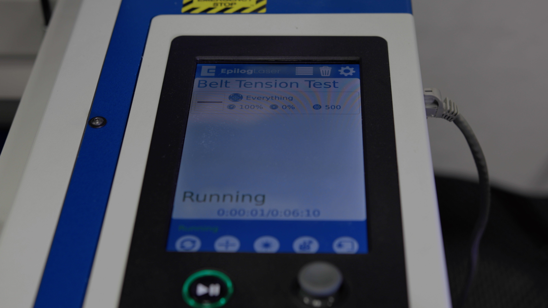
Once the slack is removed, you will need to run an engraving test.
Plug in and power on the machine.
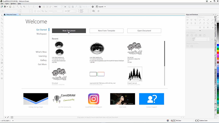
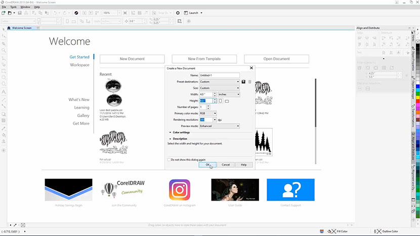
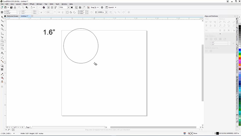
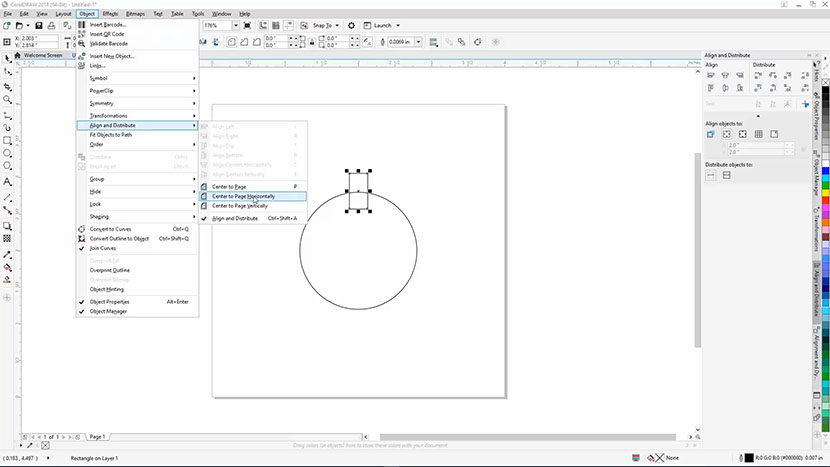
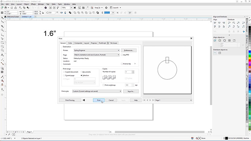
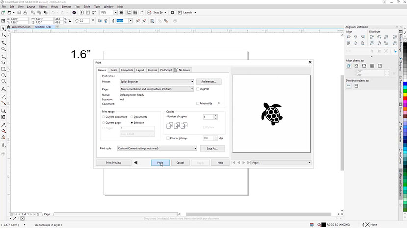
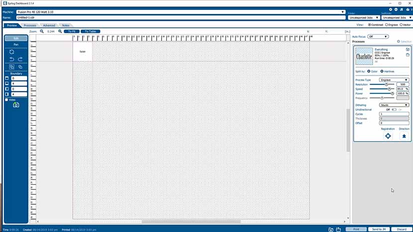
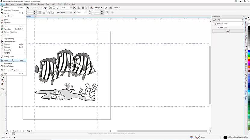
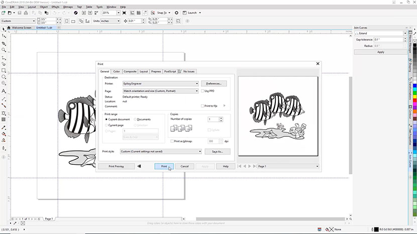
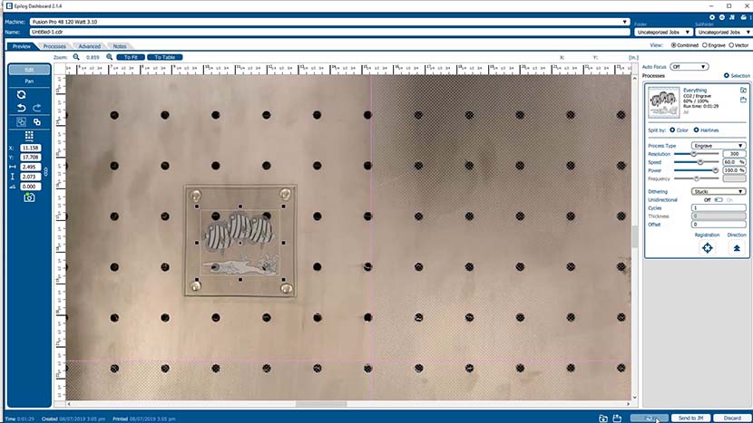
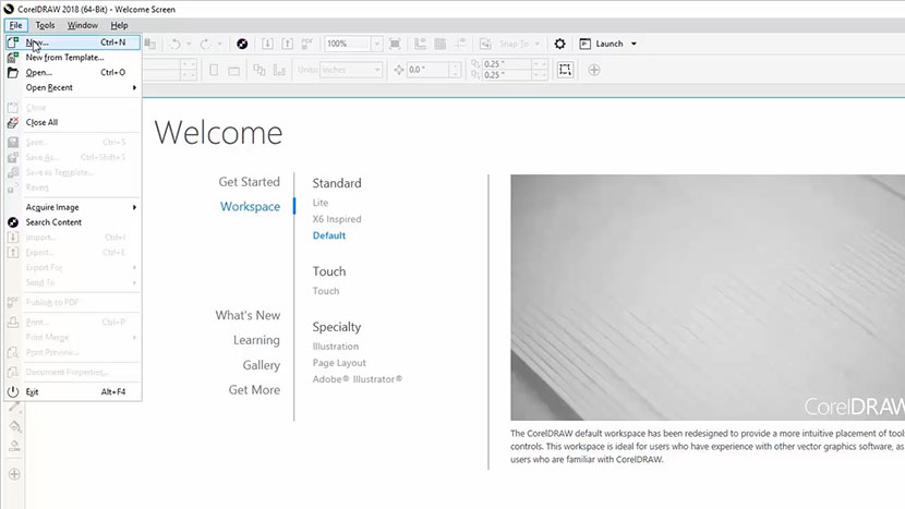
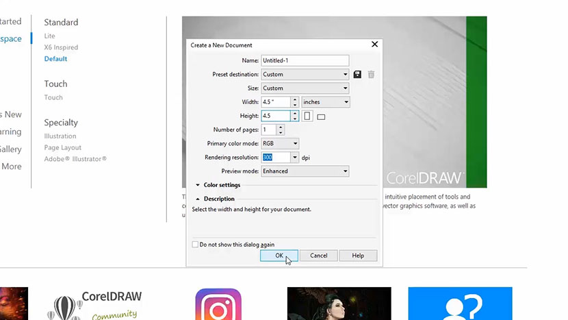
Open your preferred illustrating program and create a black raster box on an artboard that is:
- • For Pro 48: 46” or 1100mm wide
- • For Pro 32: 30” or 800mm wide
- • and Roughly 4” or 100mm tall
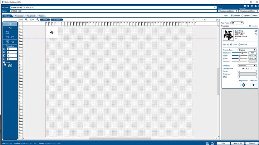
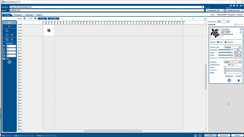
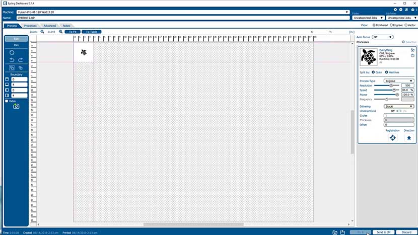
Set the speed to 100%. The power setting is unimportant, since we will be running the job with the machine lid open and the laser will not be firing.
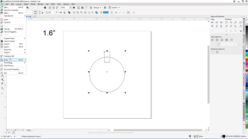
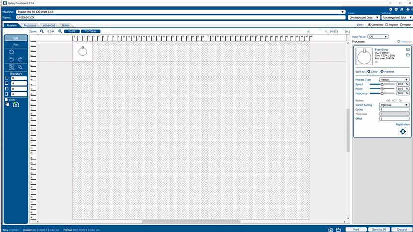
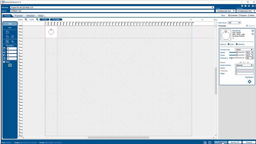
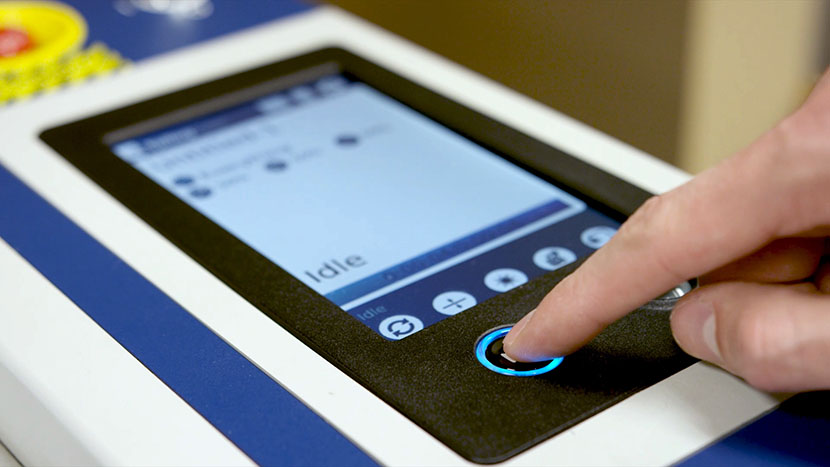
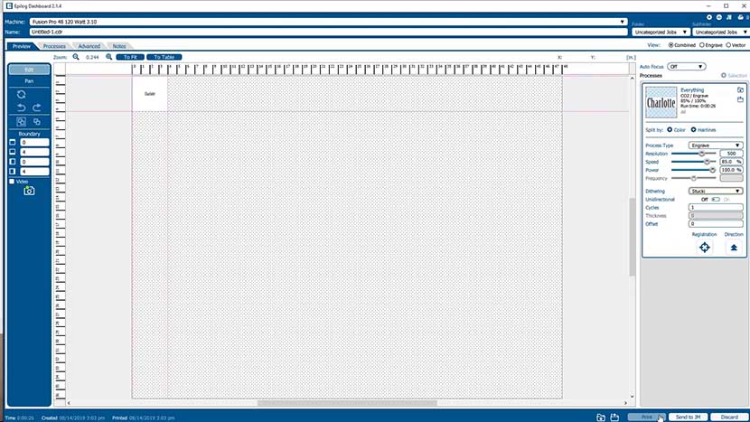
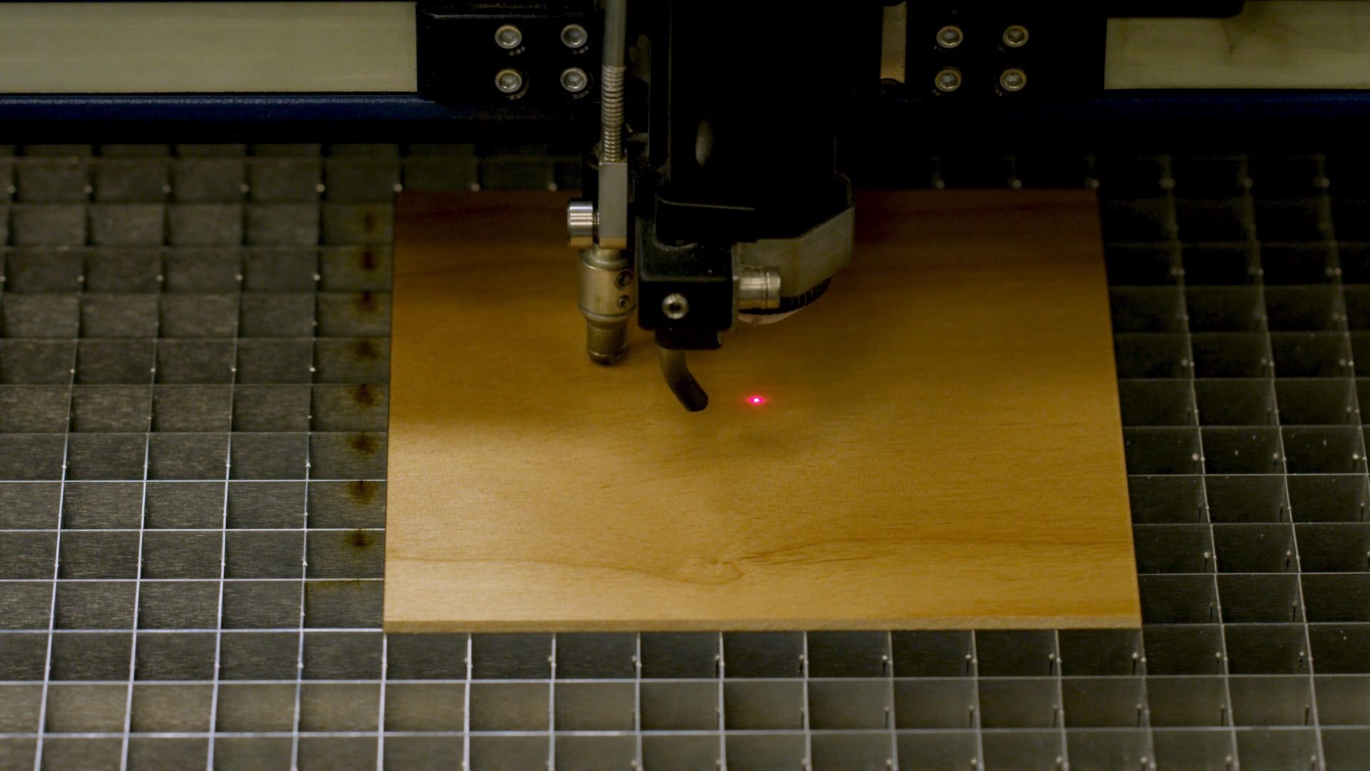
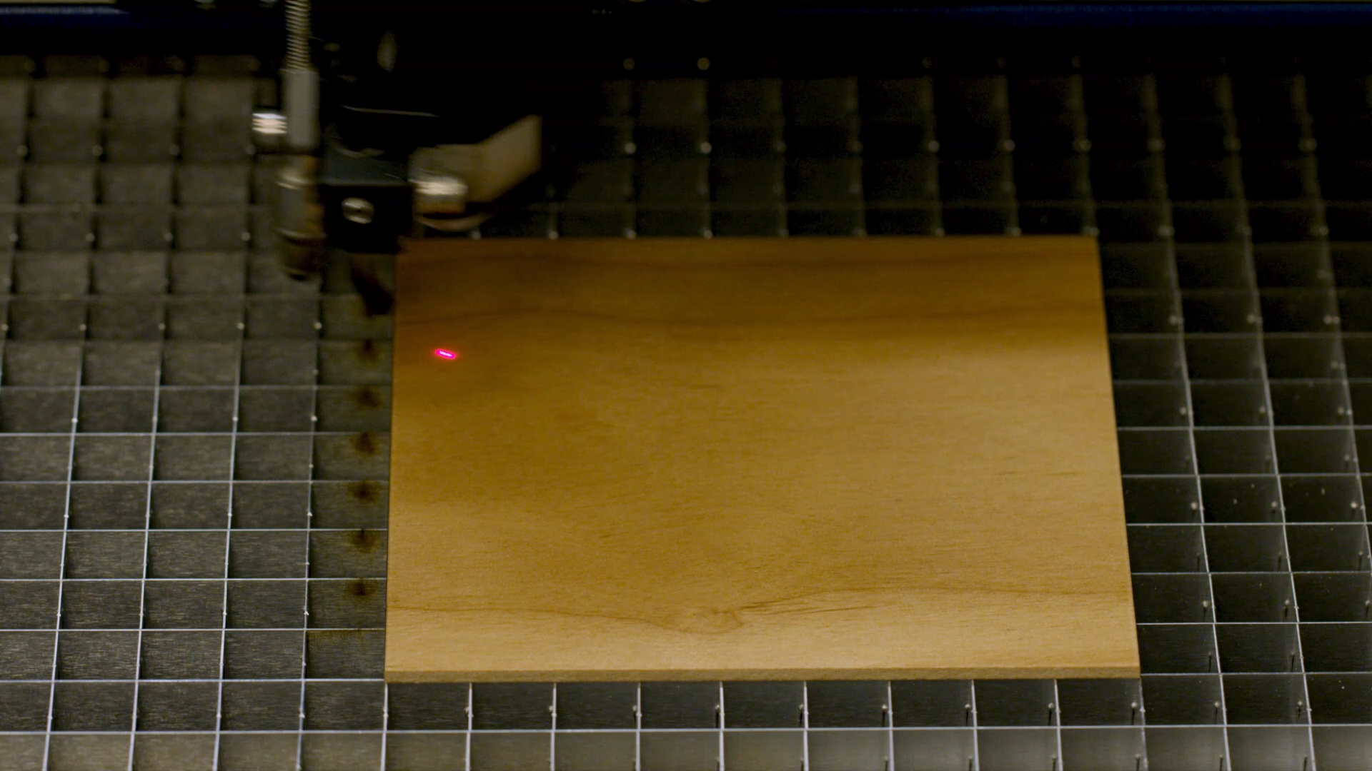
Send the job to the engraver and start the job.

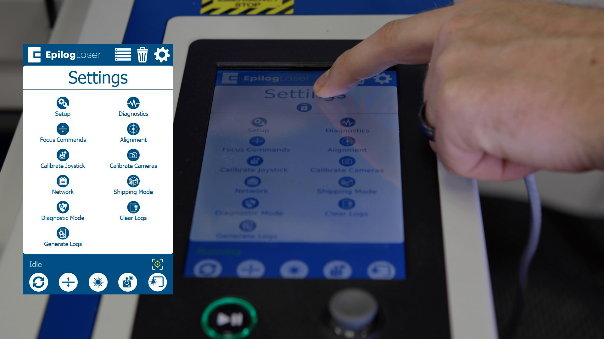
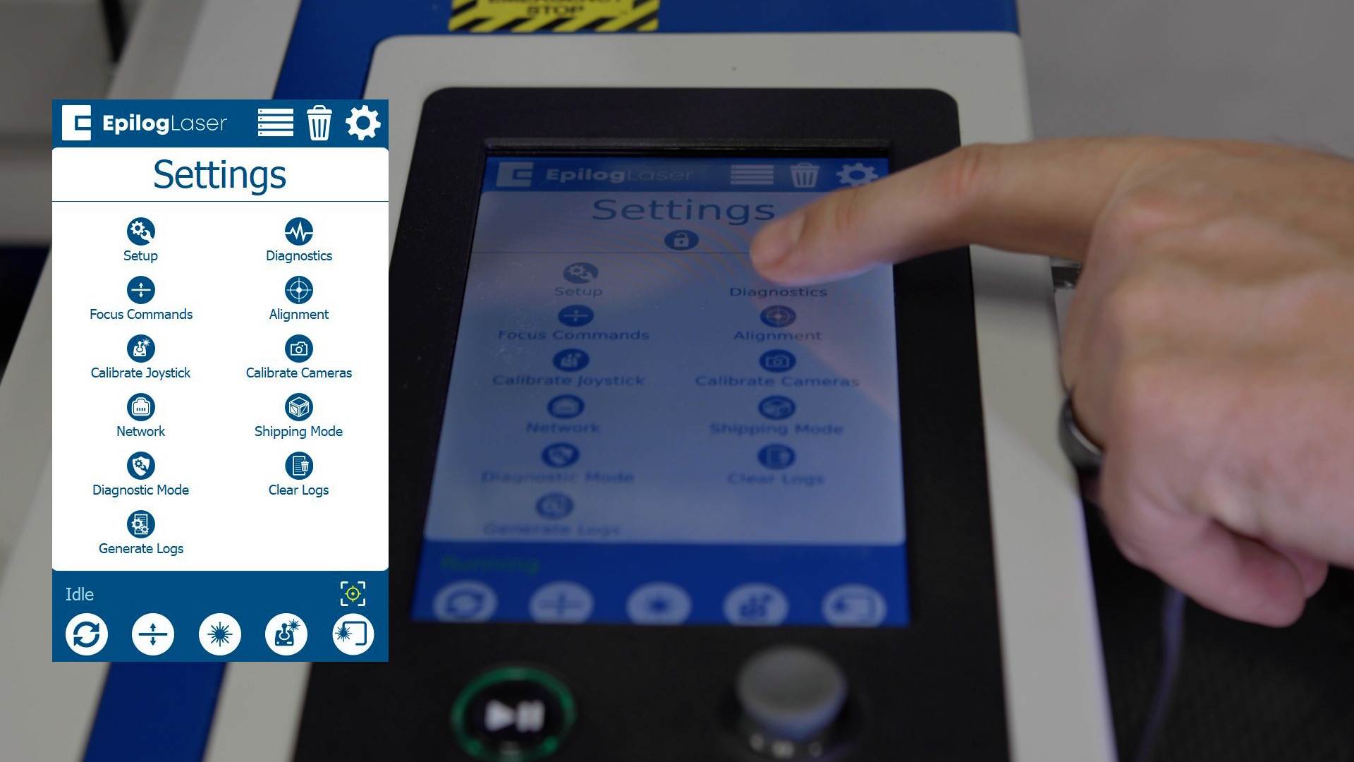
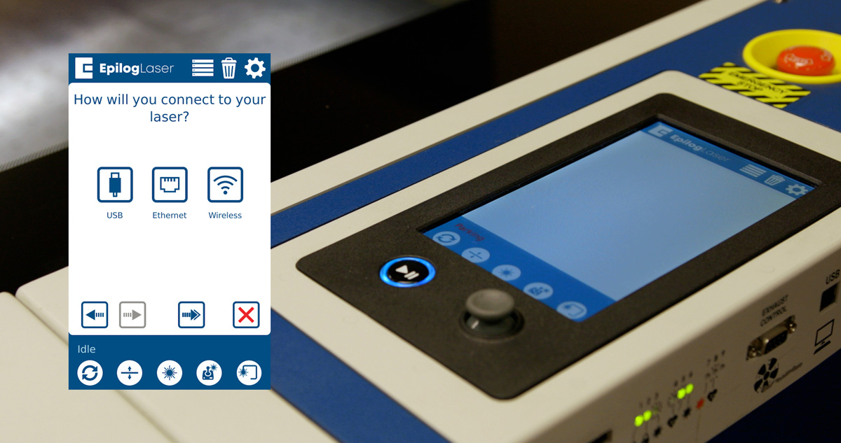
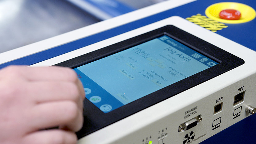
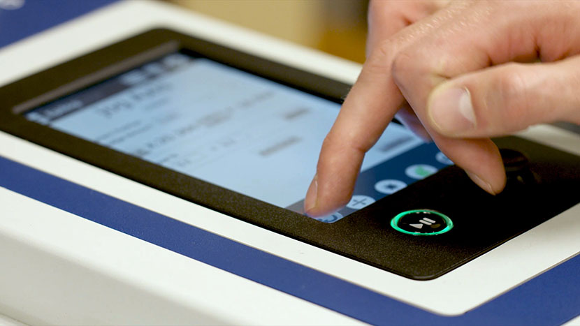
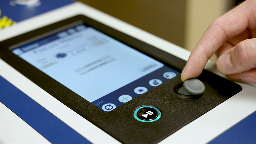
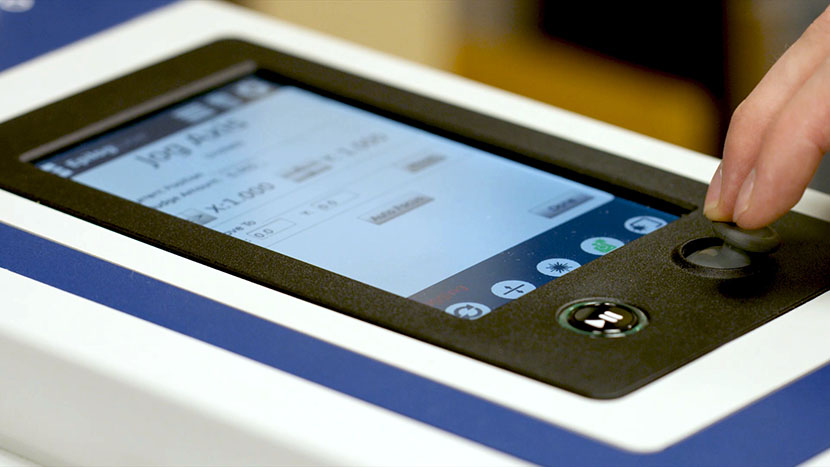
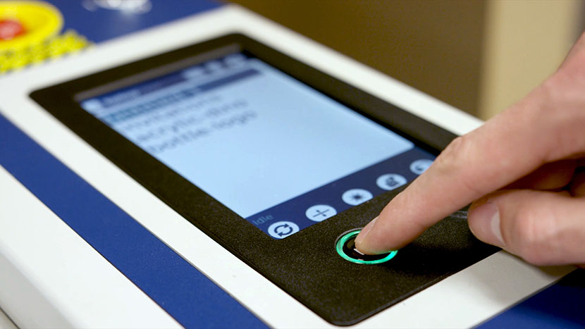
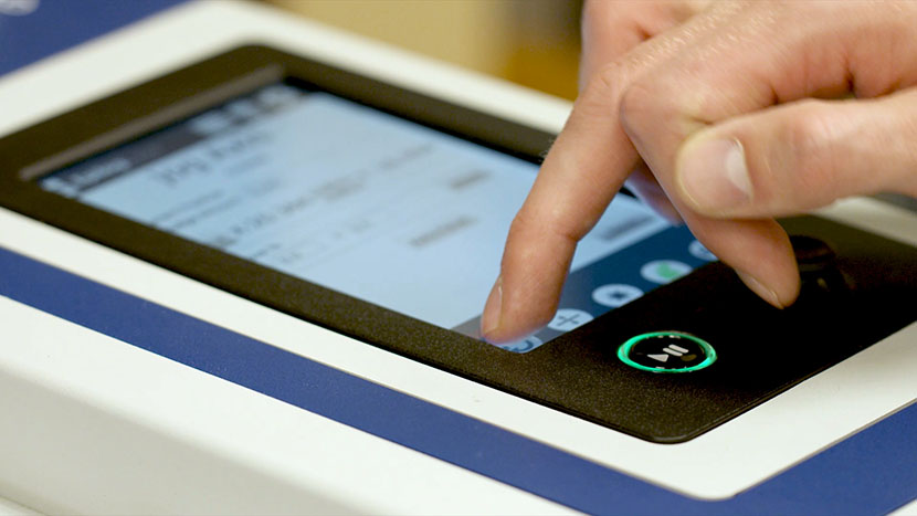
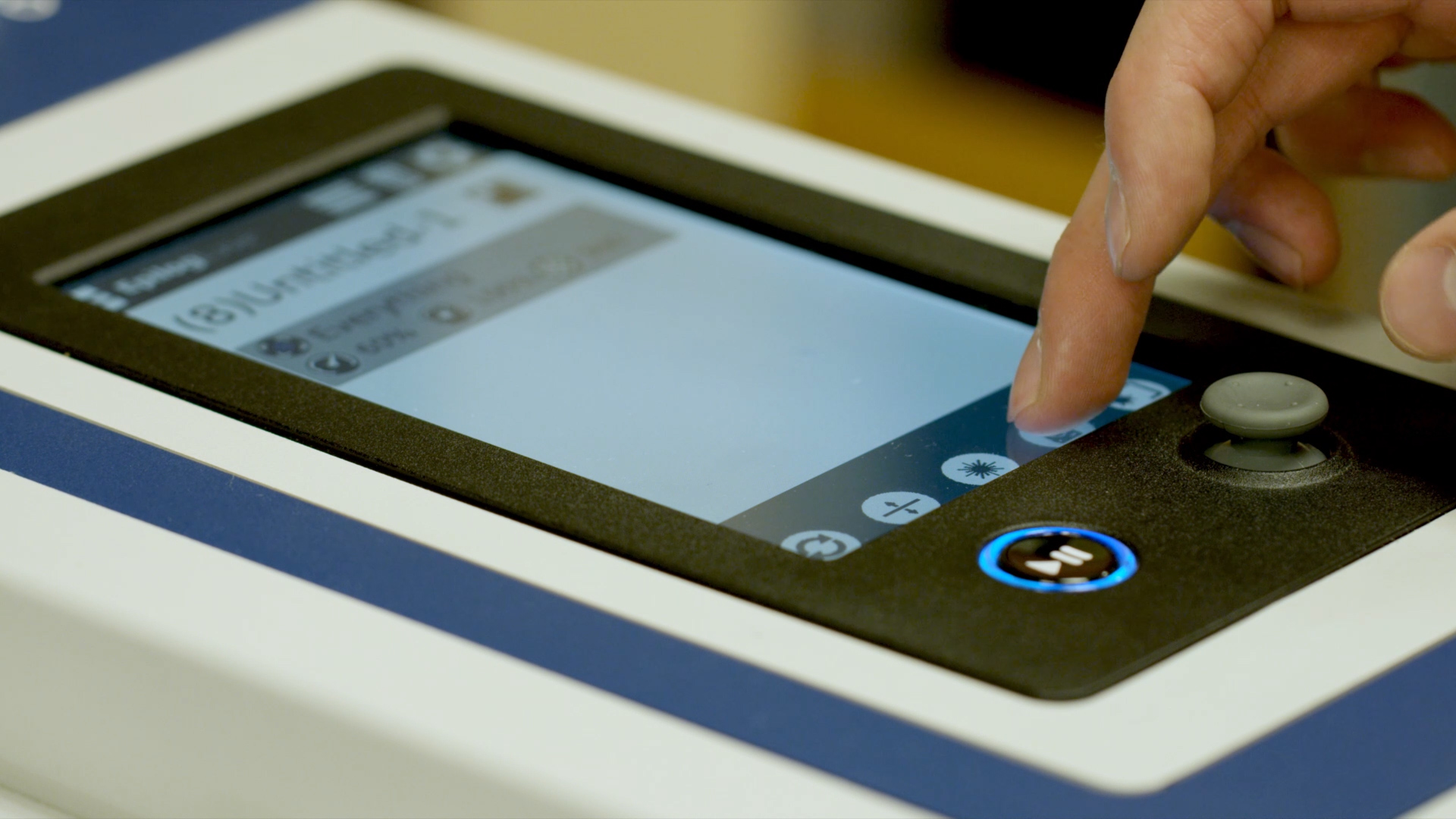
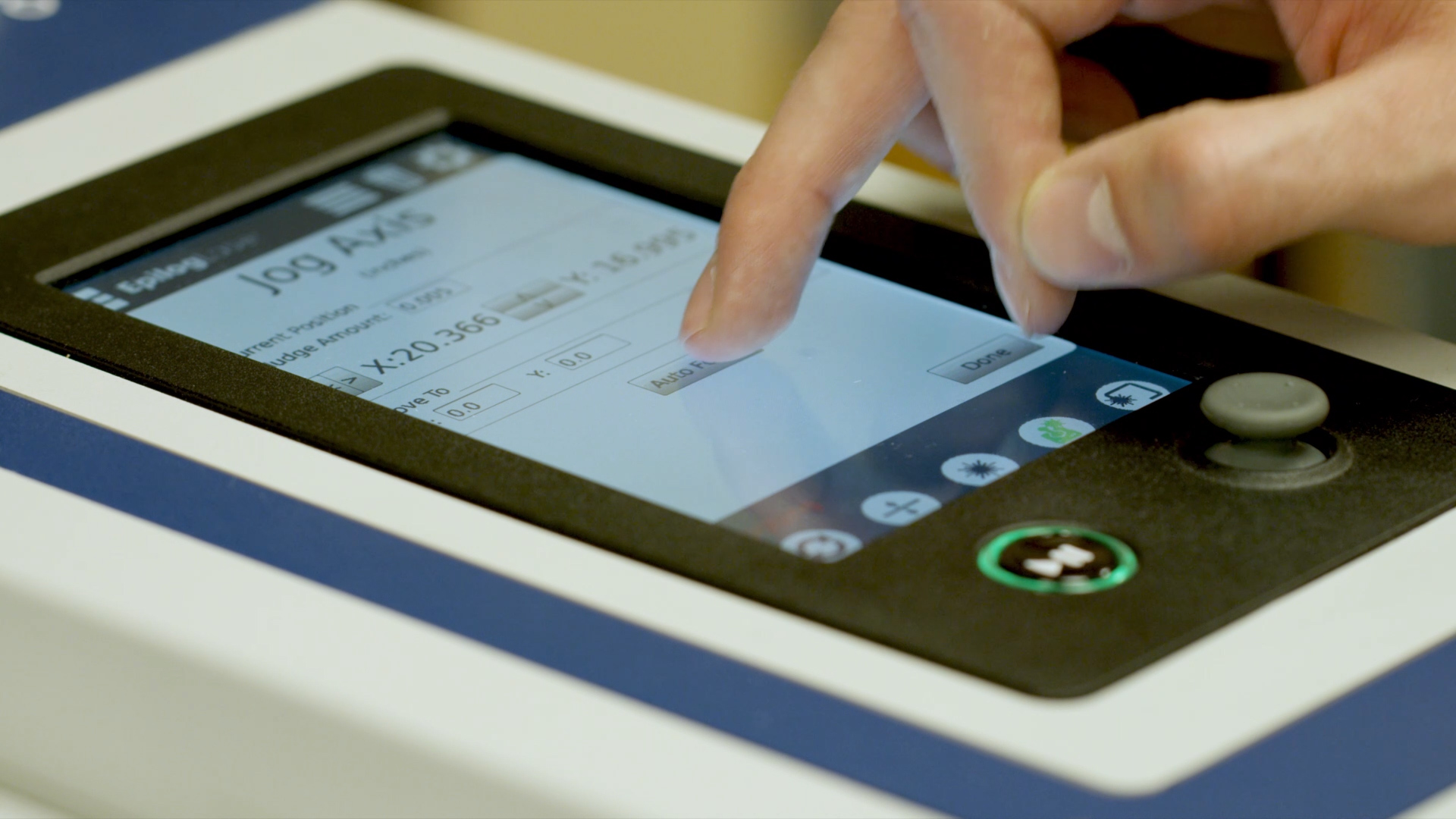
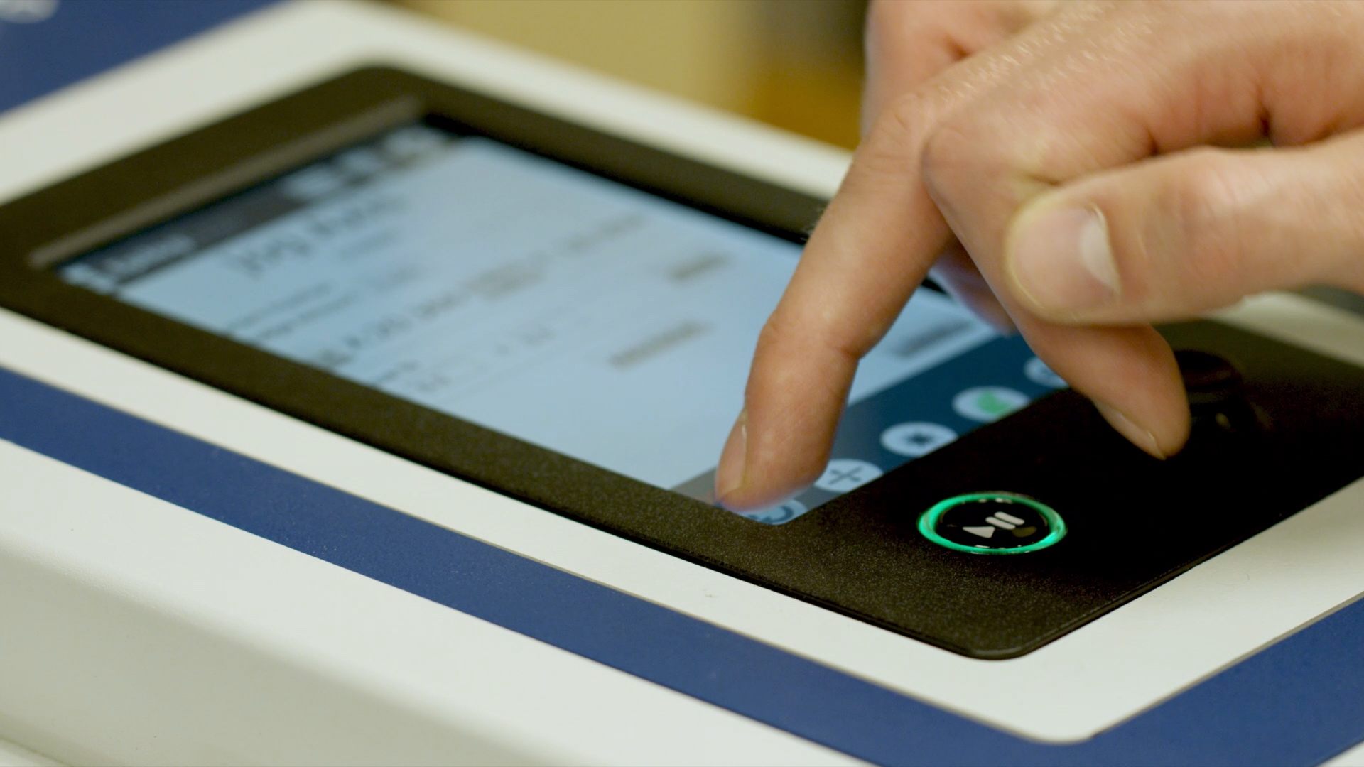
At the display panel, press the gear icon in the upper right-hand corner of the display to open the Settings menu.
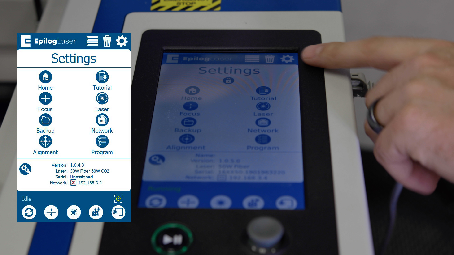
Press and hold the word “Settings” that appears at the touch of the touchpad to gain access to the Advanced Settings menu.

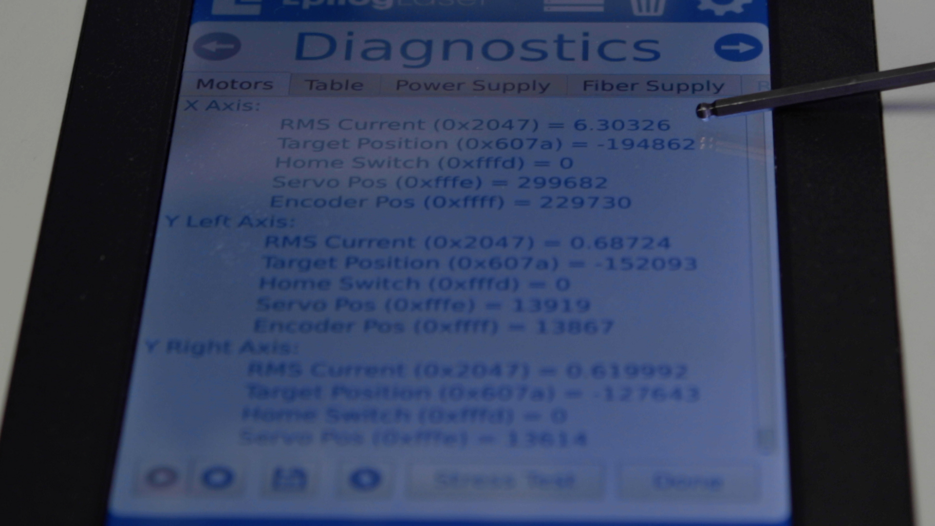
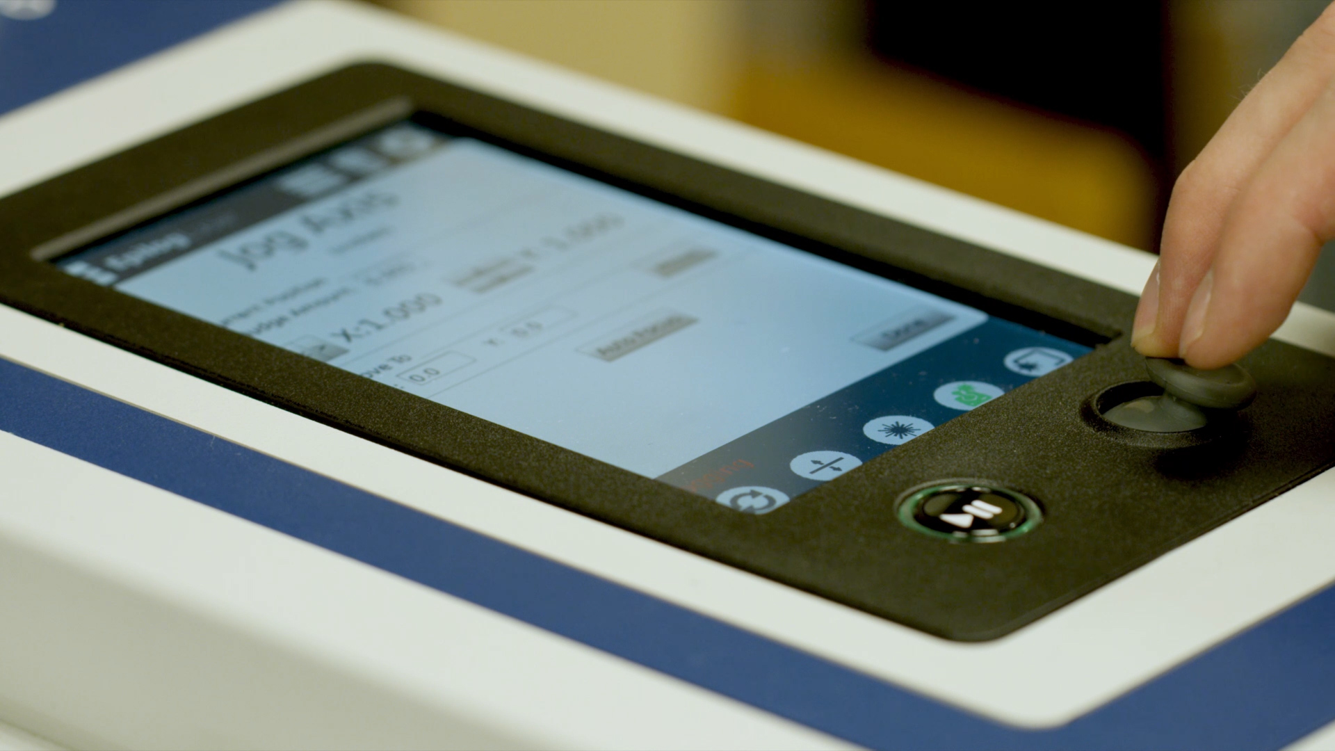
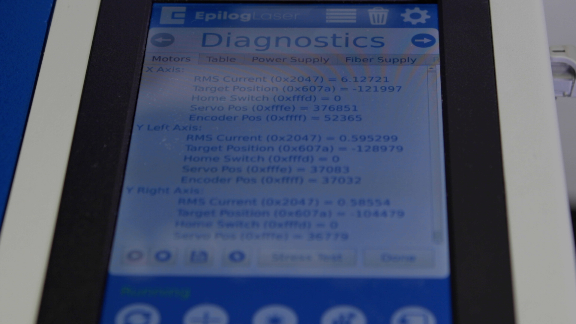
Once in the Advanced Settings menu, enter the Diagnostics menu and locate the RMS Current reading for the X-Axis Motor/Drive.

While the job is running, the x-axis motor RMS current should be between 5.2 – 6.2A.

If the RMS current is lower than this, pause the job and increase the tension on the x-axis belt by tightening the two (2) 7/64” tensioner screws on the x-axis idler assembly.
If the RMS current is higher than this, pause the job and decrease the tension on the x-axis belt by loosening the two (2) 7/64” tensioner screws on the x-axis idler assembly.
Once the optimal RMS current value has been achieved, tighten the four 7/64” idler mounting screws at the front of the x-axis assembly and the four 7/64” idler mounting screws at the rear of the x-axis assembly.
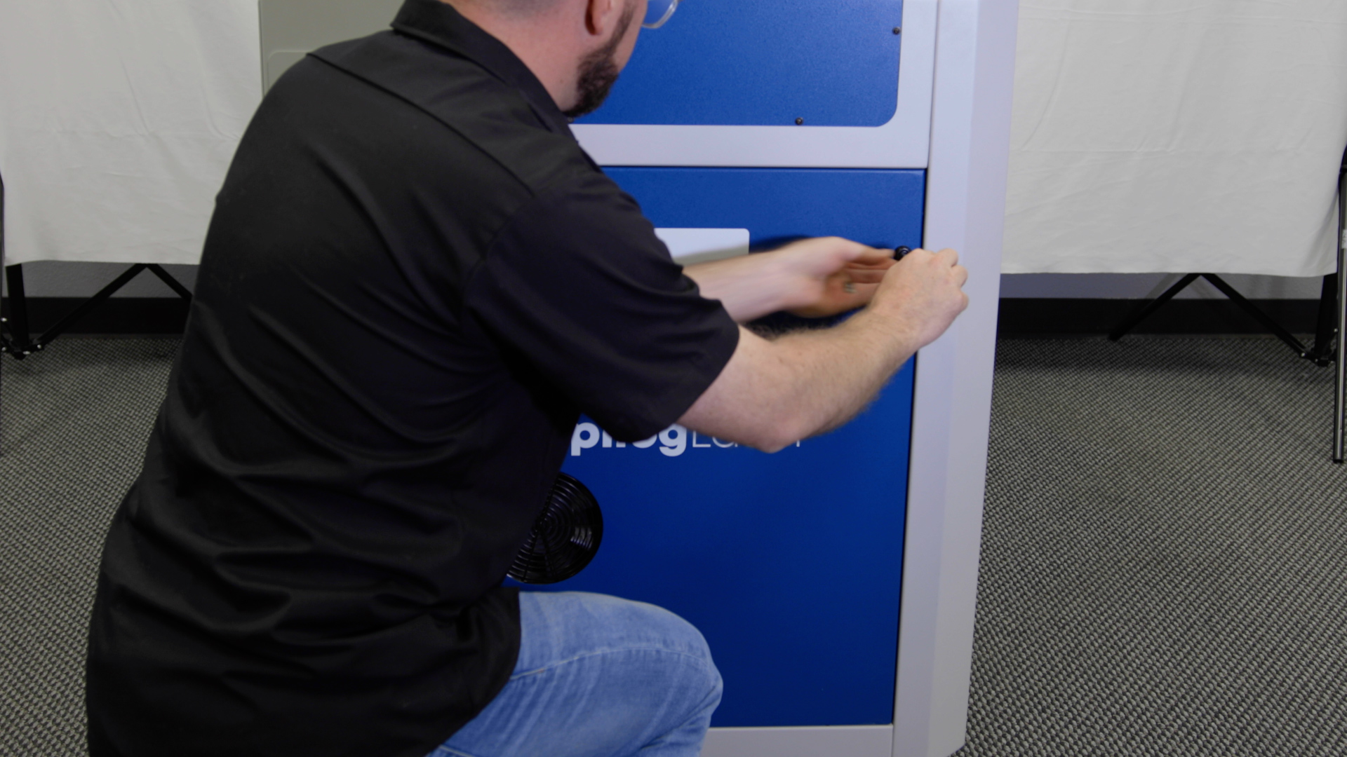
Replace both the left and right panels of the engraver.

You have now completed replacing the Reducer Drive Assembly on the Fusion Pro.