Remove Panels
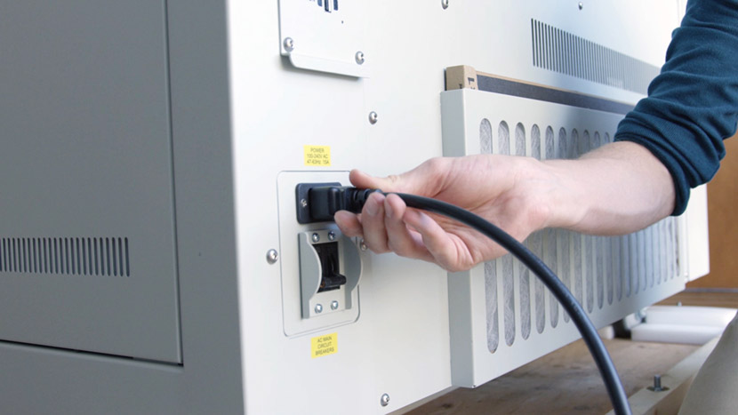
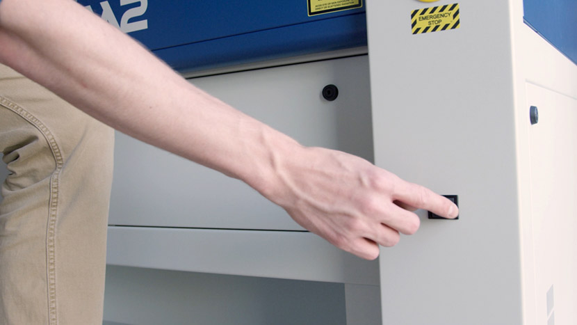
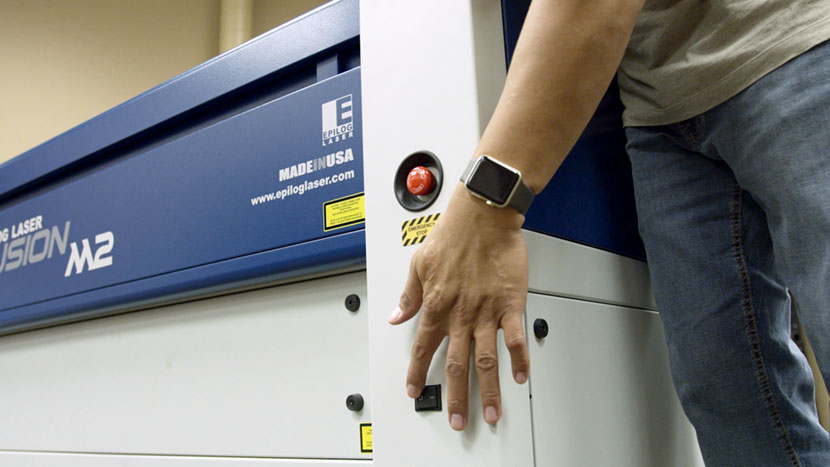
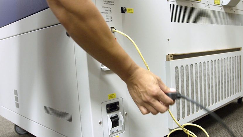
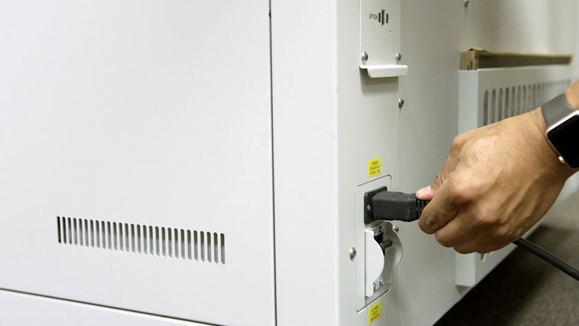
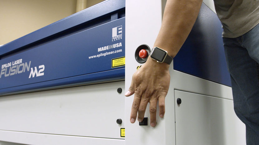
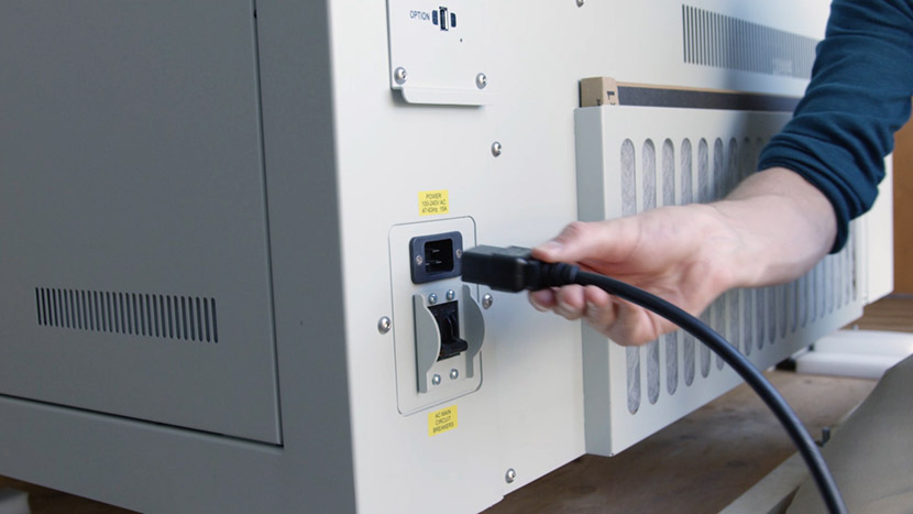
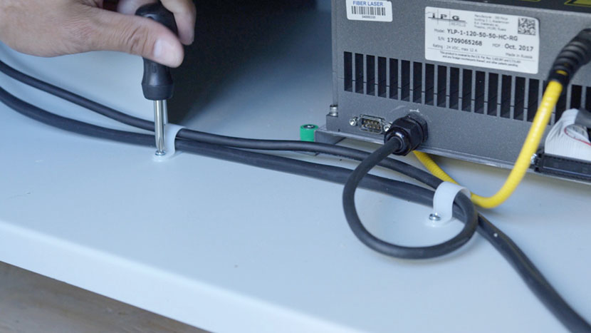
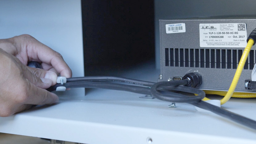
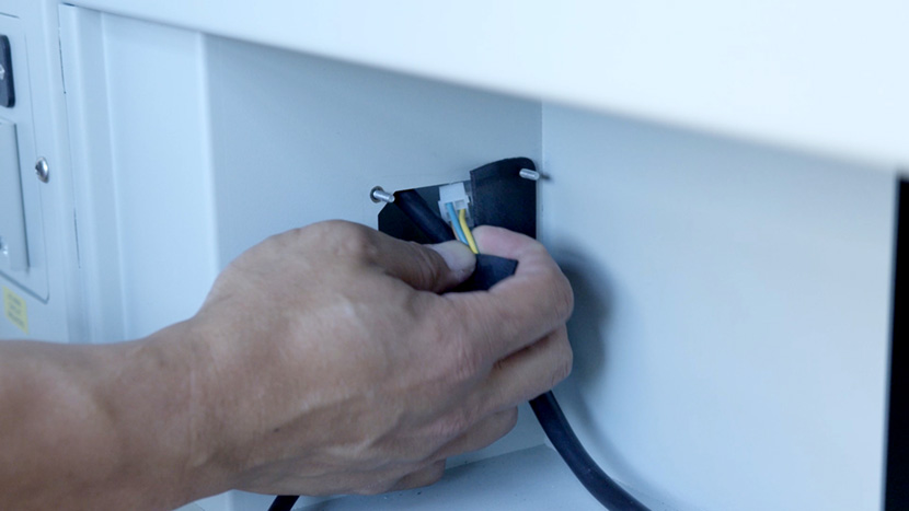
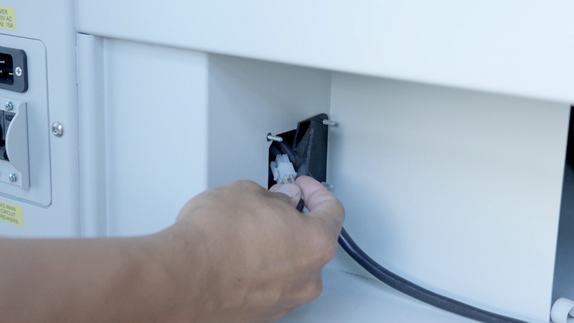
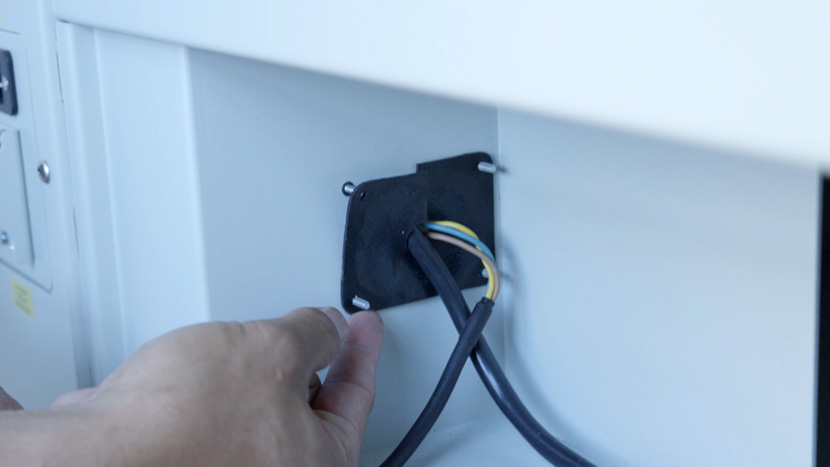
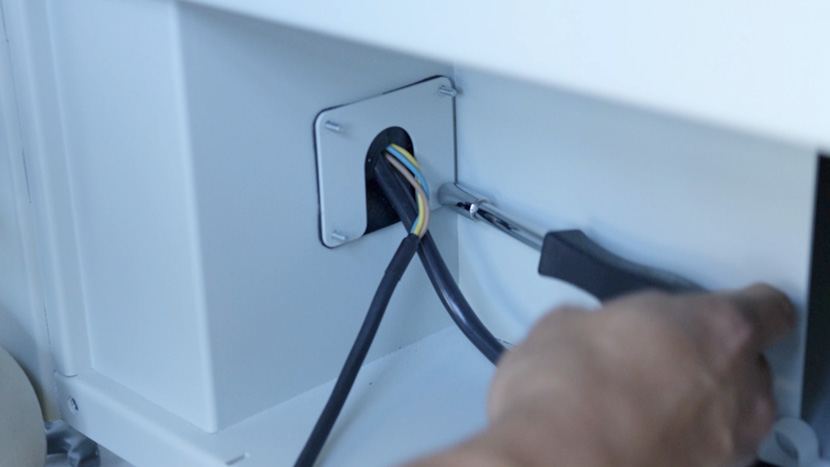
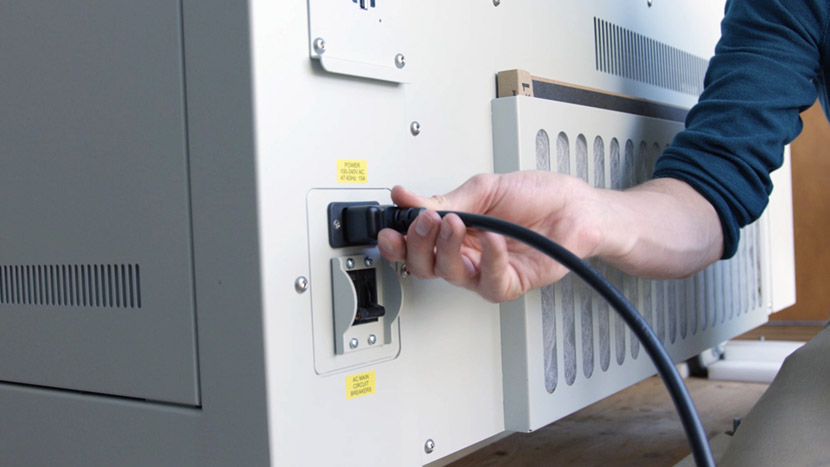
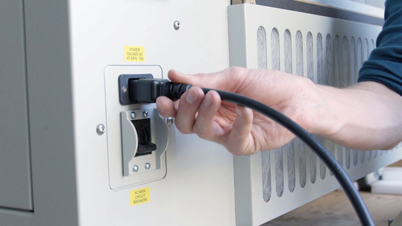
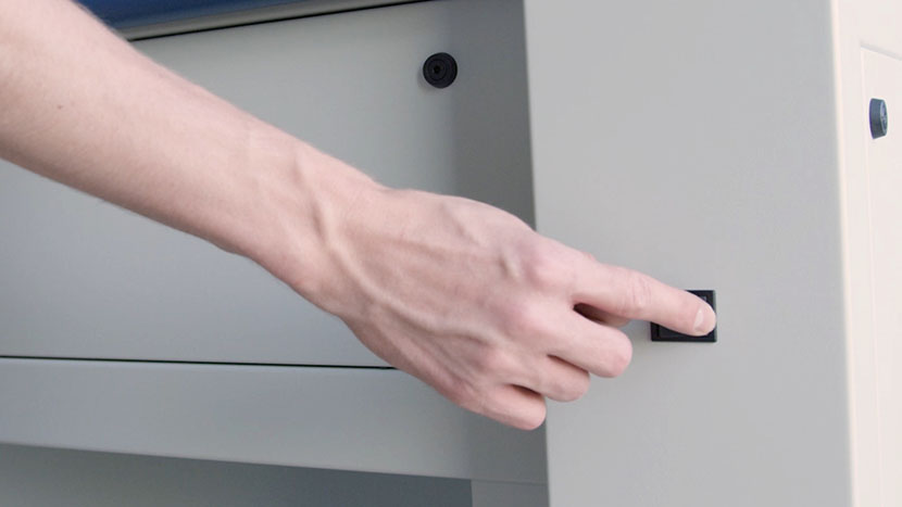
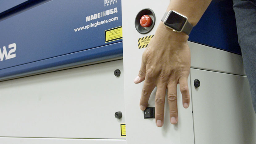
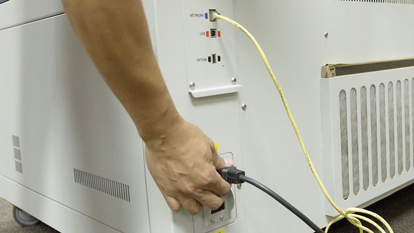
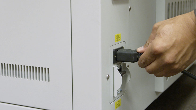
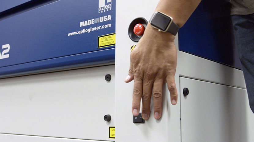
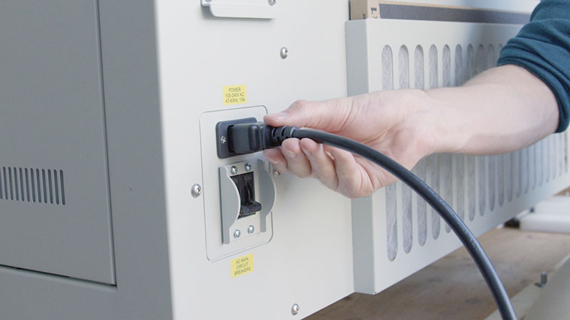
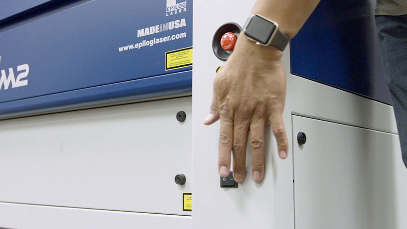
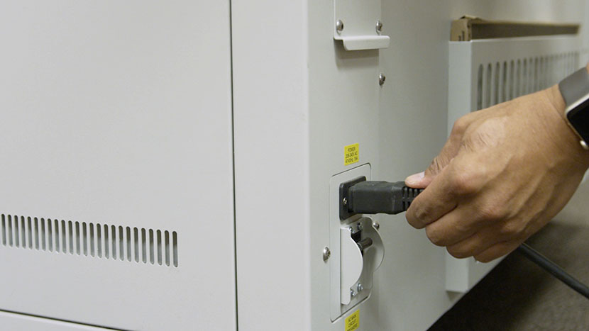
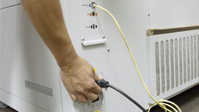
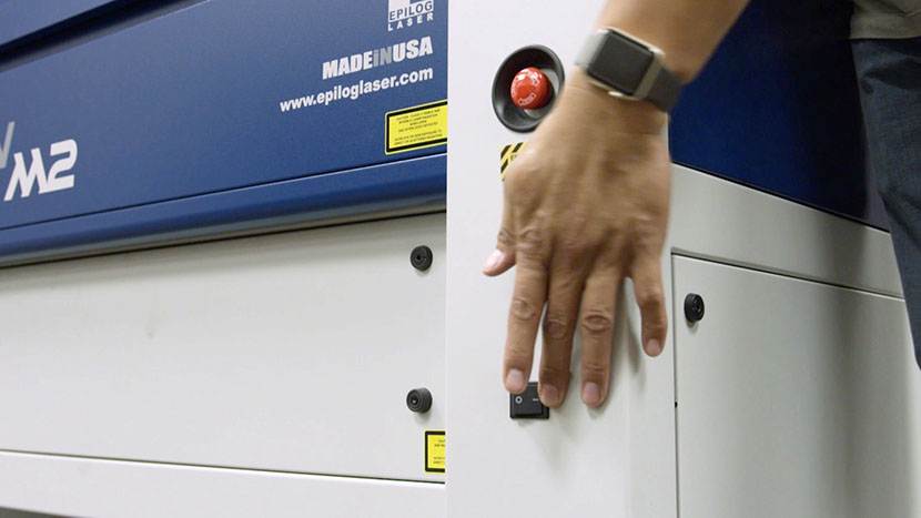
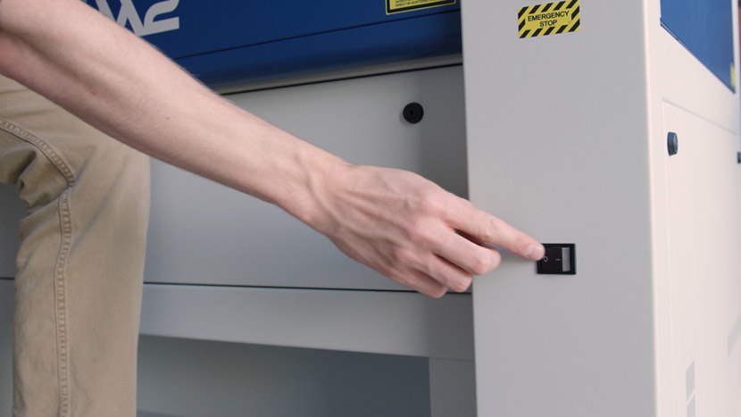
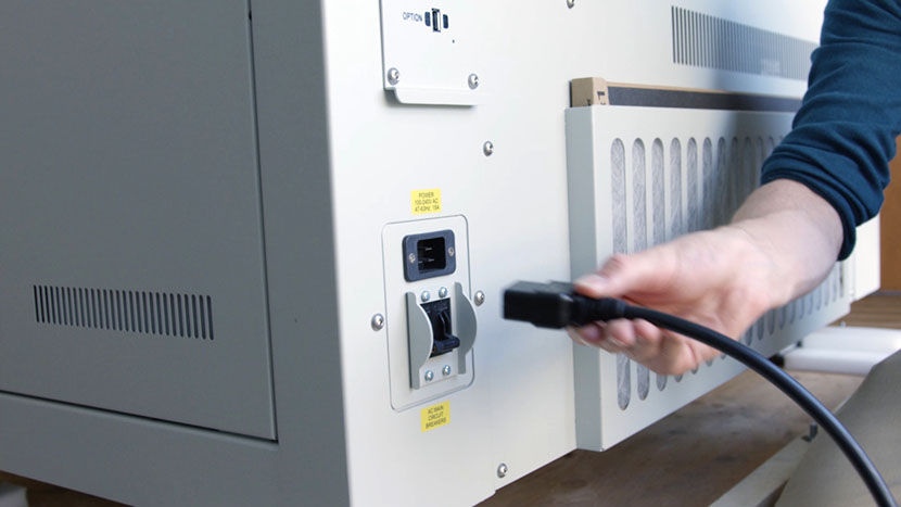
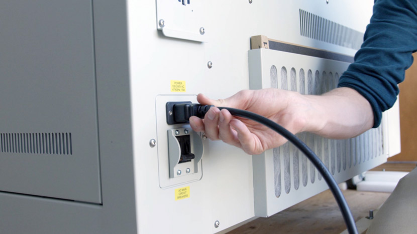
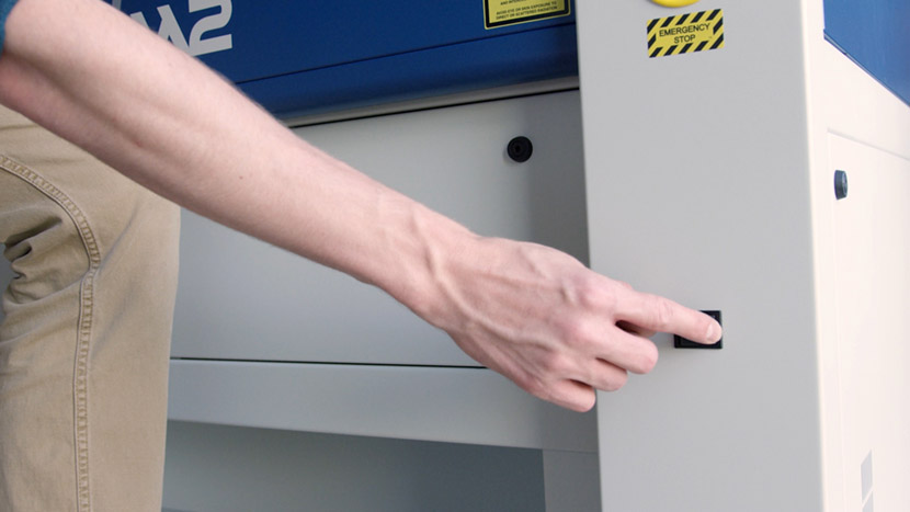
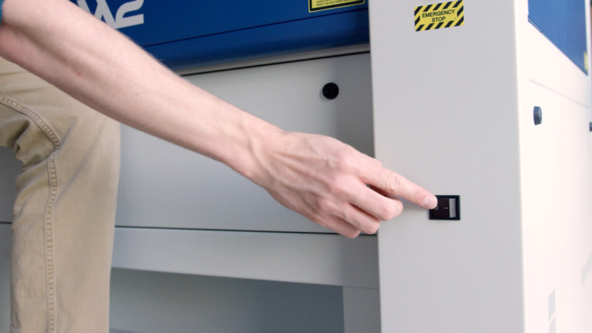
Shut off the laser and remove the power cord from the machine.

We’ll begin by replacing the y-axis on the right-hand side of the machine.
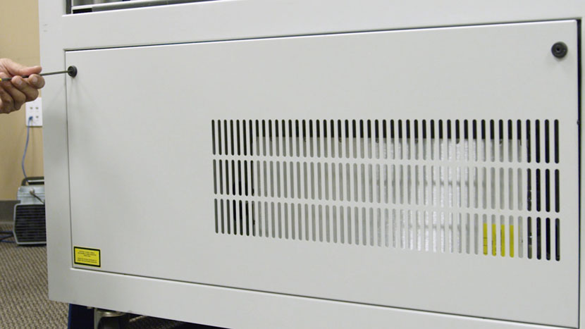
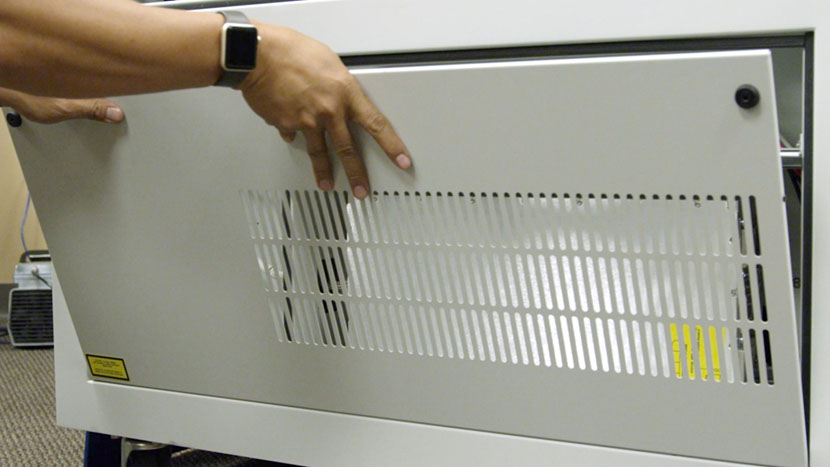
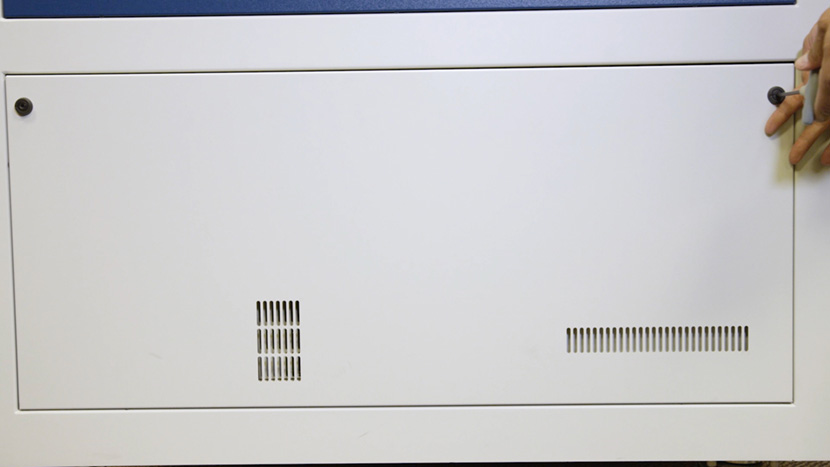
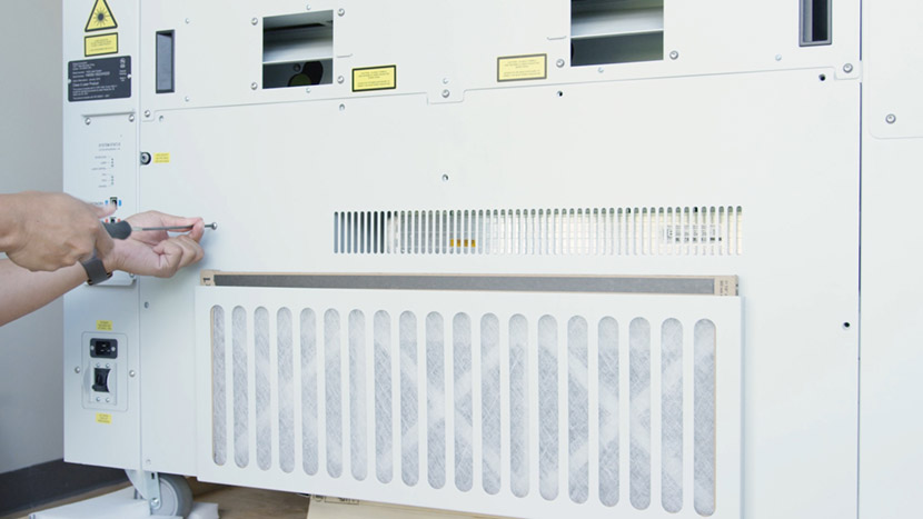
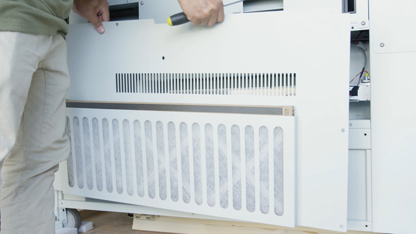
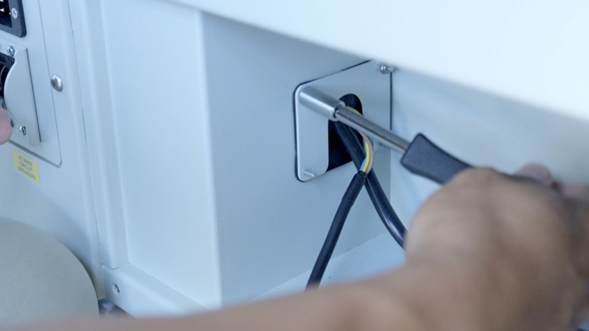
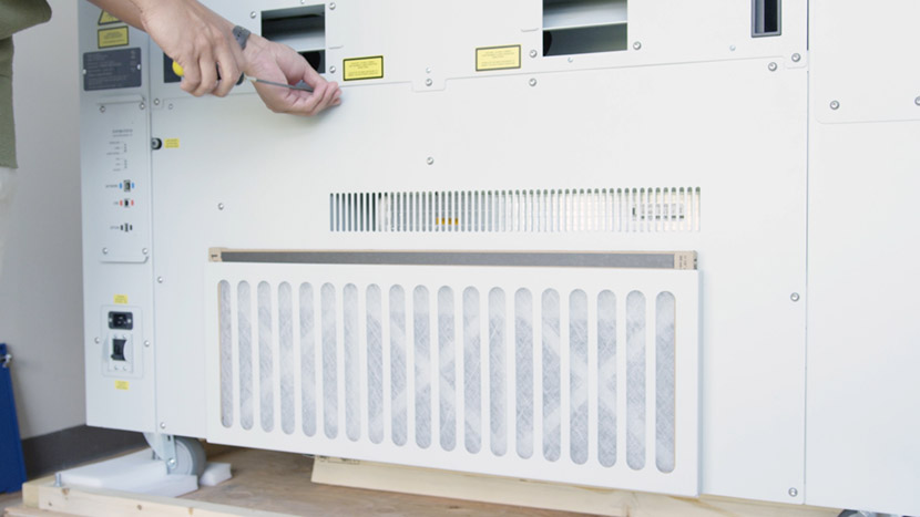
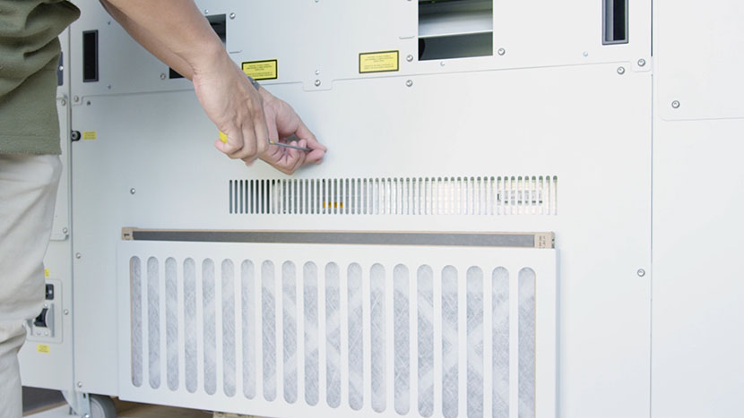
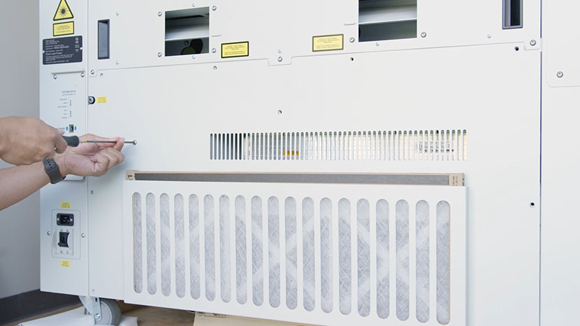
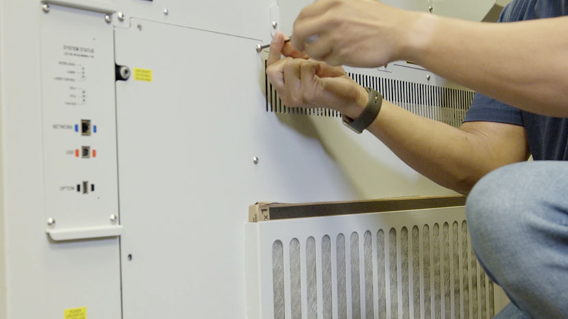
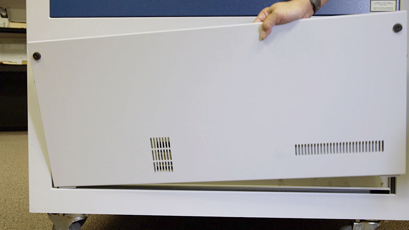
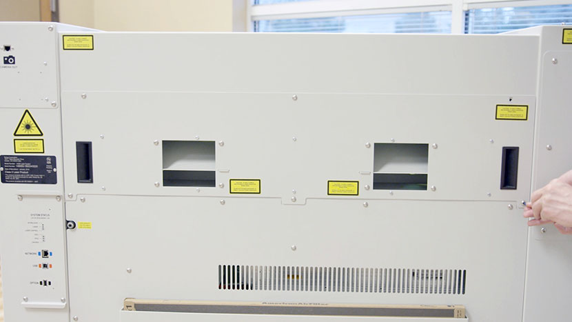
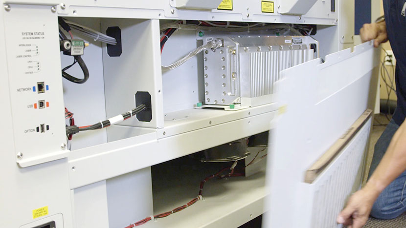
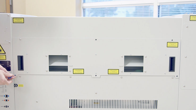
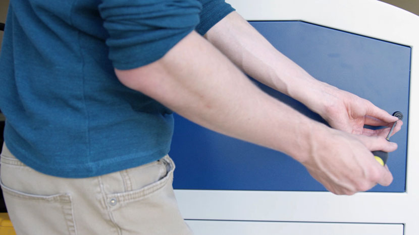
Use a 5/32” hex key to remove the exhaust plenum on the rear of the machine.
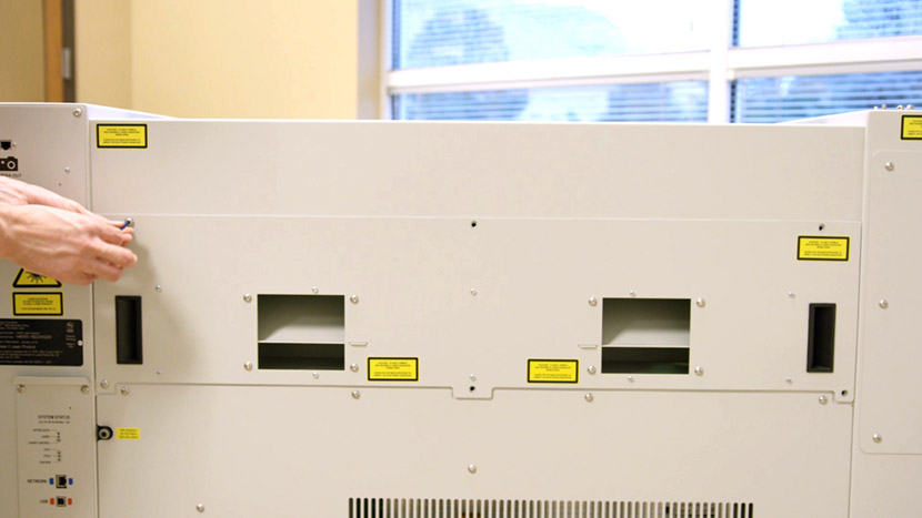
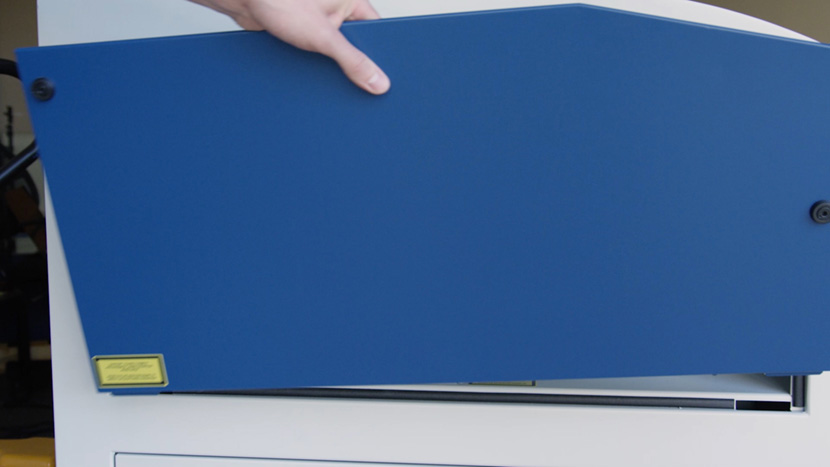
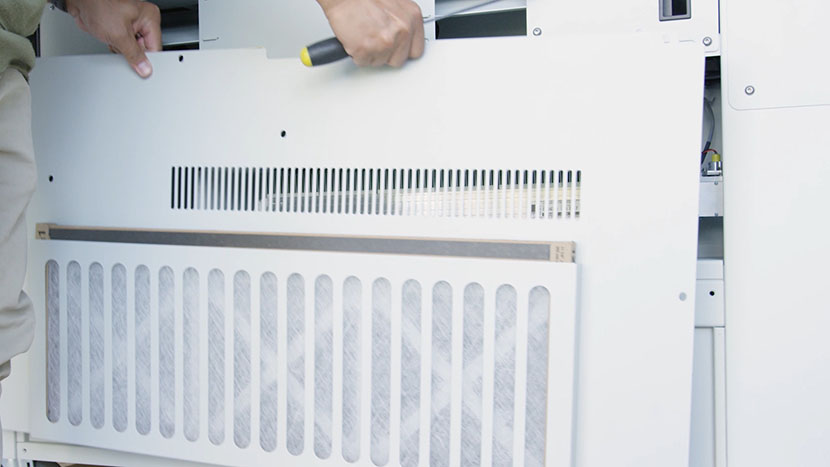
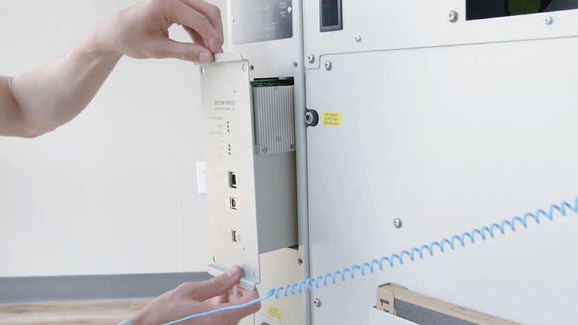
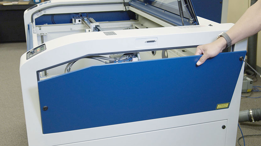
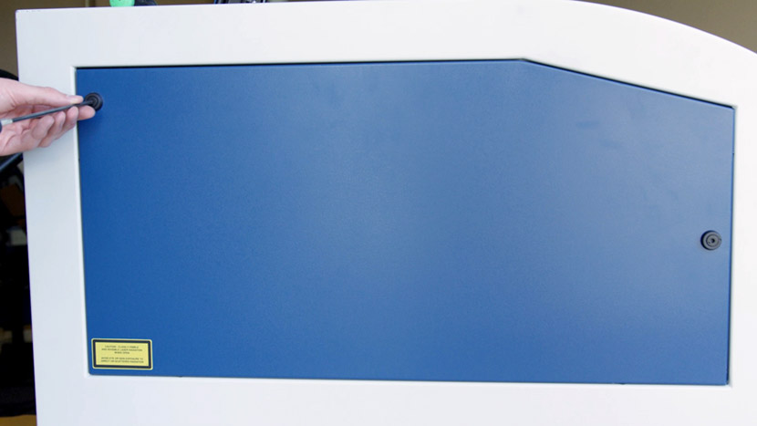
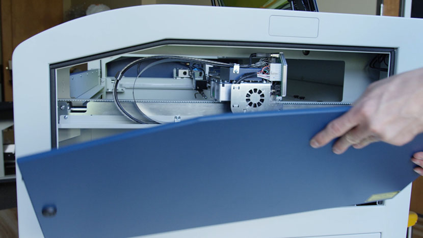
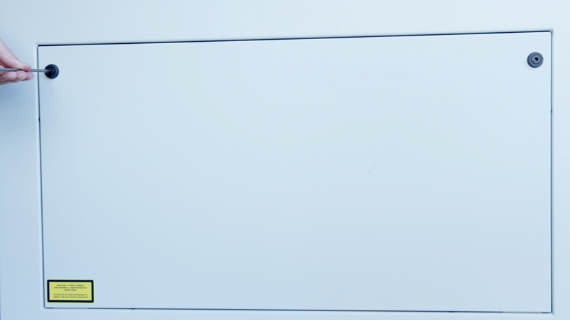
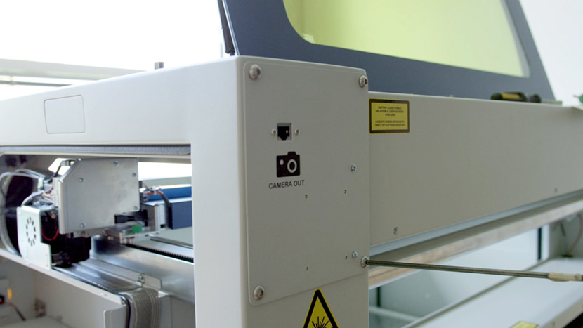
Then remove the small panel in the top left corner.
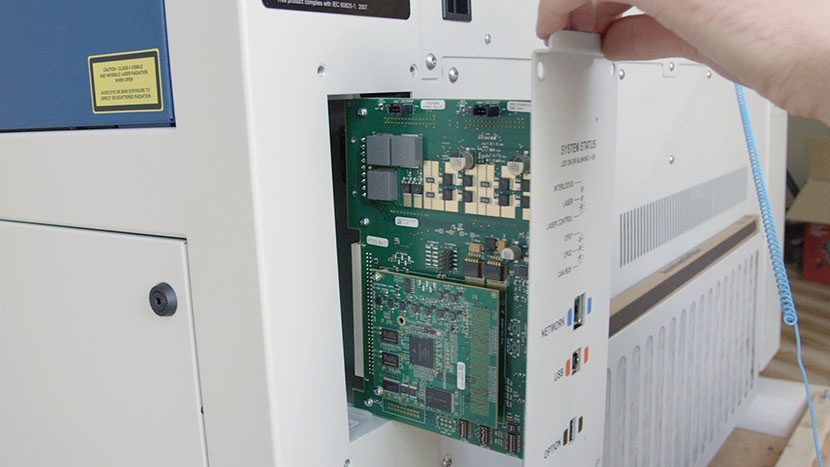
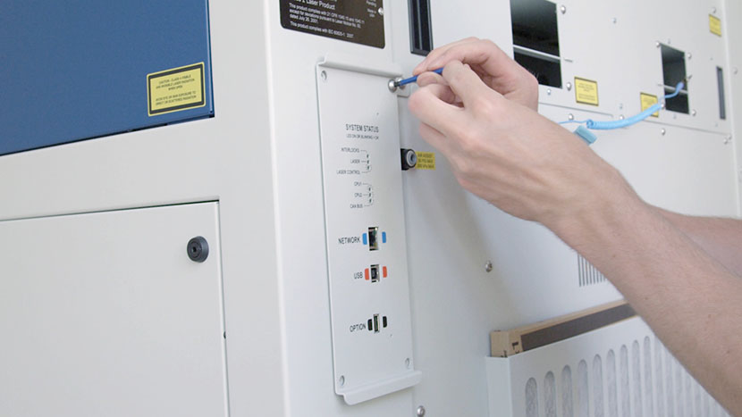
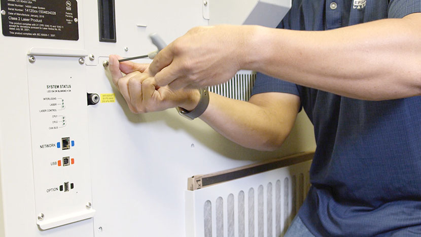
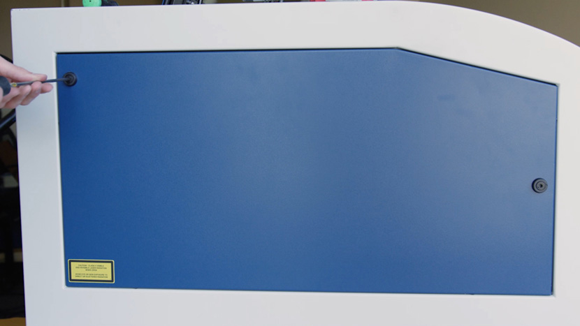
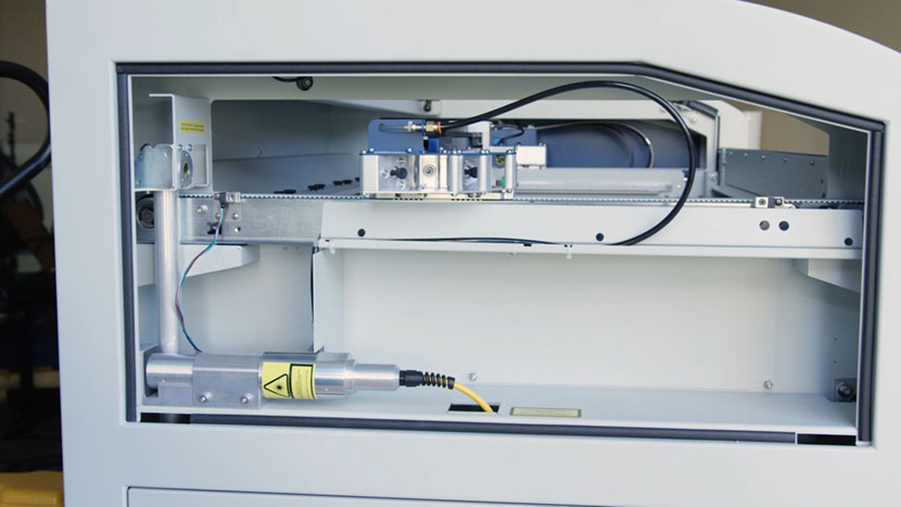
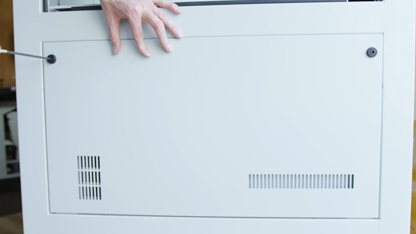
Next use a 5/32” hex key to remove the top access panel on the left side of the machine, as well as both the top and bottom access panels on the right side of the machine.

Remove X-Axis Assembly
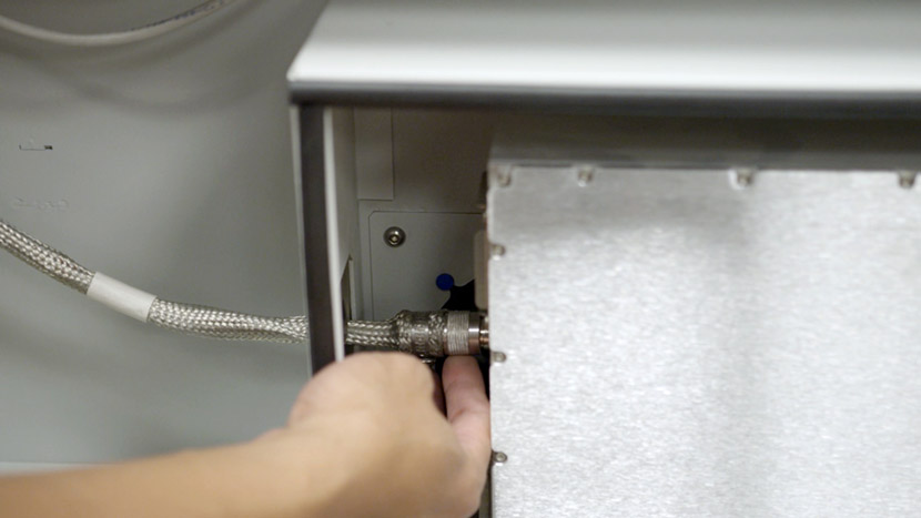
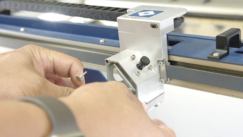
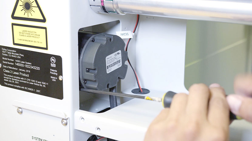
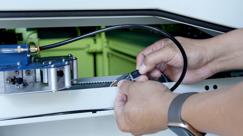
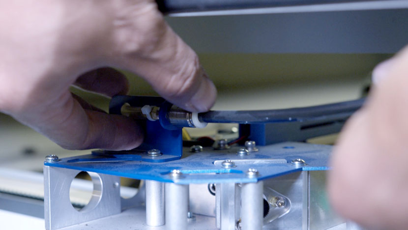
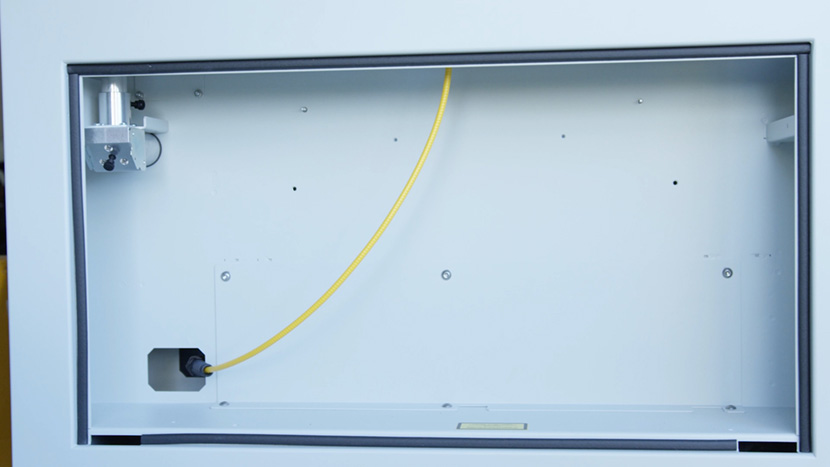
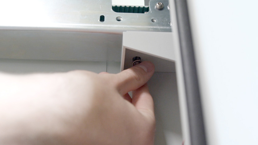
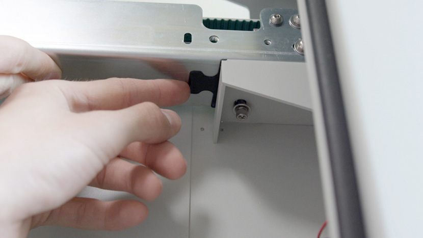
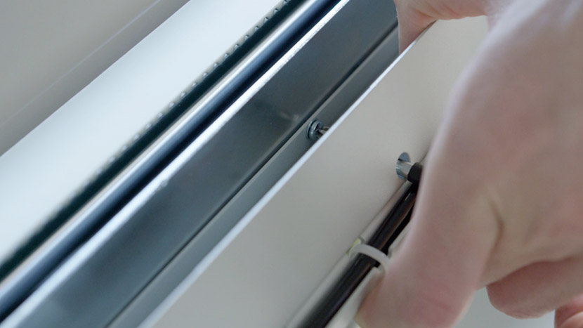
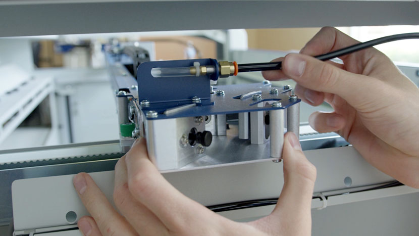
On the left side of the machine, find and disconnect the Air Assist tube from the x-axis assembly. Press the ring toward the rear of the engraver while pulling on the black tube.
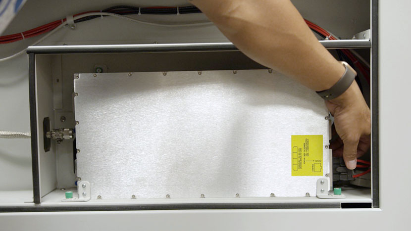
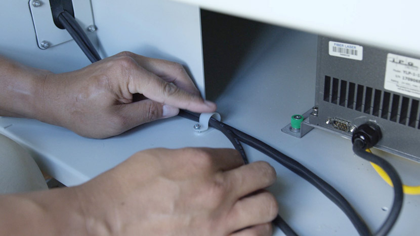
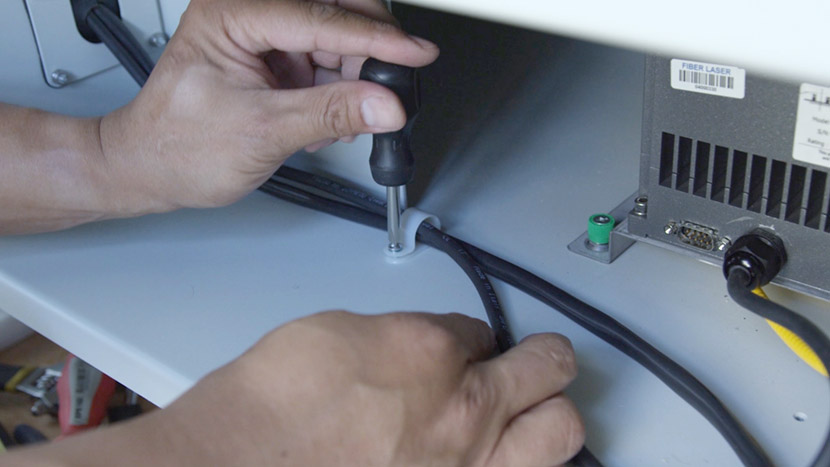
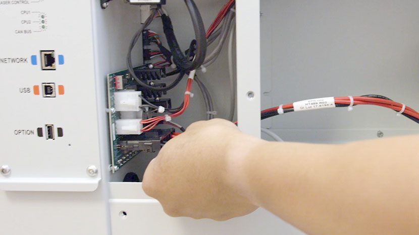
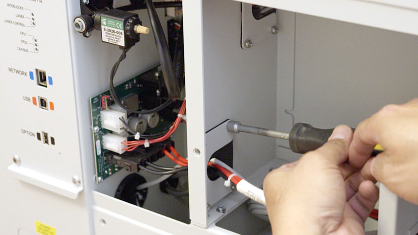
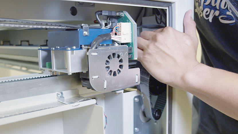
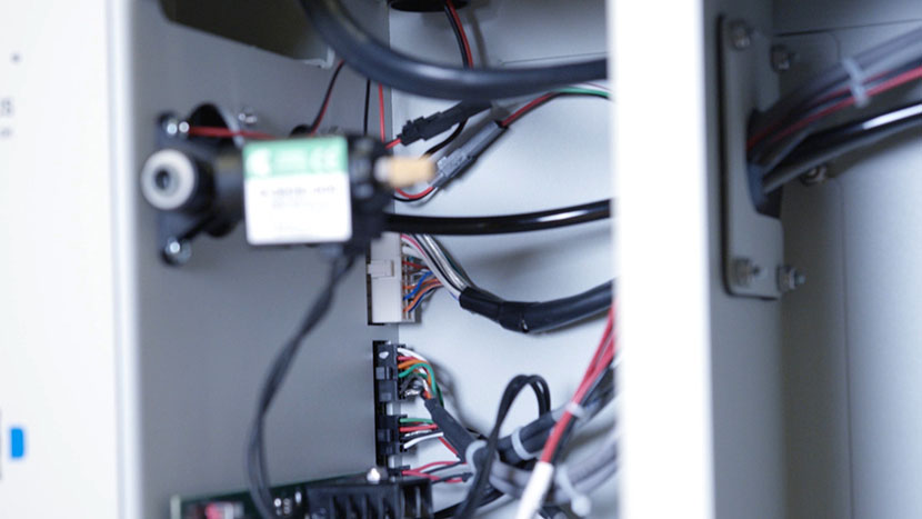
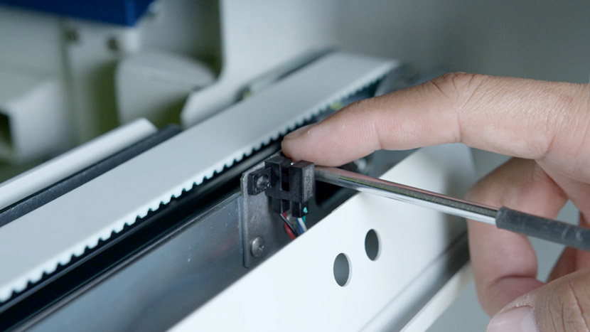
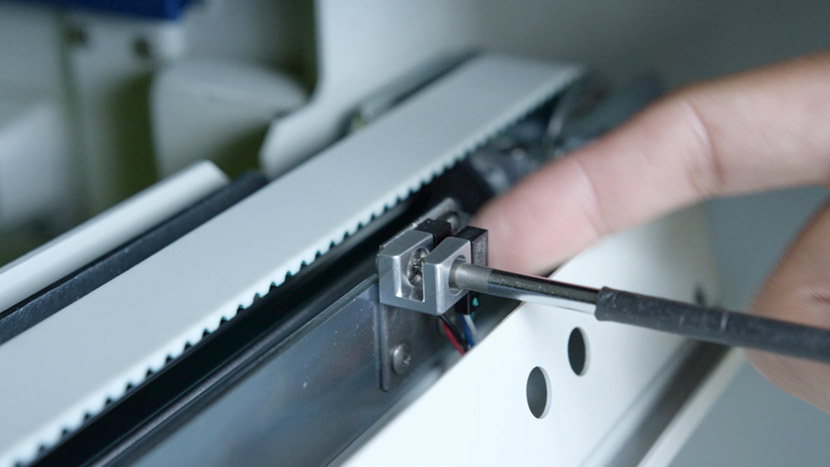
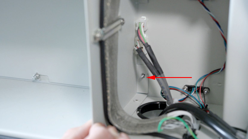
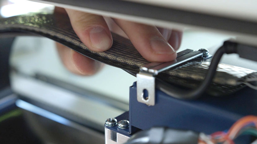
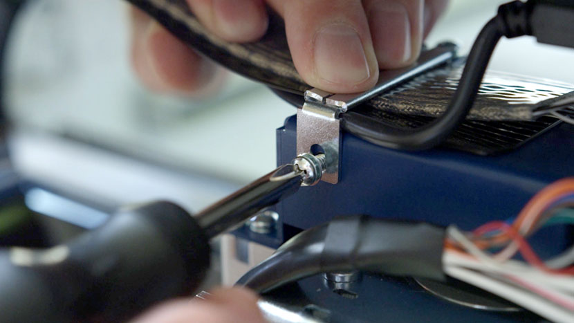
The wire harness and its plastic guard are held secure by the wire harness clamp. With a short or offset Philips head screw driver remove the clamp screws then set the clamp aside.
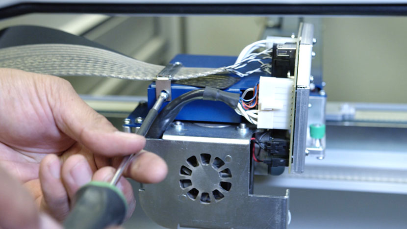
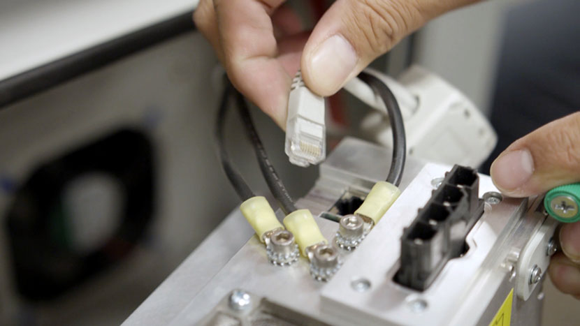
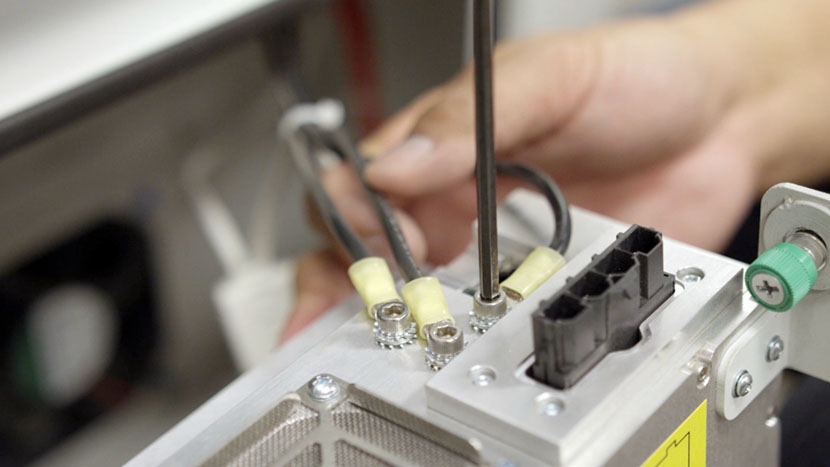
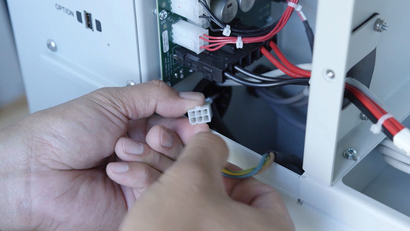
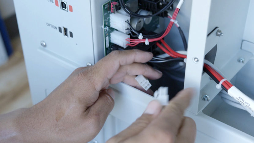
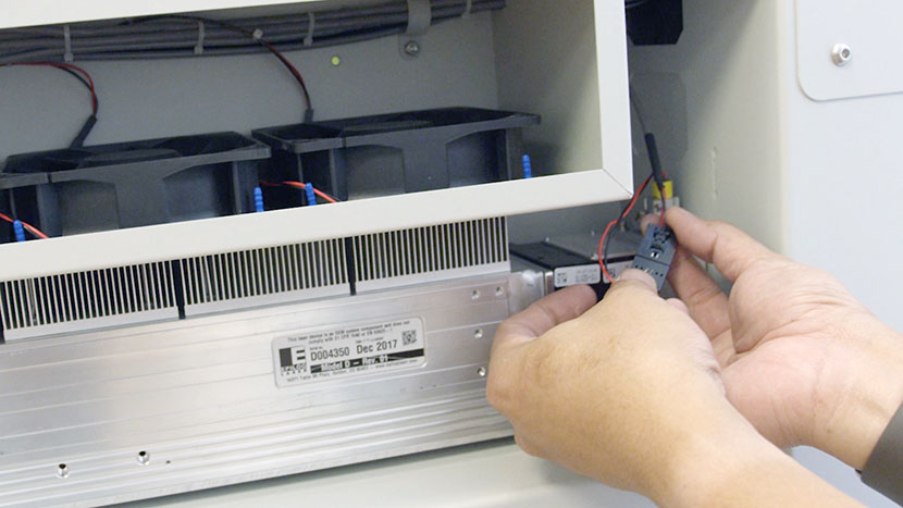
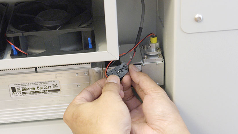
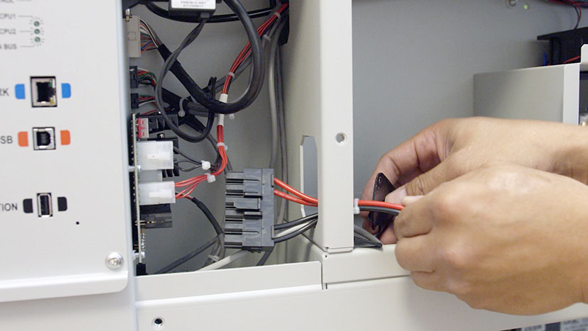
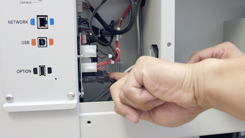
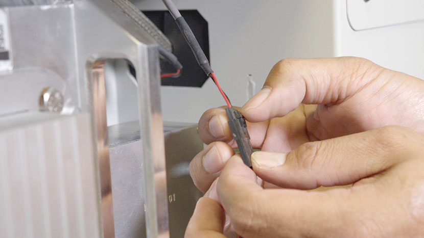
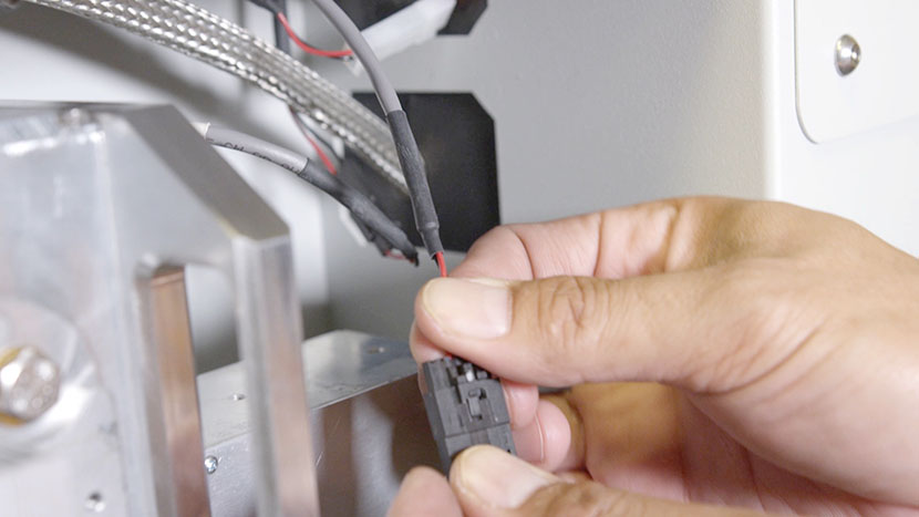
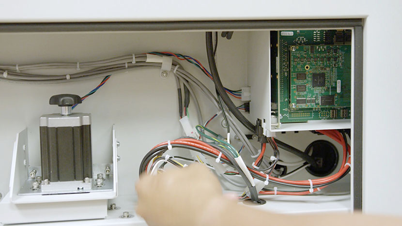
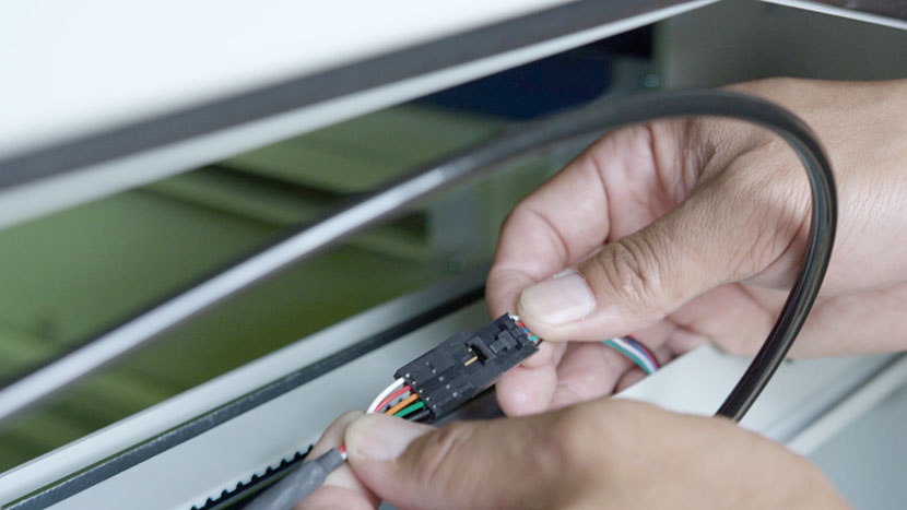
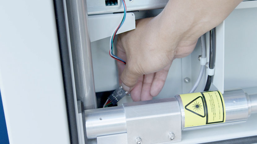
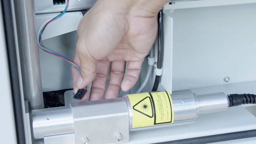
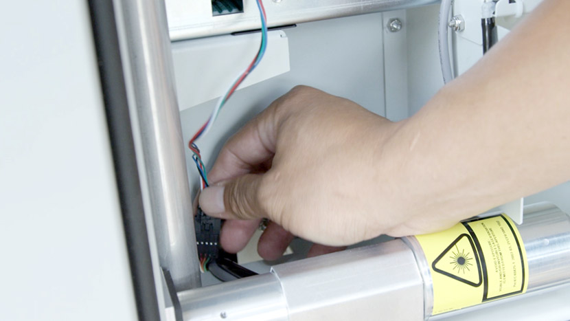
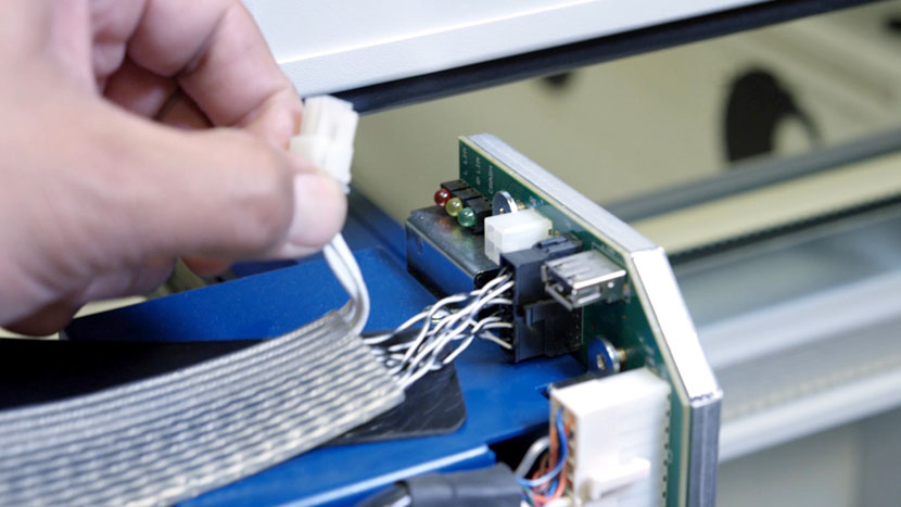
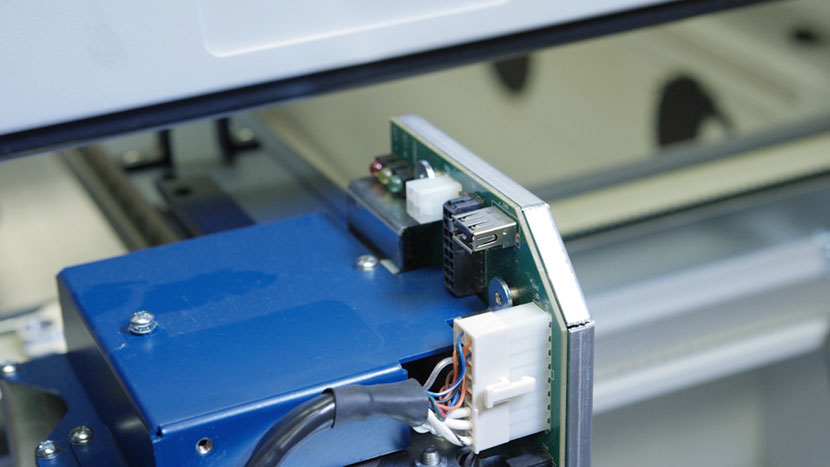
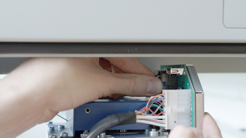
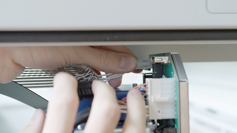
Disconnect the white connector from its socket by squeezing the lock tab on the bottom of the connector and pulling it away from the circuit board. Remove the black connector as well.
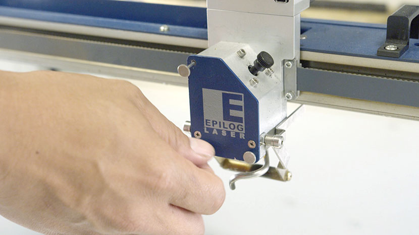
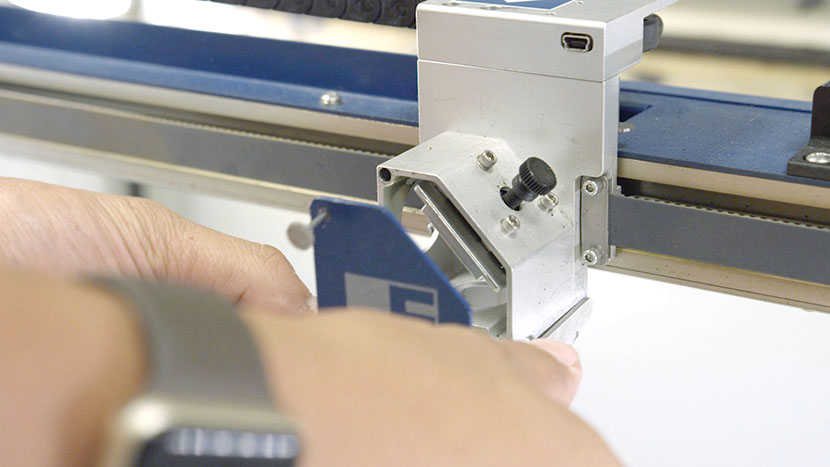
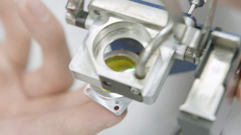
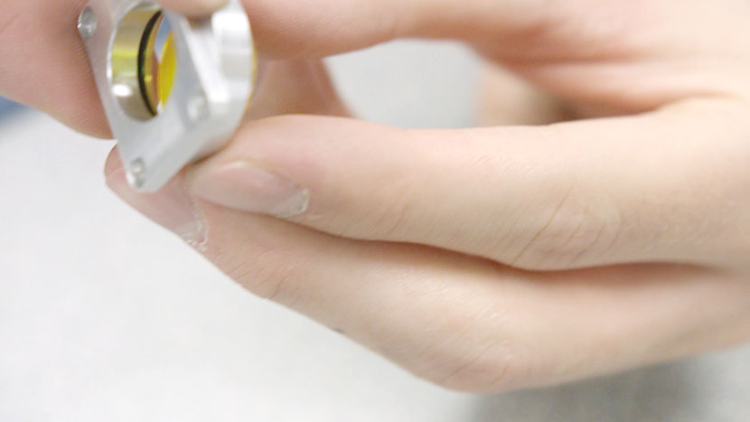
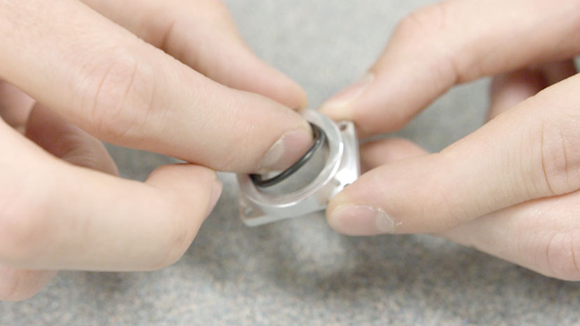
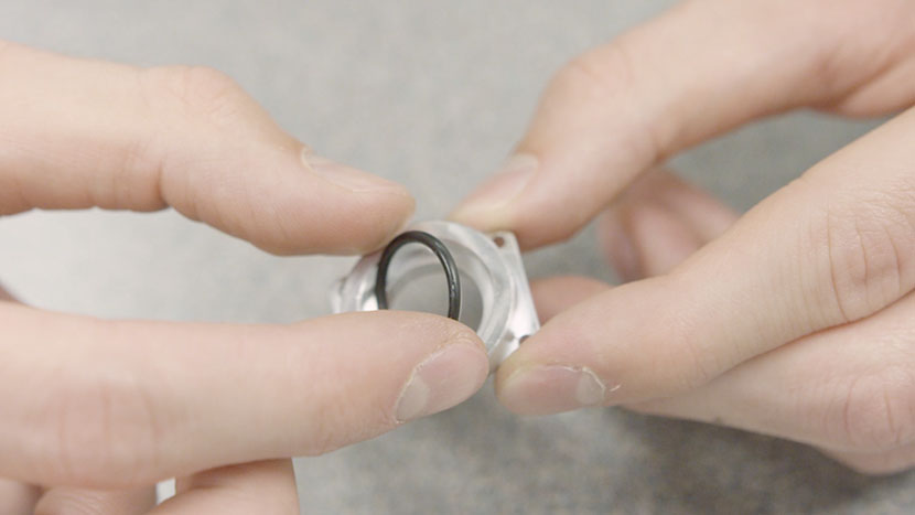
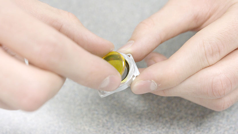
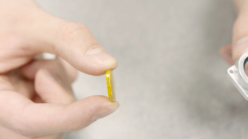
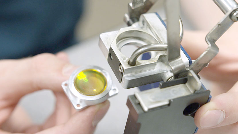
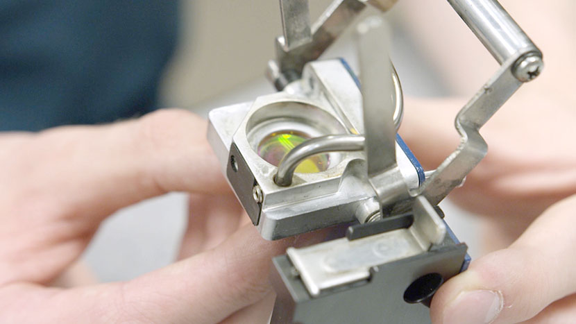
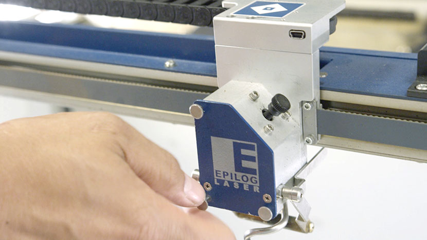
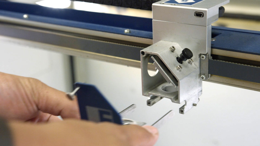
Then remove the lens assembly by loosening the 3 thumb screws on its front face until they spin freely. They are captive screws and will not come out of the assembly.

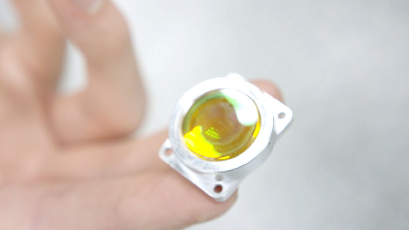
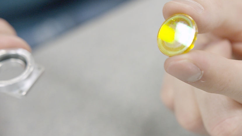
Slide the assembly out of its housing and set it aside.
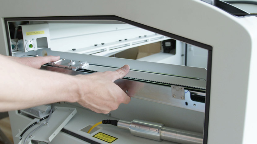
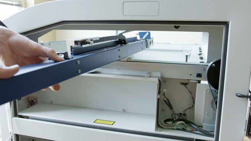
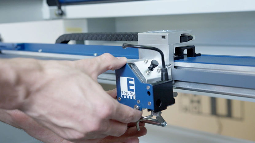
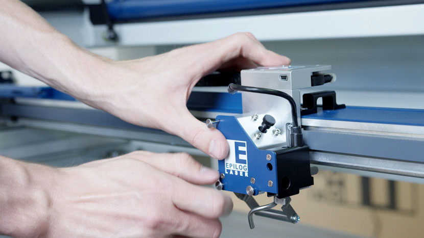
Now it’s time to remove the x-axis assembly.
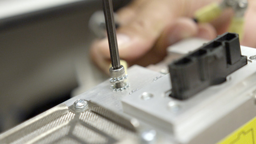
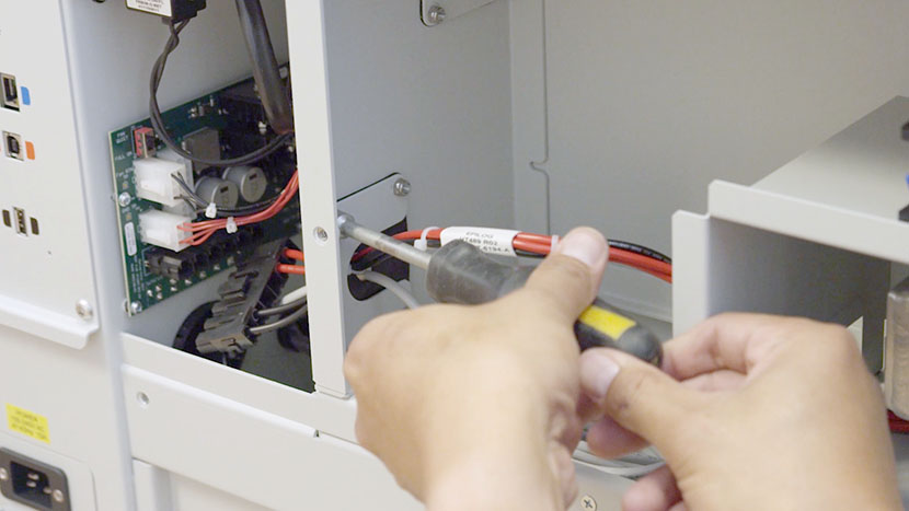
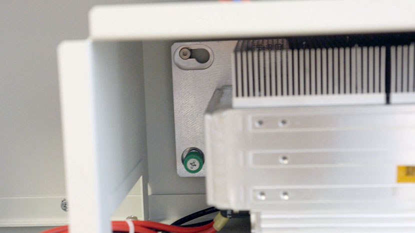
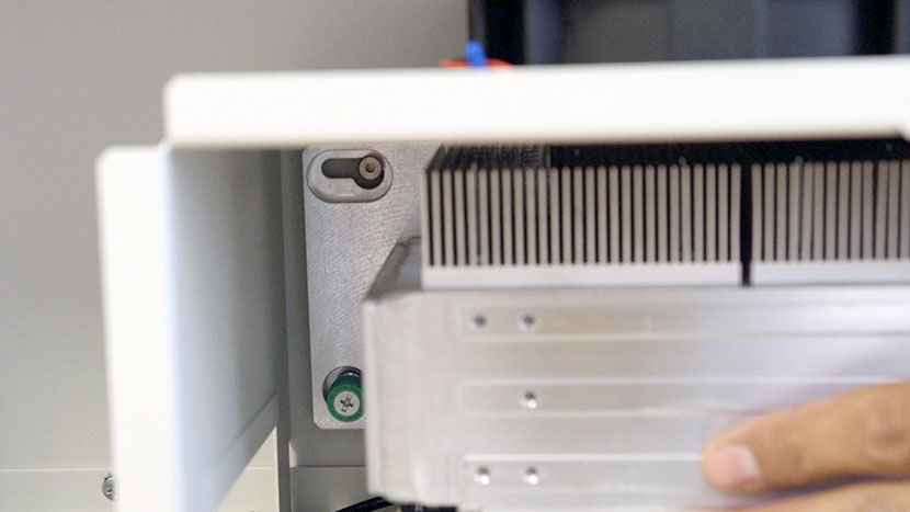
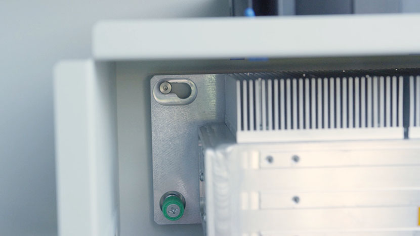
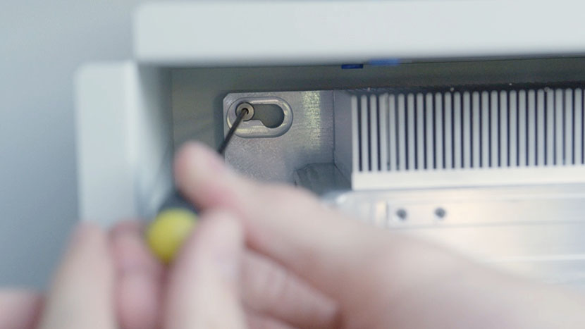
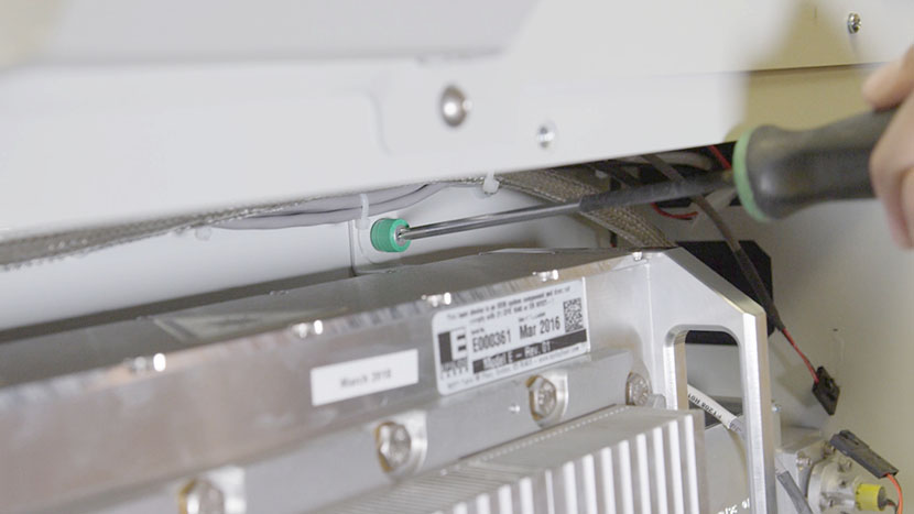
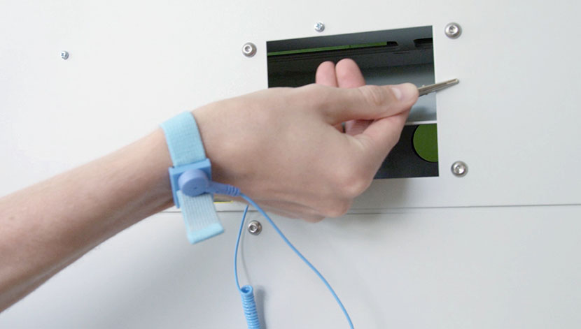
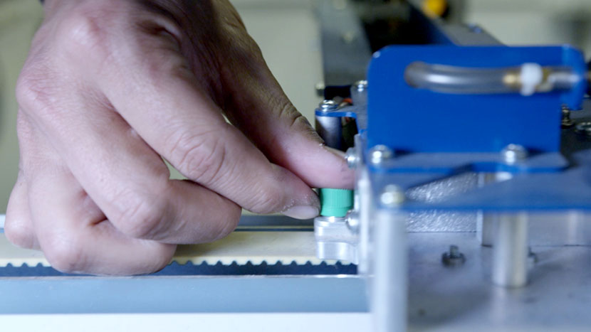
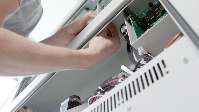
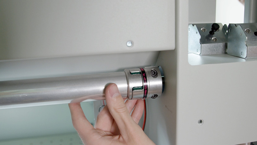
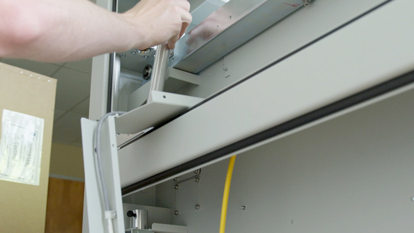
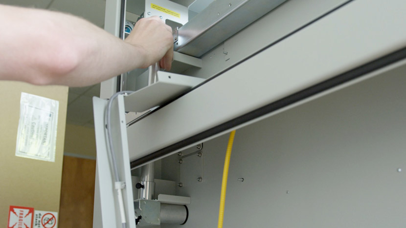
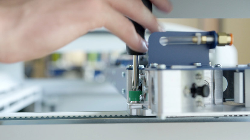
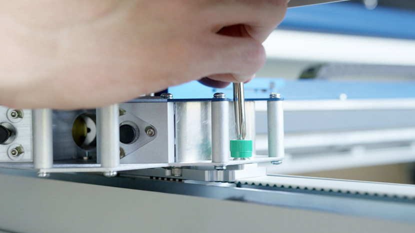
On both ends of the assembly, loosen the 2 green captive screws until they turn freely.

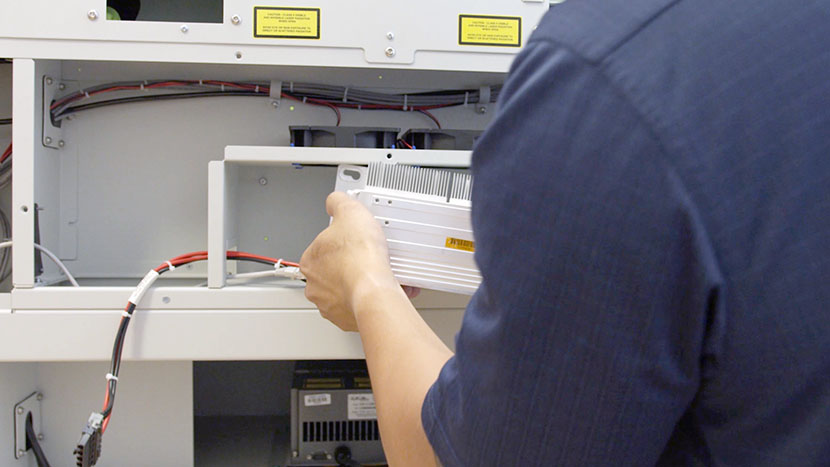
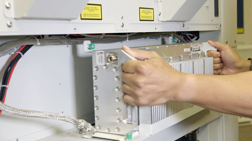
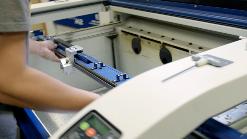
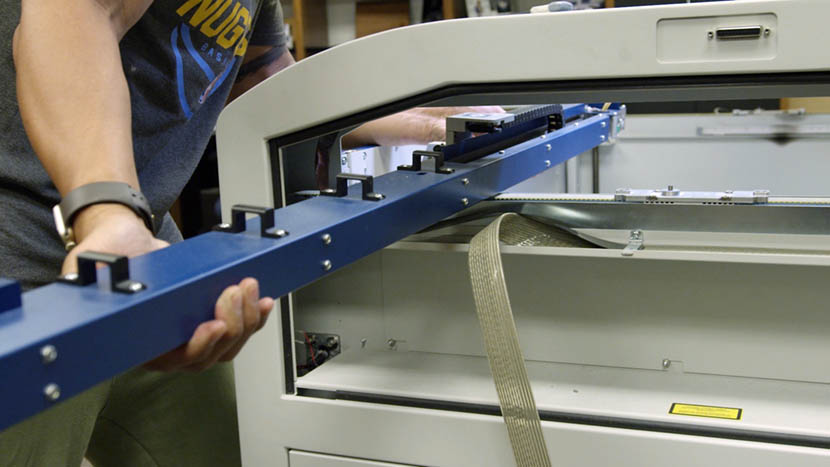
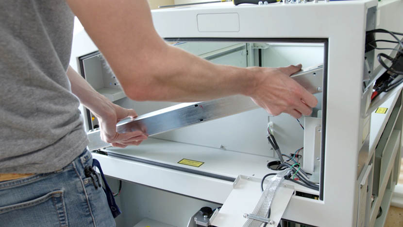
Now carefully lift the assembly from its mounted position and carry it out through the right side of the machine.
We will begin by replacing the right-side Y-Axis components. If you only need to replace the left-side components, skip ahead to Remove Additional Panels
Remove Old Right Y-Axis
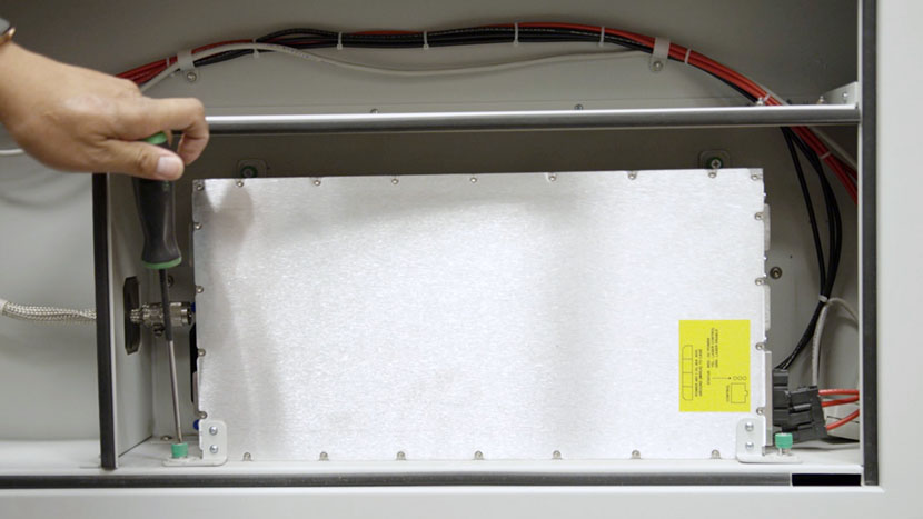
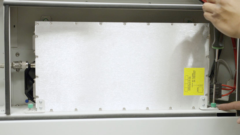
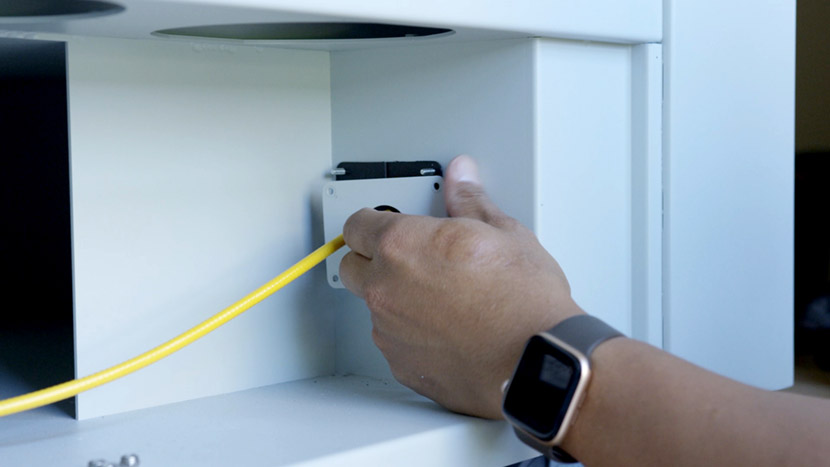
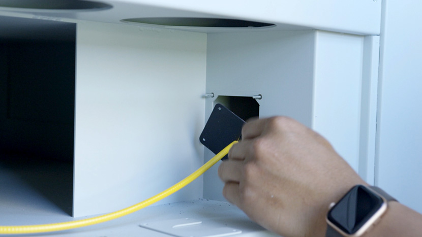
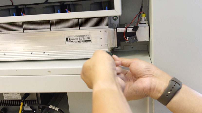
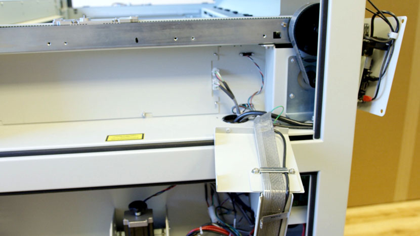
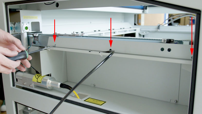
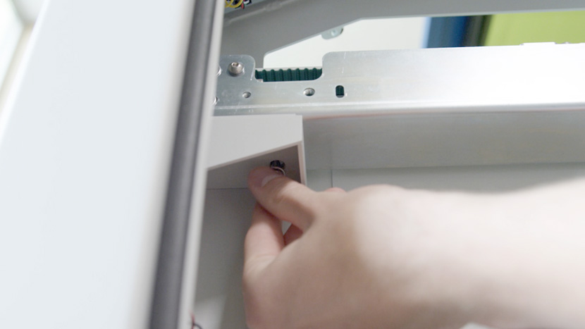
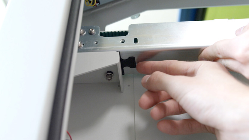
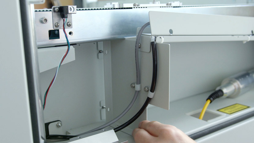
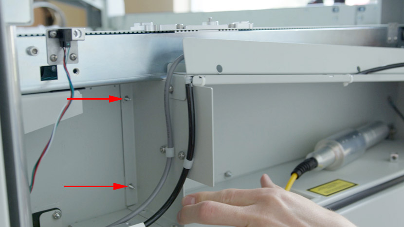
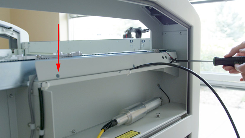
Use a nut driver to remove the 2 nuts securing the compartment panels on the interior side of the machine.
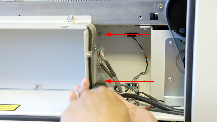
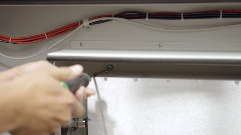
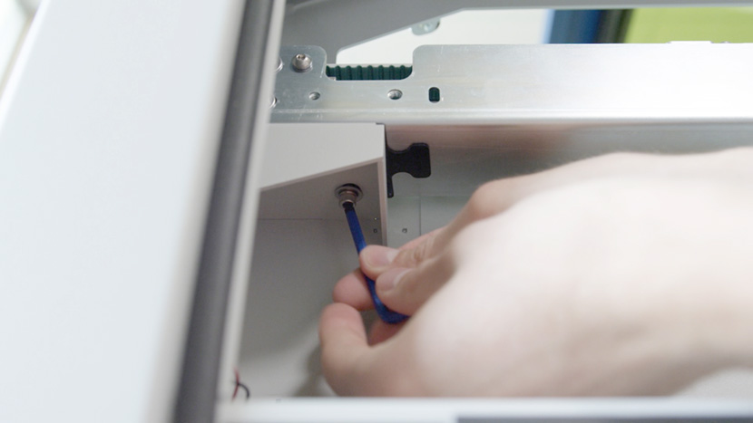
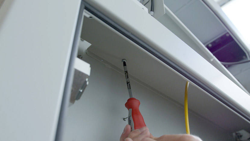
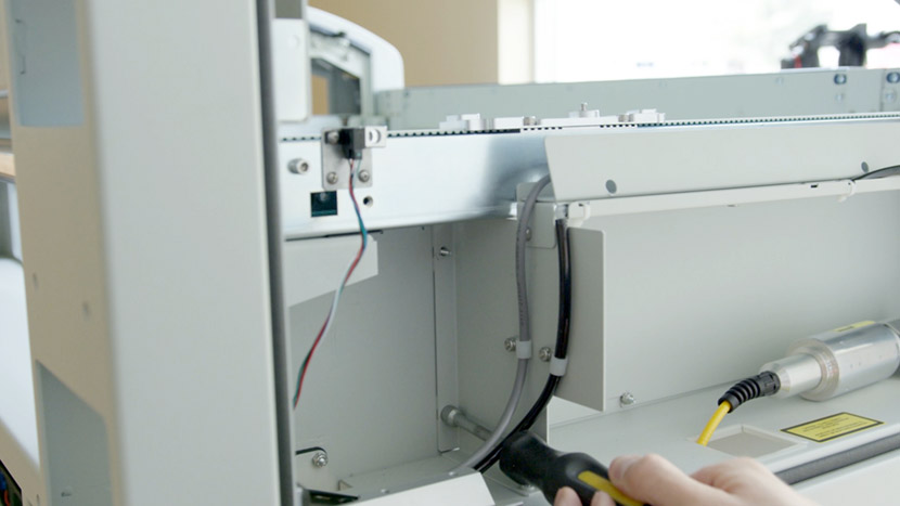
Use a Philips head screwdriver to remove the 3 screws securing the top of the compartment to the y-axis.
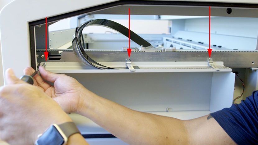
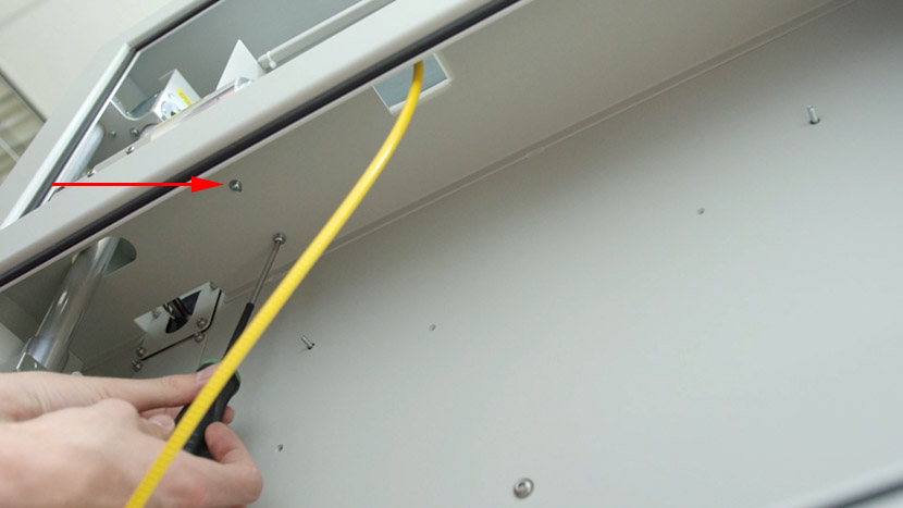
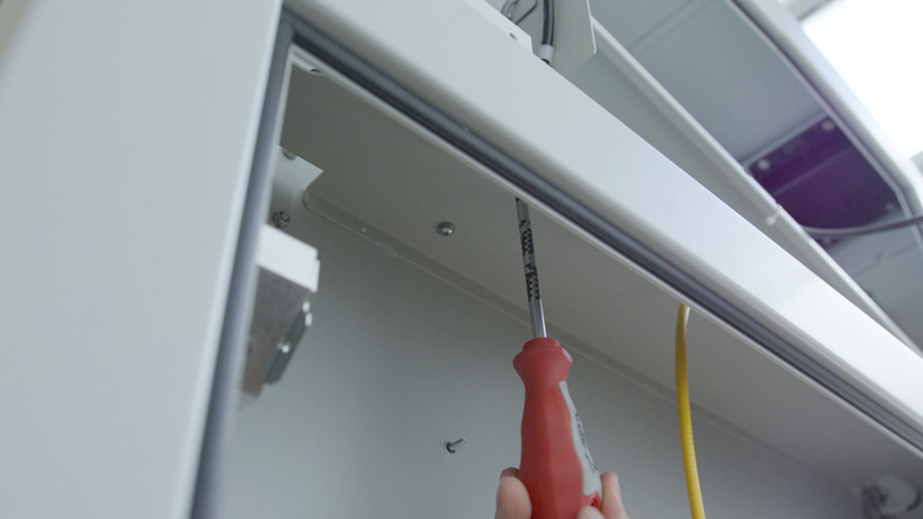
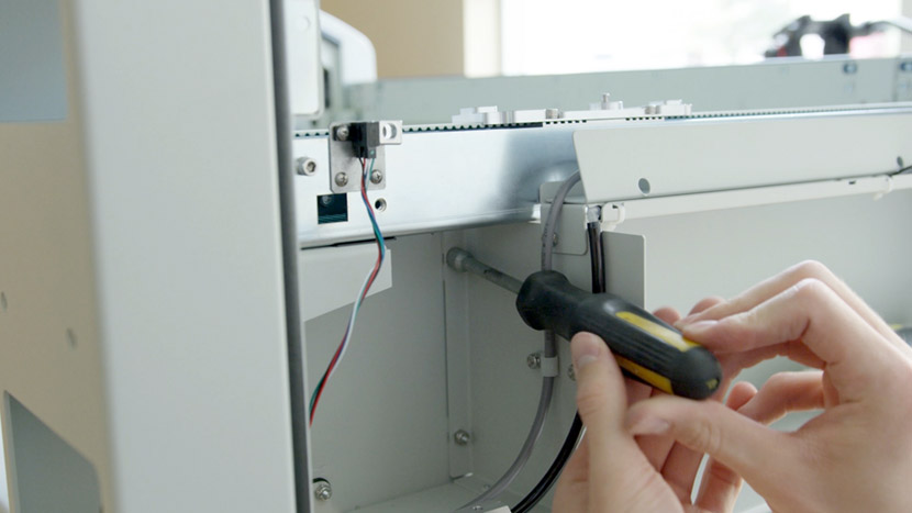
Then use a Philips head screwdriver to remove the 2 screws securing the compartment panels from underneath.
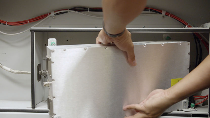
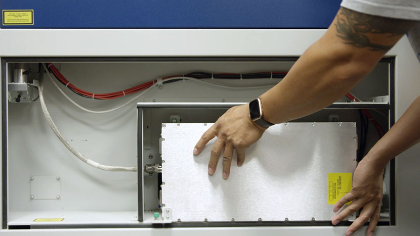
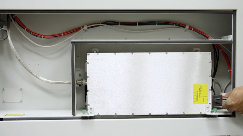
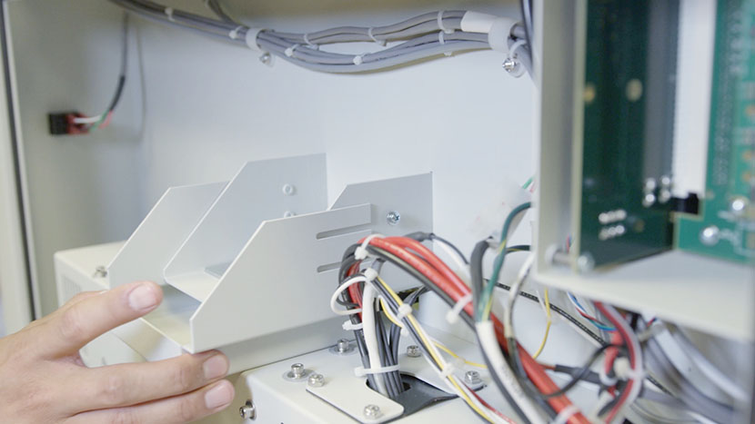
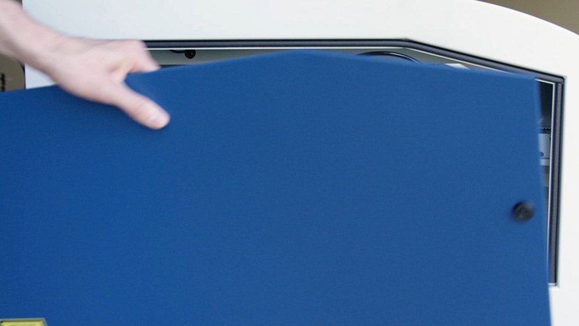
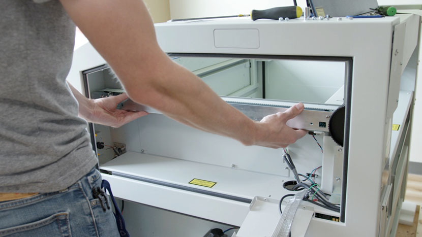
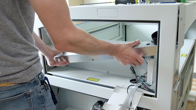
Gently pull out the compartment panels and let them rest, hanging off the side of the chassis.
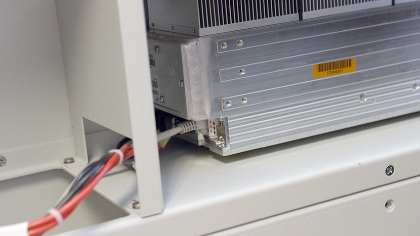
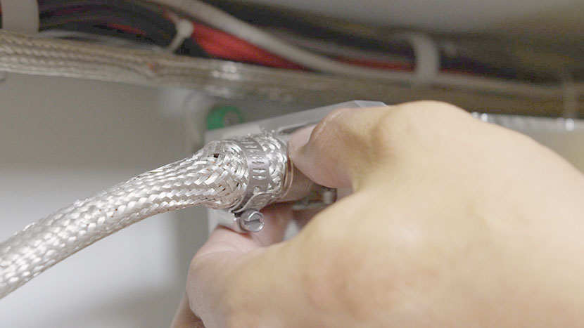
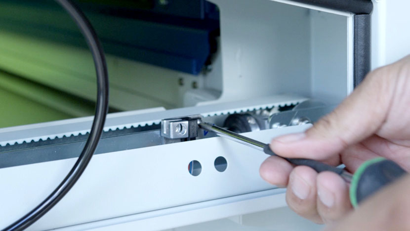
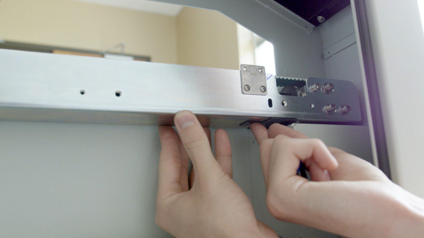
On the back side of the machine use a 5/32” hex key to loosen the 2 hex screws securing the axle clamp to the y-axis.

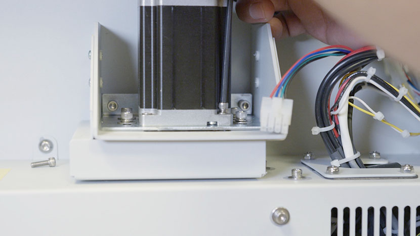
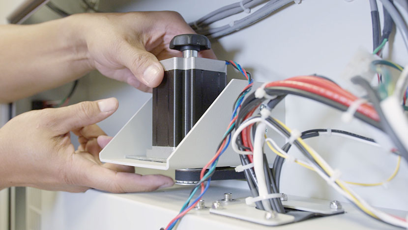
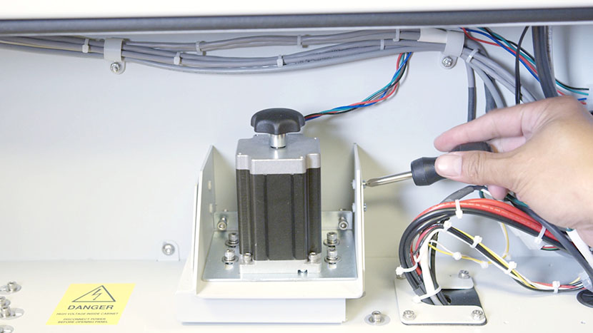
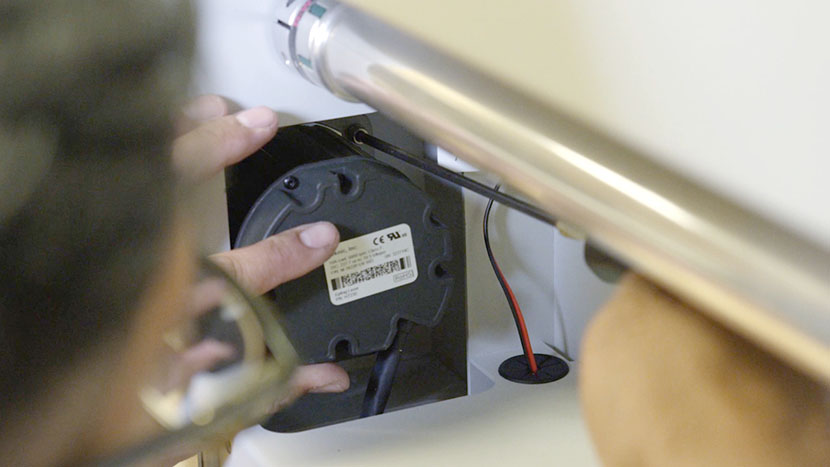
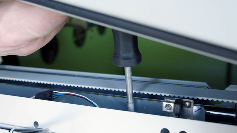
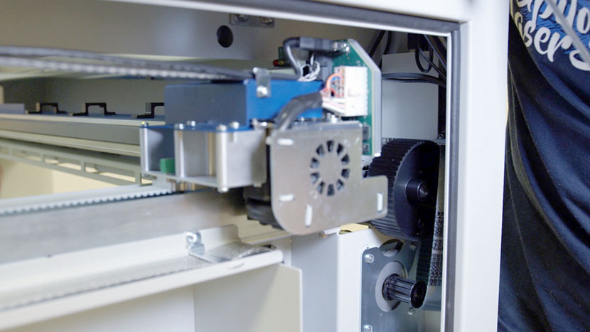
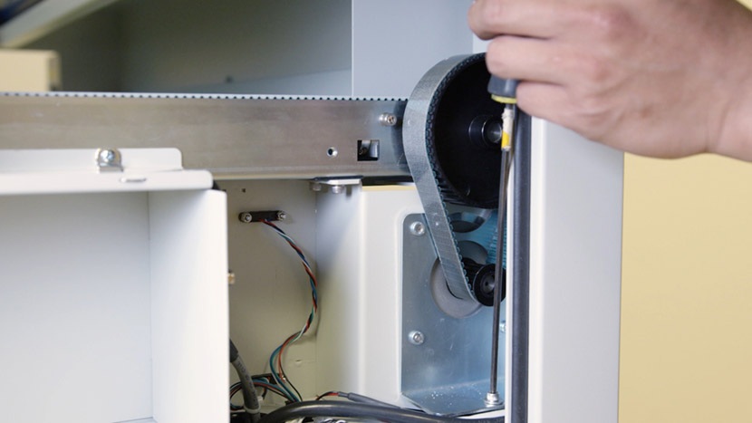
Use a 5/32” hex key to loosen but not remove the four mounting screws located at each corner of the y-motor.
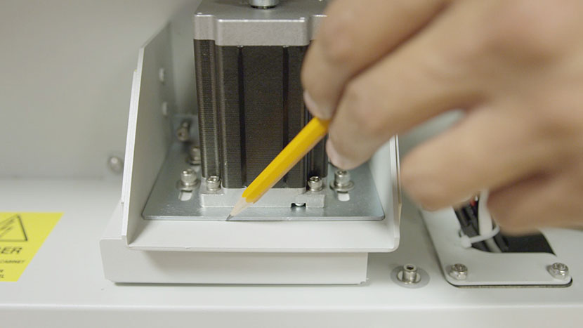
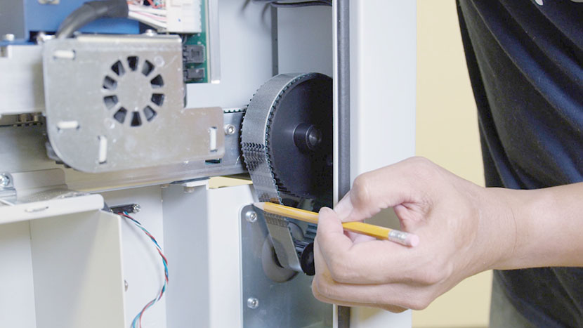
From the right-hand side of the machine use a pencil to mark the top of the y-motor mounting bracket. This will be used as a guide to return the mounting bracket to the correct position later.
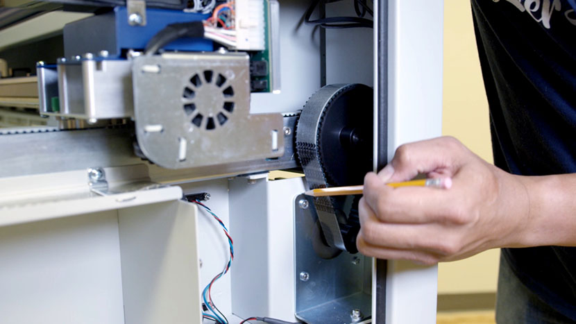
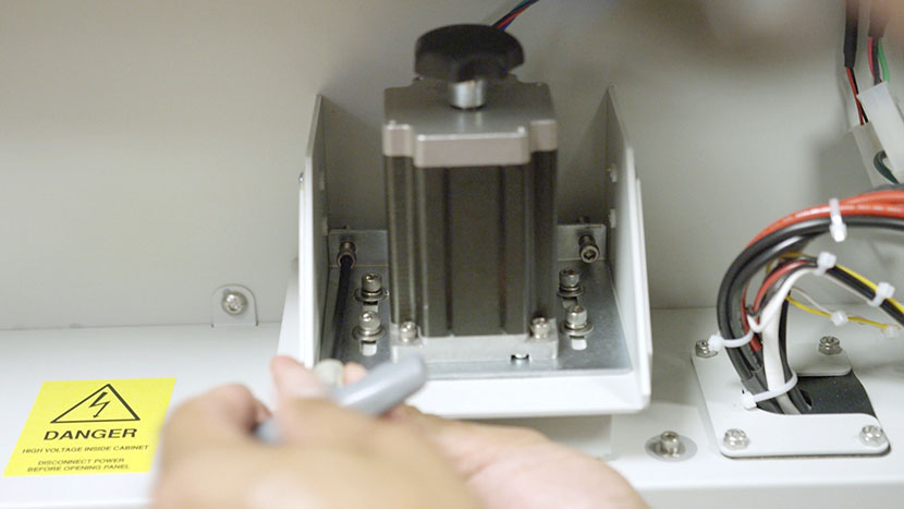
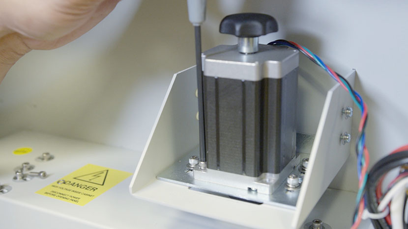
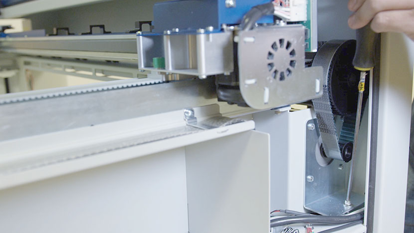
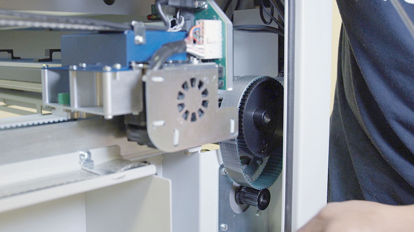
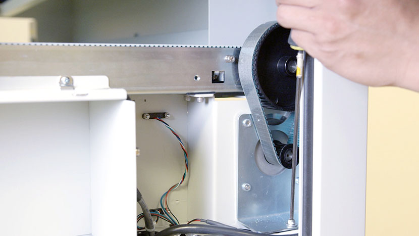
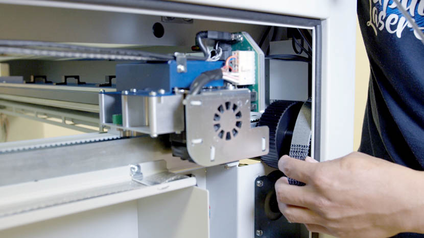
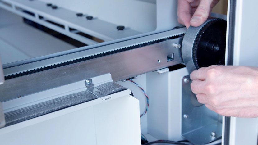
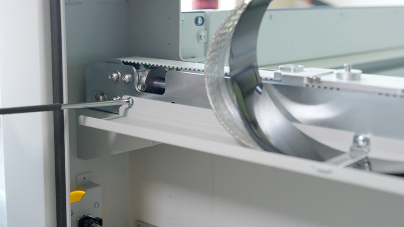
Use a 5/32” hex key to loosen the y-motor tensioning screw. This will loosen the y-axis reducer drive belt.
Remove the reducer drive belt from the y-motor pulley.
Use a 5/32” hex key to remove the two hex keys securing the y-axis to the chassis near the back of the machine.
Remove the black plastic shim underneath the y-axis.
Then remove the two hex screws securing the y-axis to the chassis near the front of the machine.
Remove the black plastic shim.
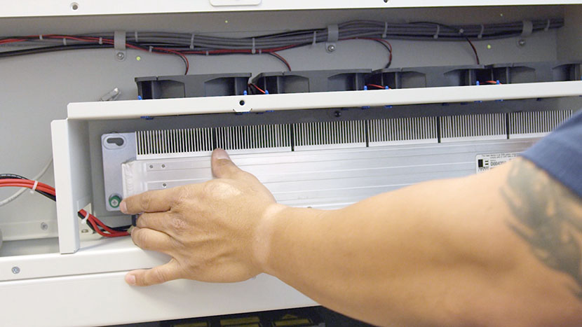
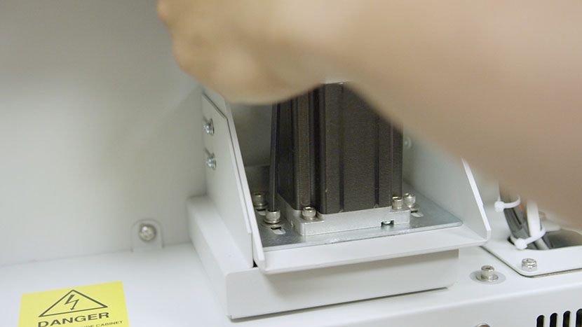
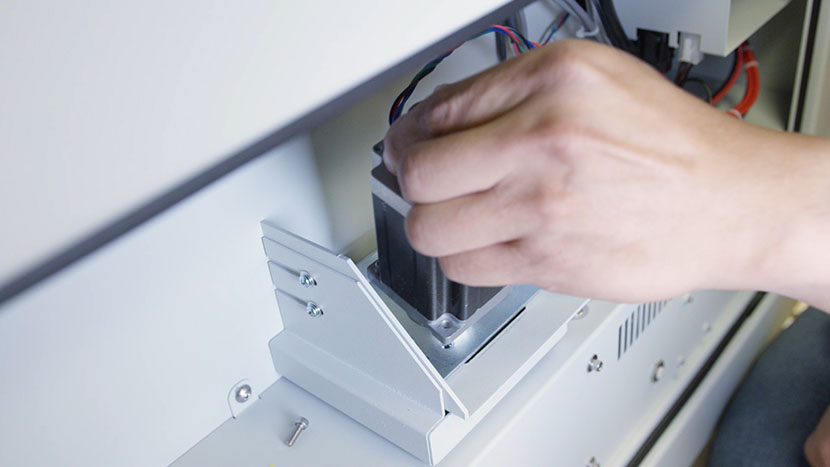
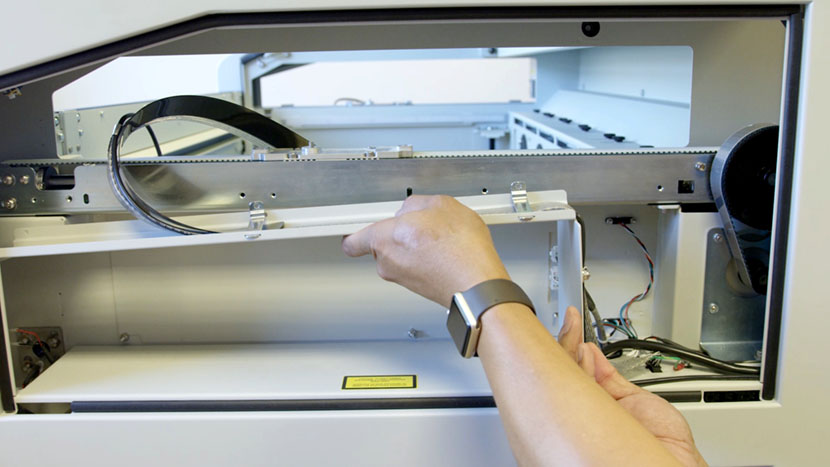
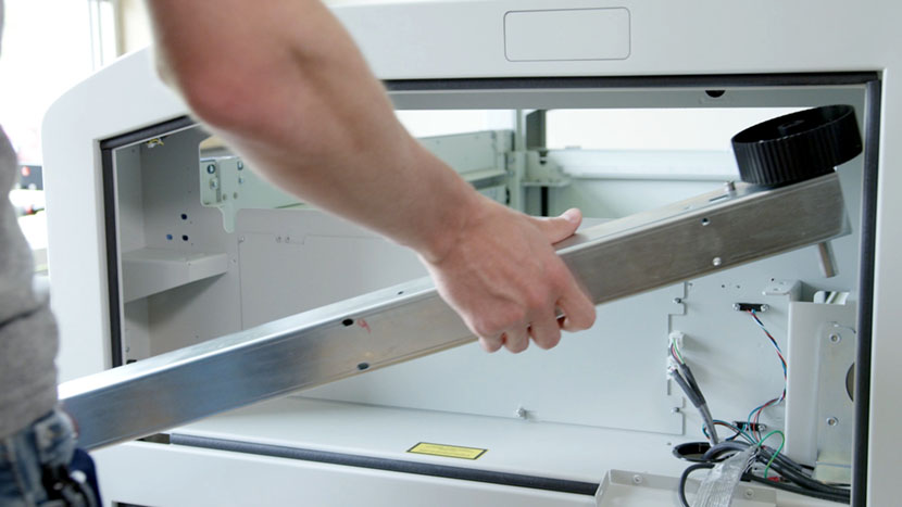
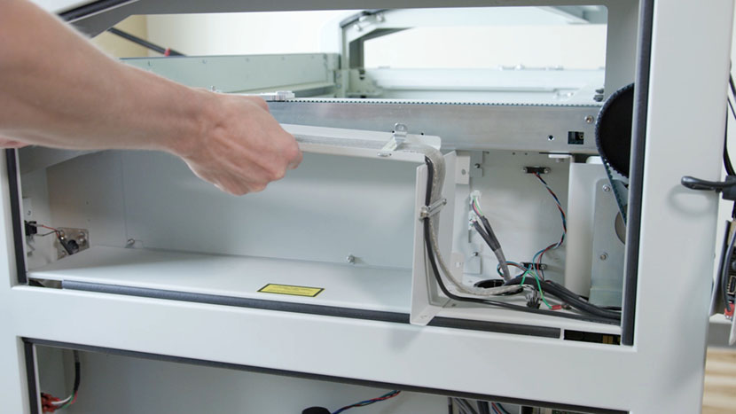
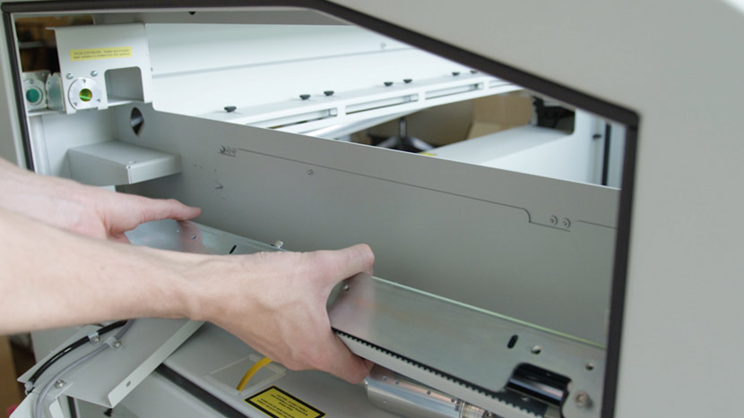
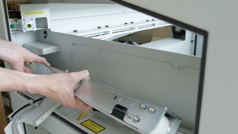
Now remove the y-axis. Carefully lift it, turning it 90 degrees inward while lifting the back up and leaning the front down.
Push it slightly out the back through the open corner panel, then pull the entire axis out through the side of the compartment

Install New Right Y-Axis
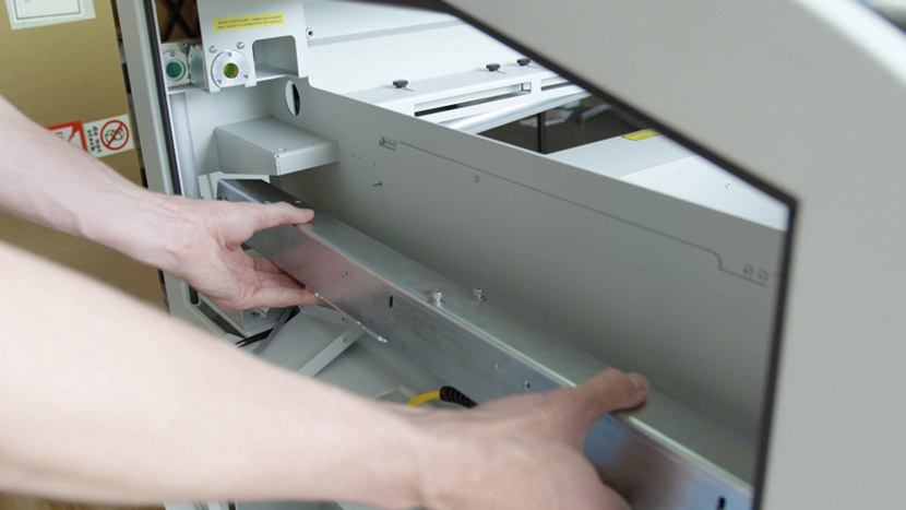
To install the new y-axis begin by holding it so the wheel is positioned on top.
Slide it in through the side of the compartment, pushing the back end with the wheel out through the top corner panel on the back of the machine.
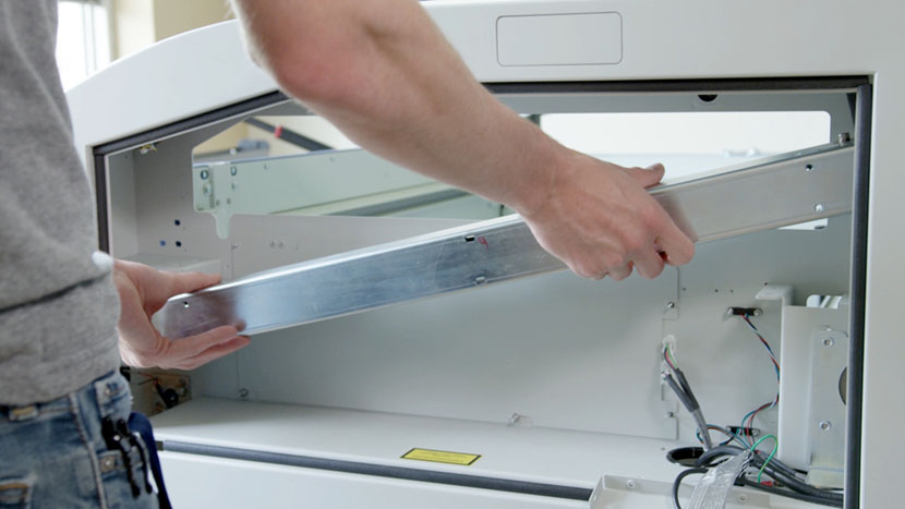
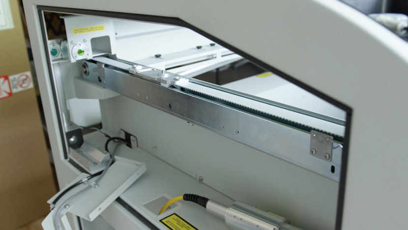
When the front end is within the chassis, straighten it out then turn the axis 90 degrees outward and rest it on its mounting brackets.
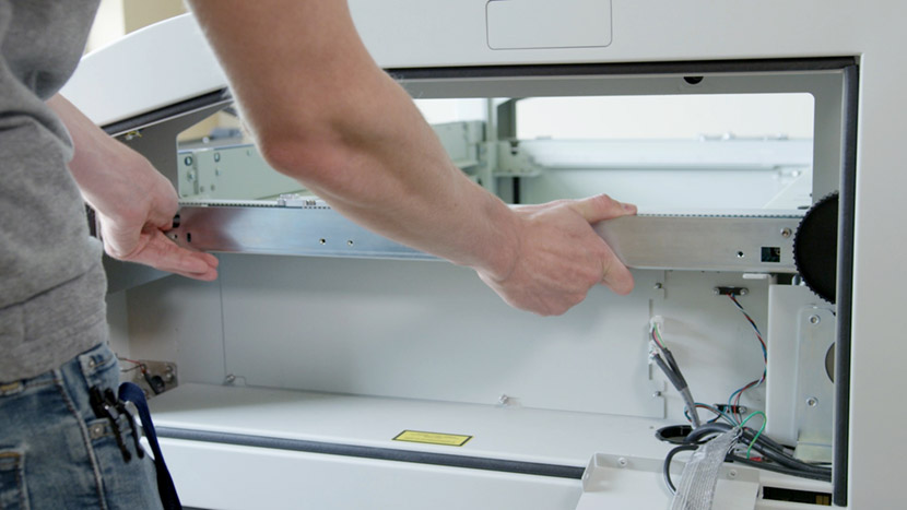
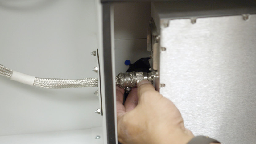
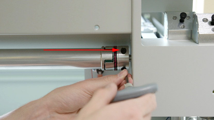
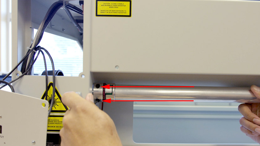
Insert the y-axis drive axle into the rear axle clamp.
Secure the front of the y-axis to its mounting bracket by using a 5/32” hex key to insert the two hex screws halfway so that the y-axis can still be lifted slightly.

Lift the y-axis and insert the black plastic shim, then tighten the 2 hex screws.
Secure the back of the y-axis to its mounting bracket the same way, using a 5/32” hex key to insert the 2 hex screws halfway.
Insert the black plastic shim, then tighten the 2 hex screws.

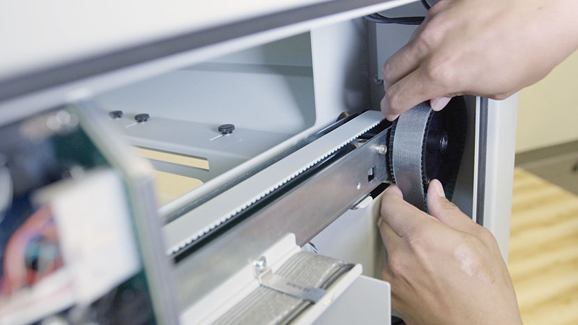
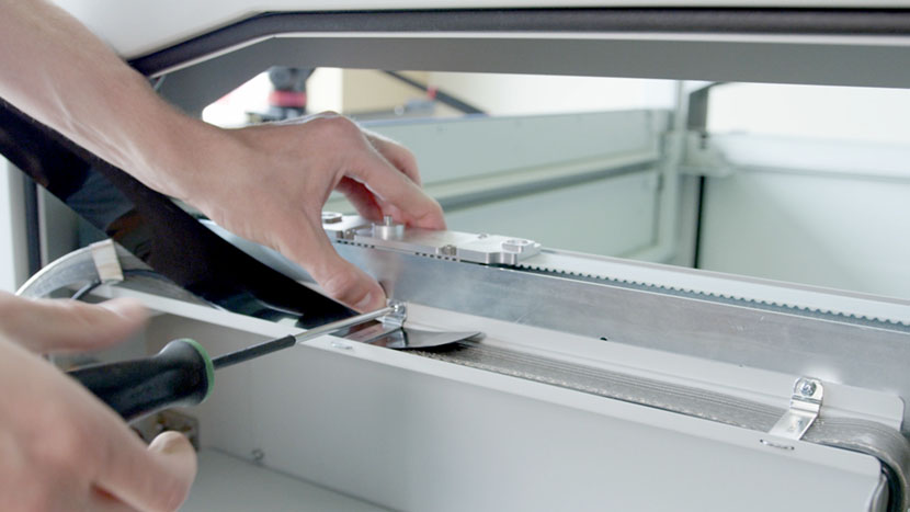
Slide the drive belt onto the two wheels.
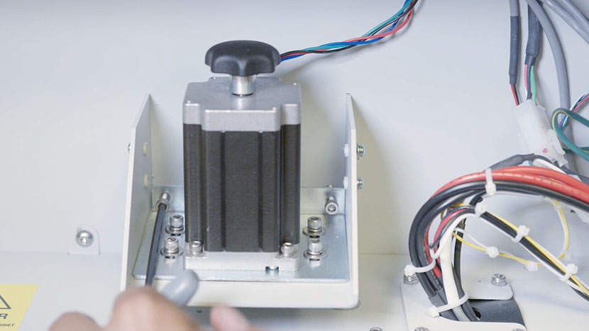
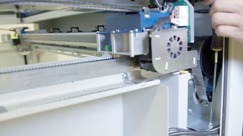
Tighten the y-motor tensioning screw until the pencil mark you made earlier is visible.
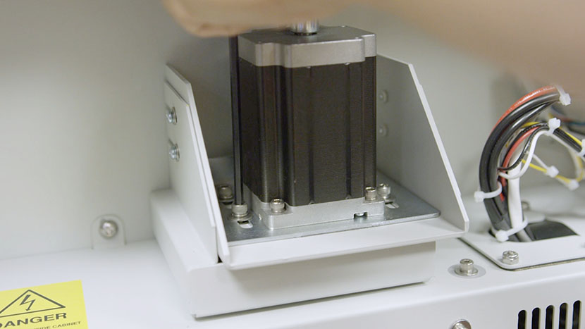
Now tighten the 4 mounting screws.
Now lift the compartment panels and slide them back into place over the two mounting screws on the interior side of the compartment.
Insert the two Philips head screws from underneath.
Then use a Philips head screwdriver to insert the 3 screws that connect the compartment panels to the side of the y axis. Two of the screws will also go through and secure the wire harness clamps.
We will now replace the left-side Y-Axis components. If you do not need to do this, skip ahead to Align and Clamp
Remove Additional Panels
Now we’ll replace the y-axis on the left side of the machine.
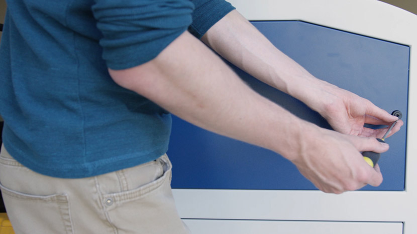
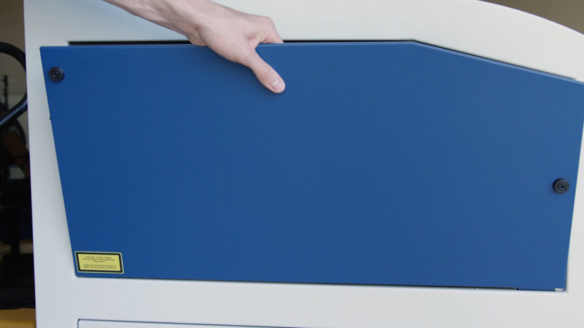
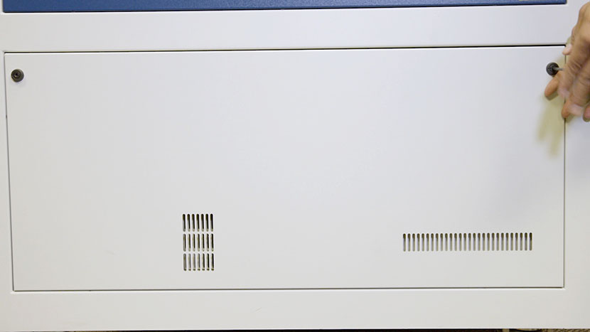
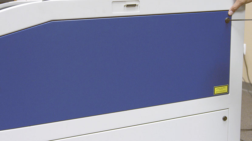
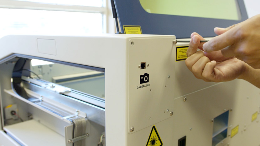
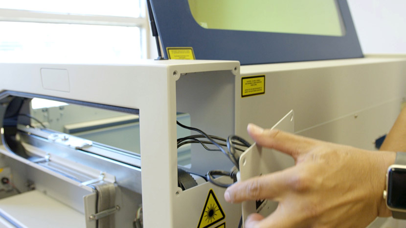
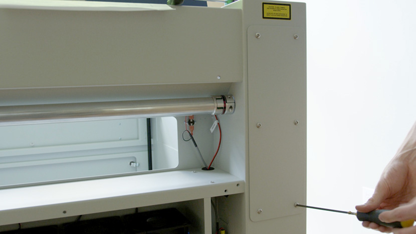
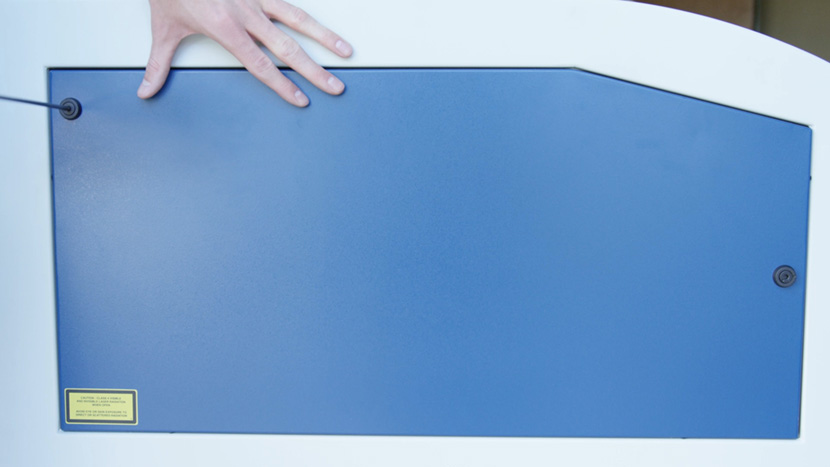
Use a 5/32” hex key to remove the bottom access panel on the left side of the machine.
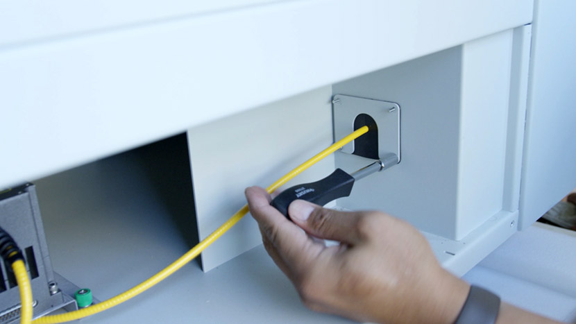
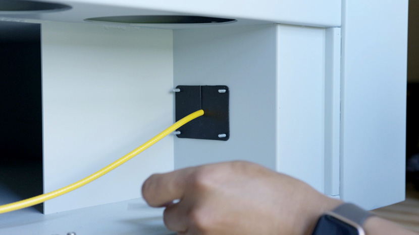
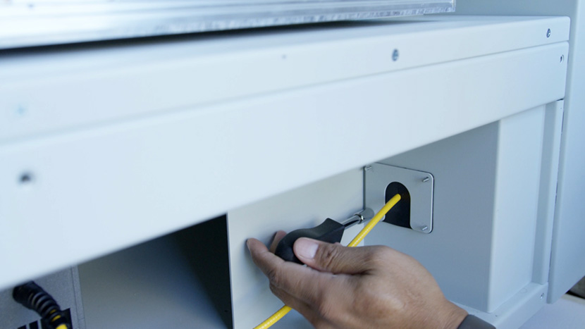
Then, while facing the back of the machine, remove the small panel on the right, near the edge.
Remove Old Left Y-Axis
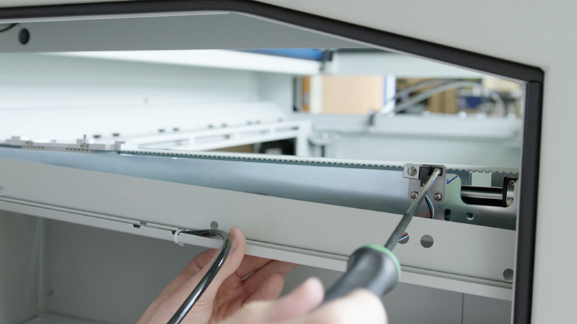
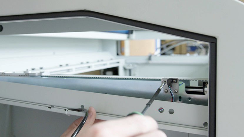
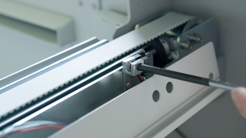
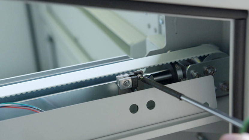
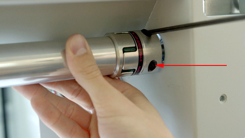
Use a 5/32” hex key to loosen the 2 hex screws securing the axle clamp on the back of the machine.
Then use a Philips head screwdriver to remove the 3 screws securing the compartment panels to the y-axis.
Use a Philips head screwdriver to remove the 2 screws securing the compartment panels from underneath.
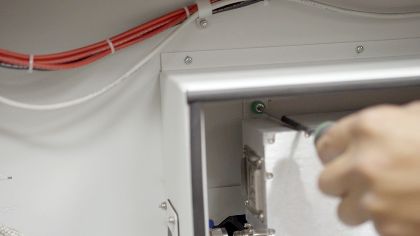
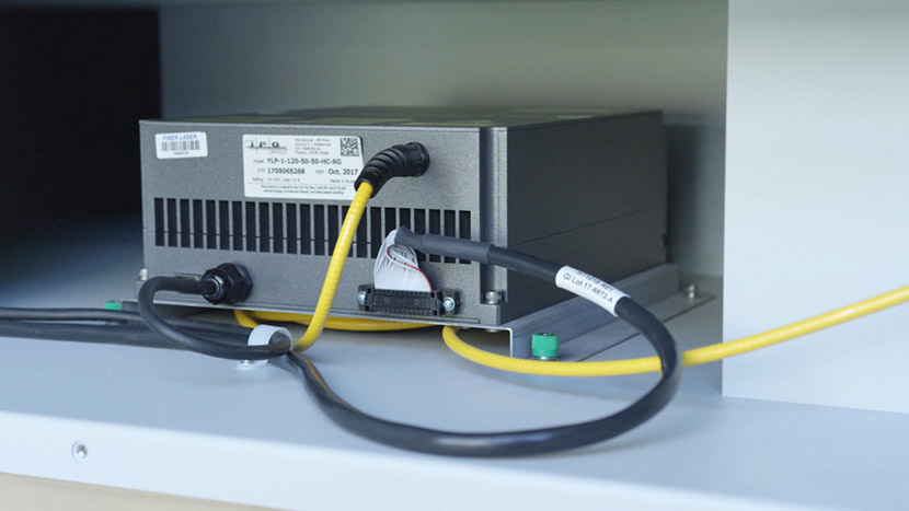
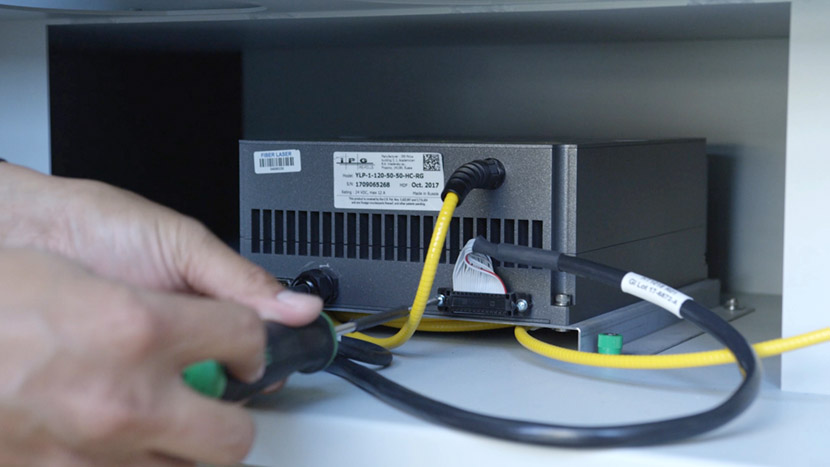
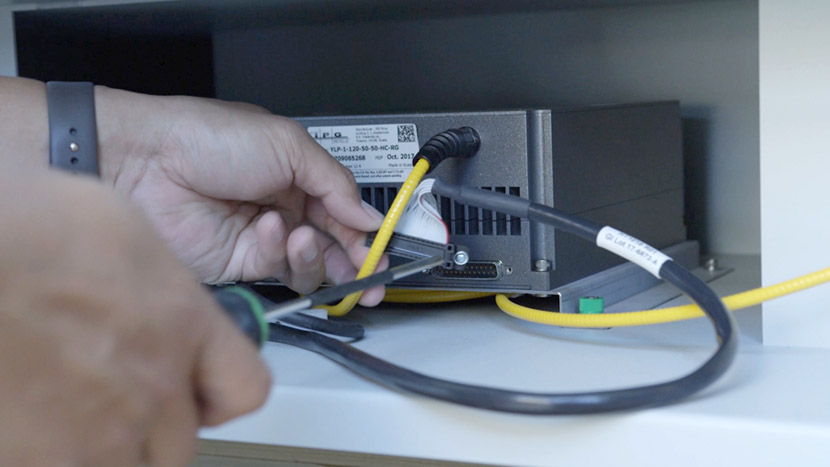
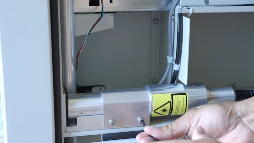
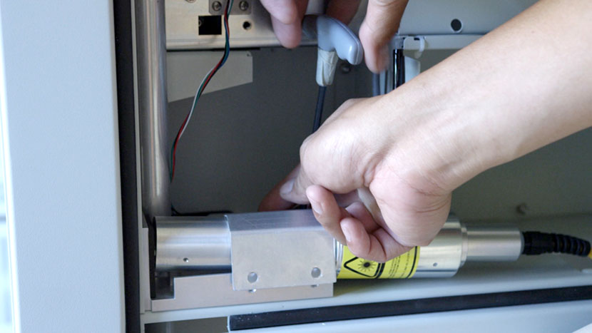
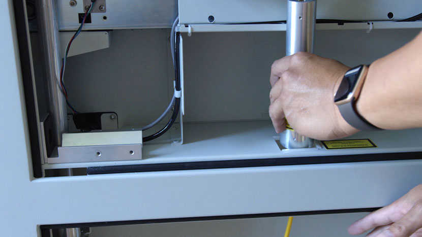
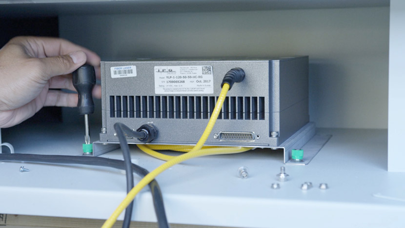
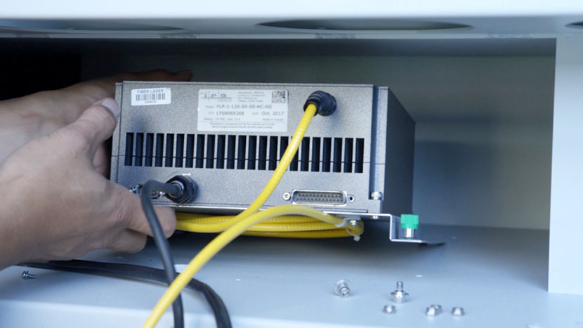
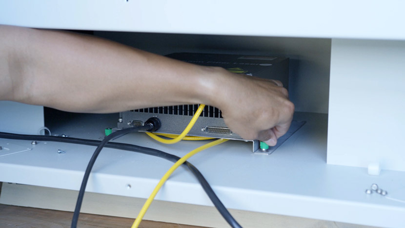
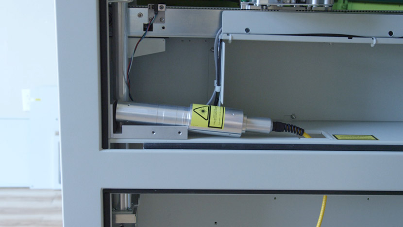
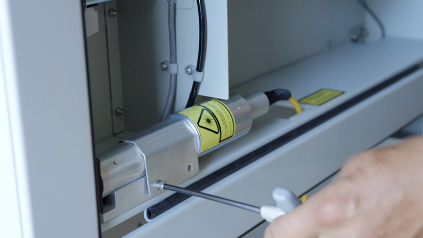
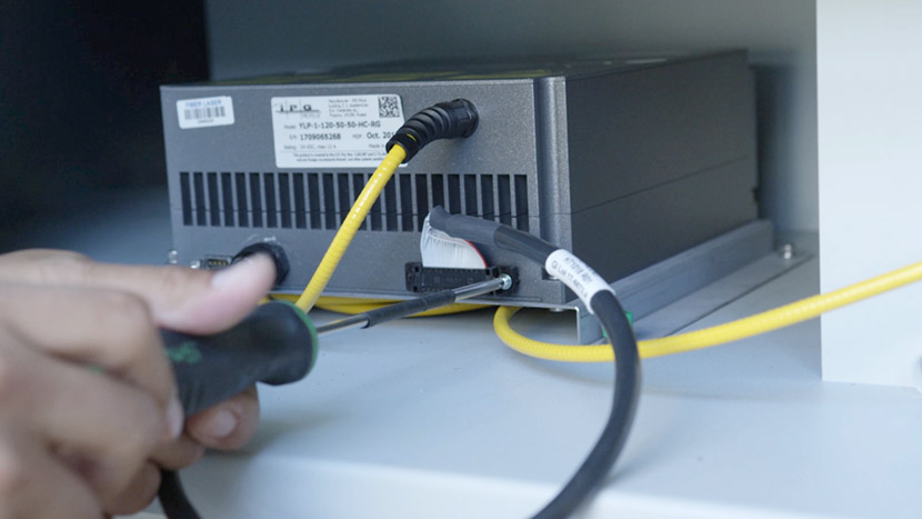
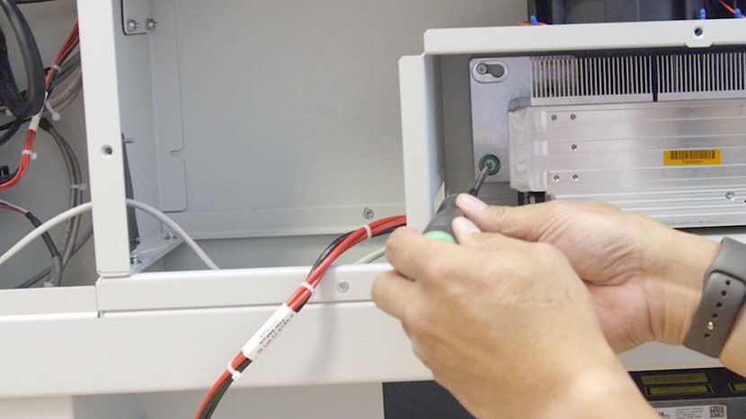
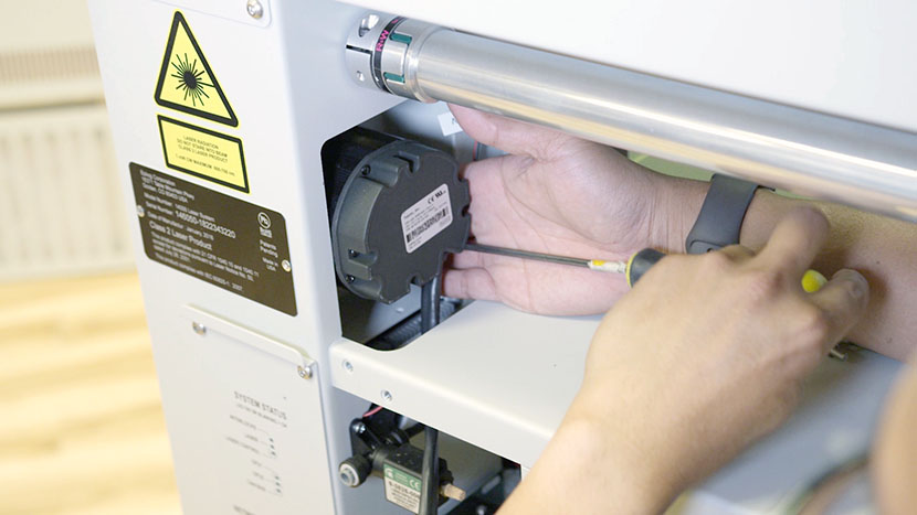
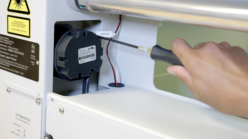
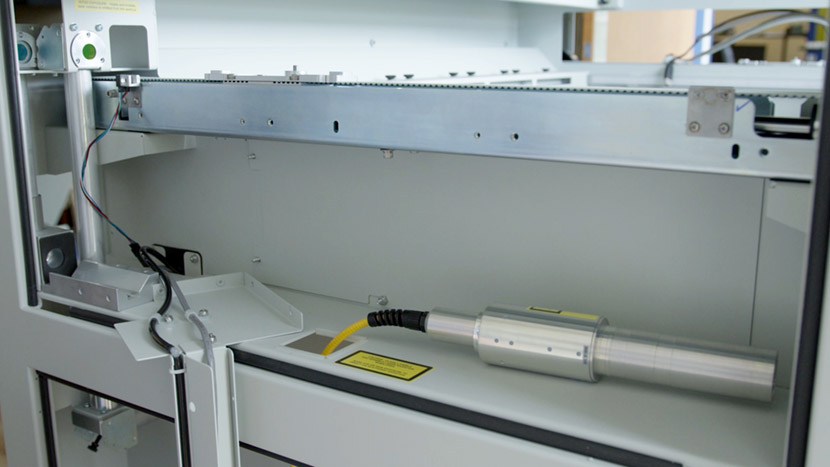
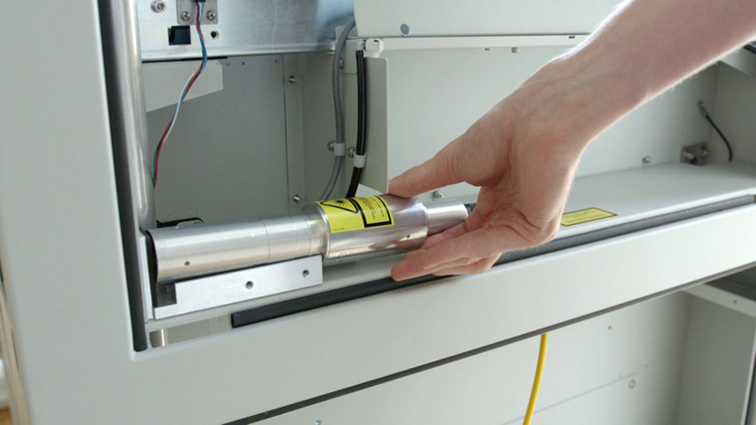
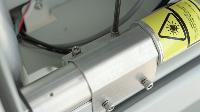
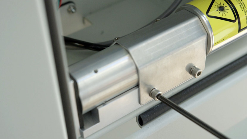
If your Fusion M2 is equipped with a fiber laser source, you will need to remove the fiber laser head to provide clearance for the compartment panels to be removed. Use a 5/32” hex key to remove the 4 hex screws securing the laser head clamp.

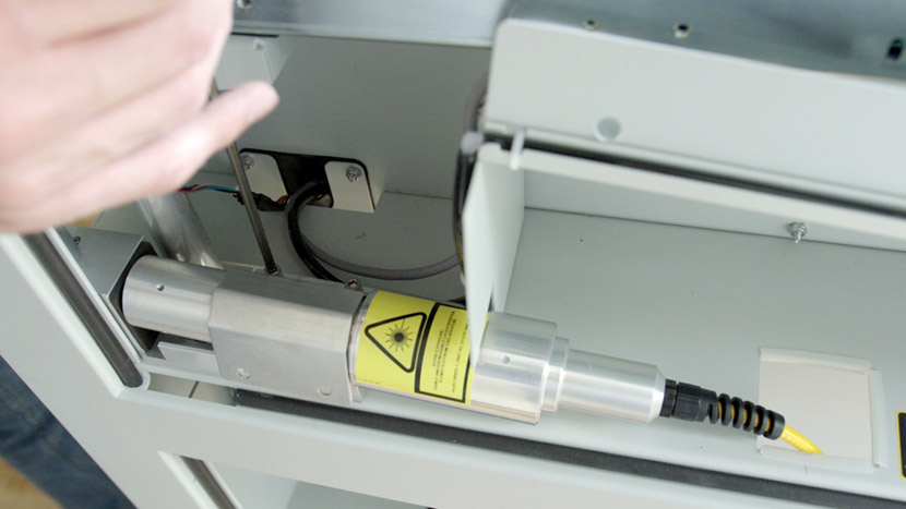
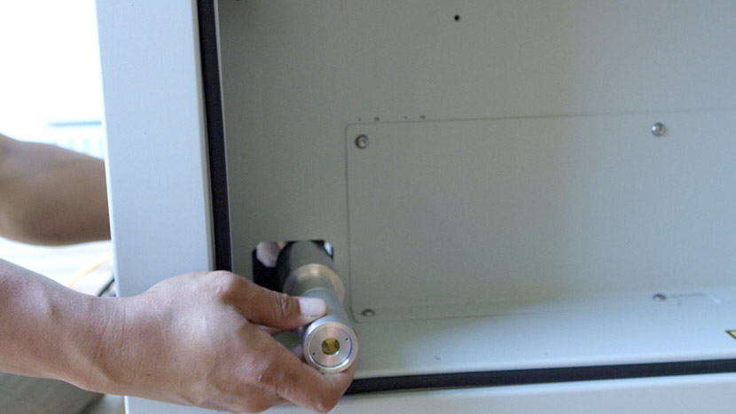
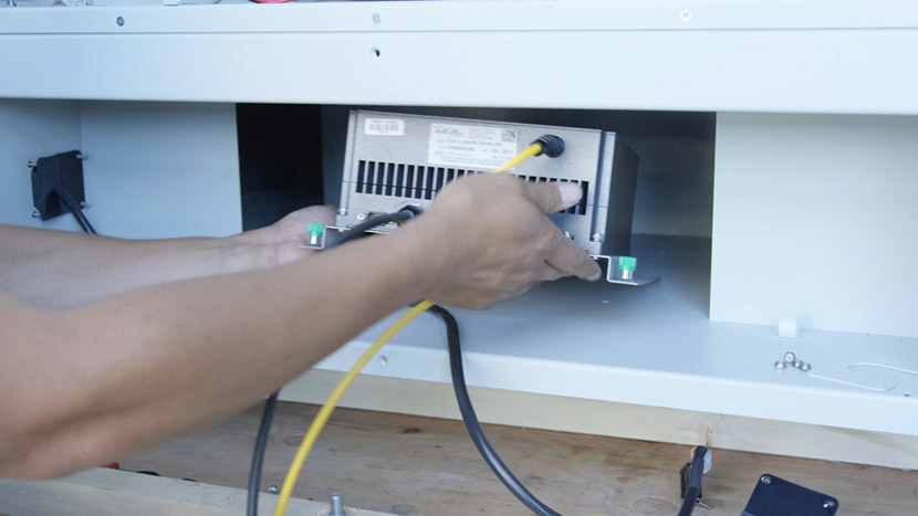
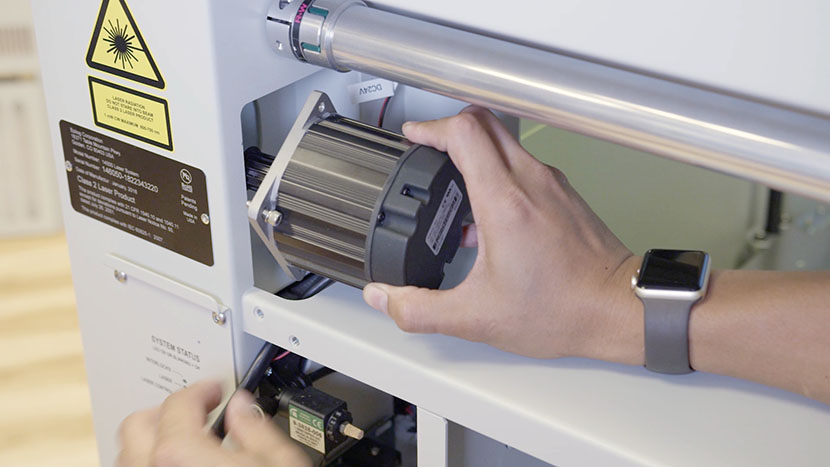
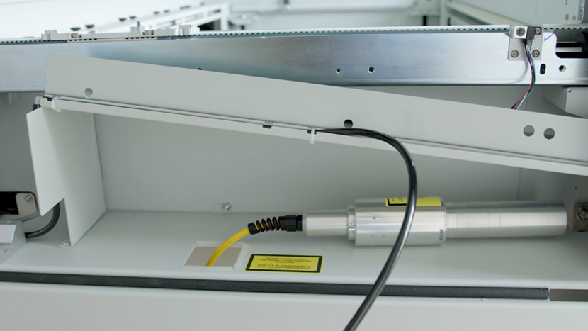
Set the laser head to the side so it’s out of the path of the compartment panels.
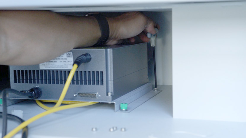
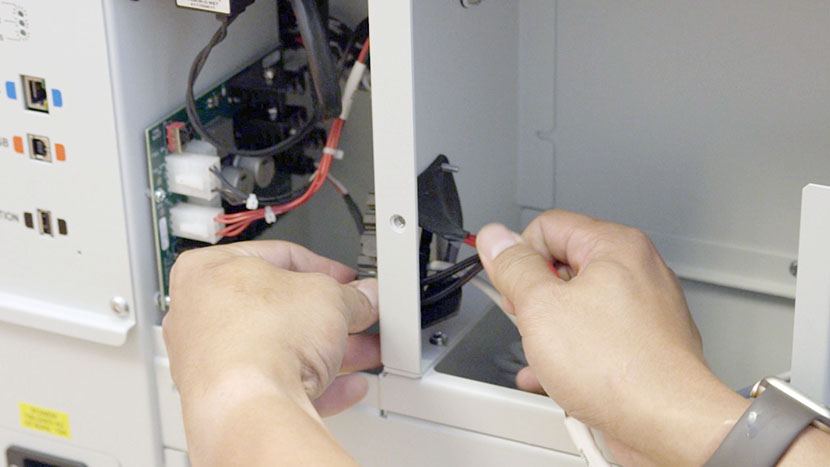
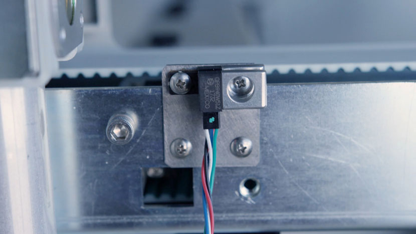
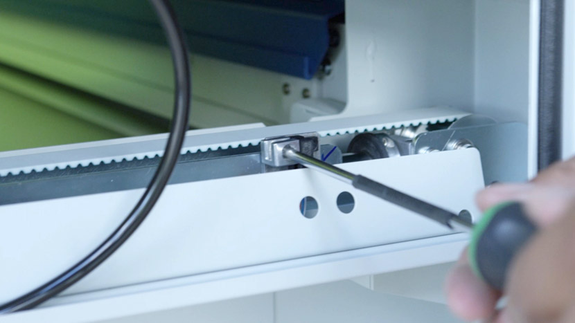
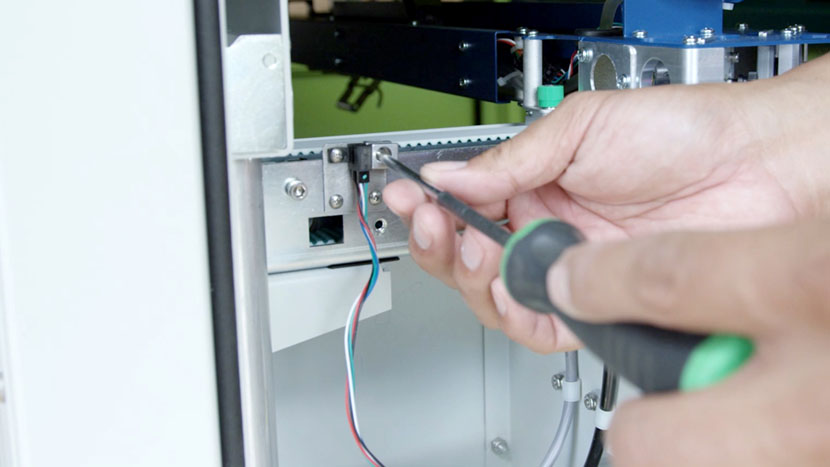
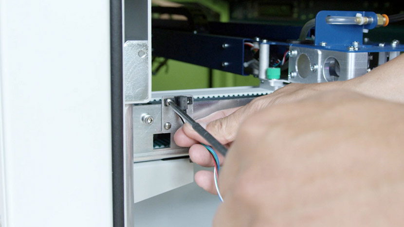
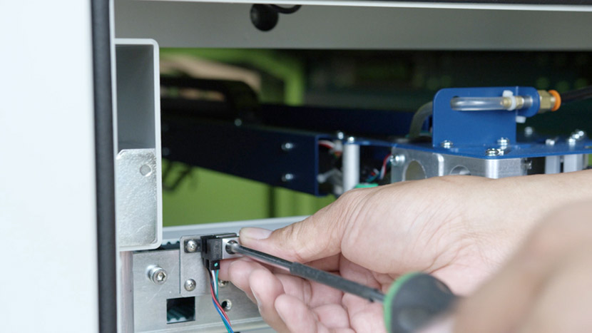
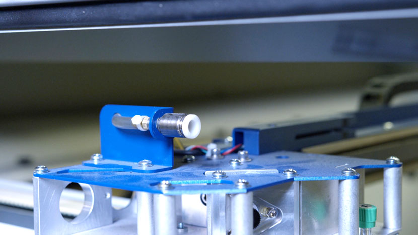
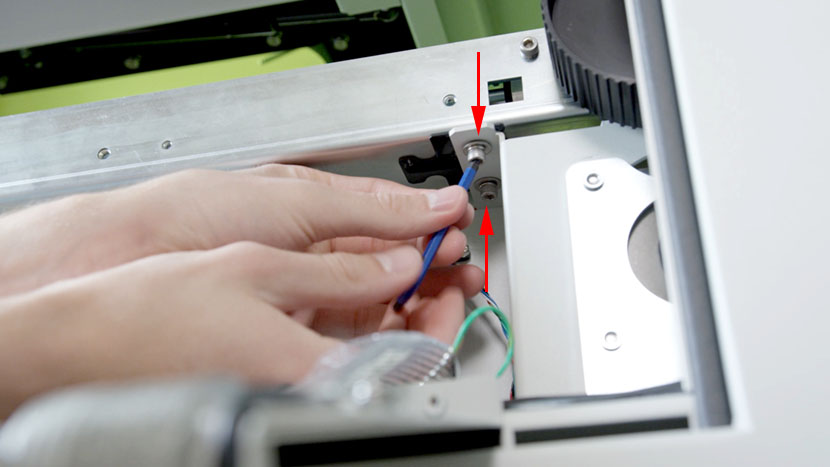
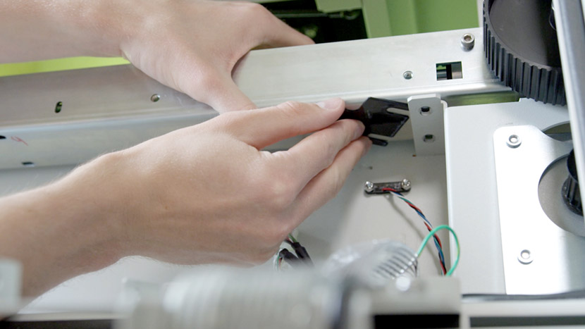
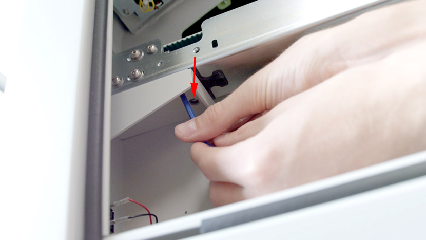
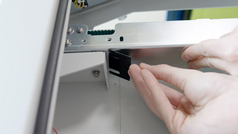
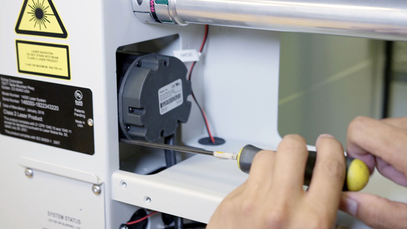
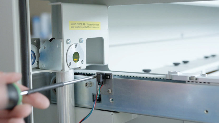
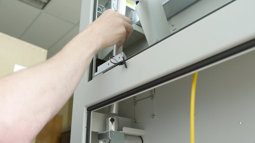
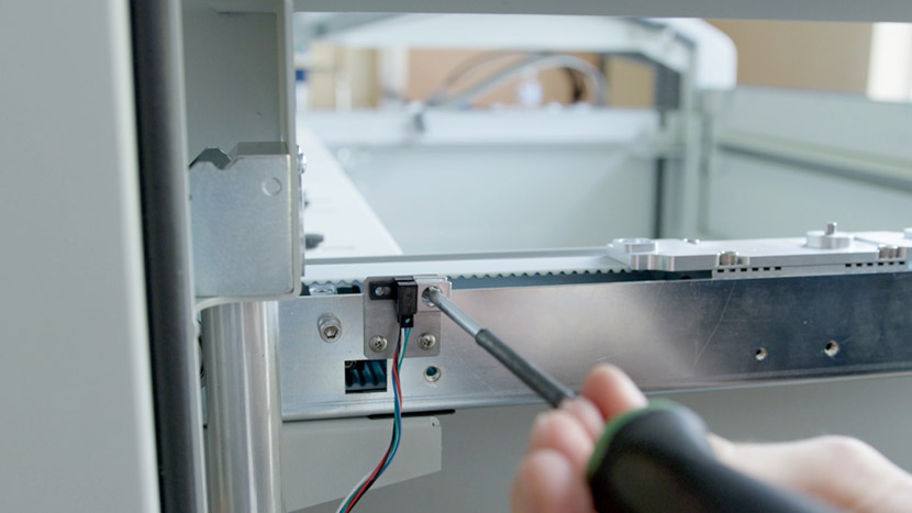
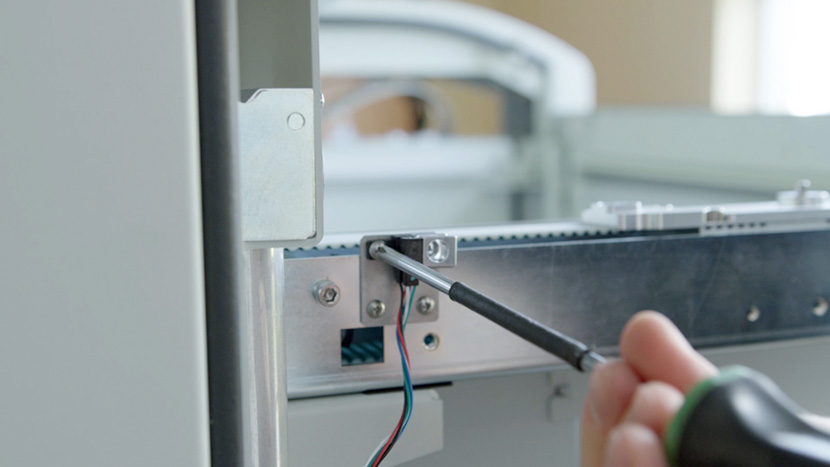
Use a Philips head screwdriver to remove the 2 screws securing the front sensor to the y-axis.
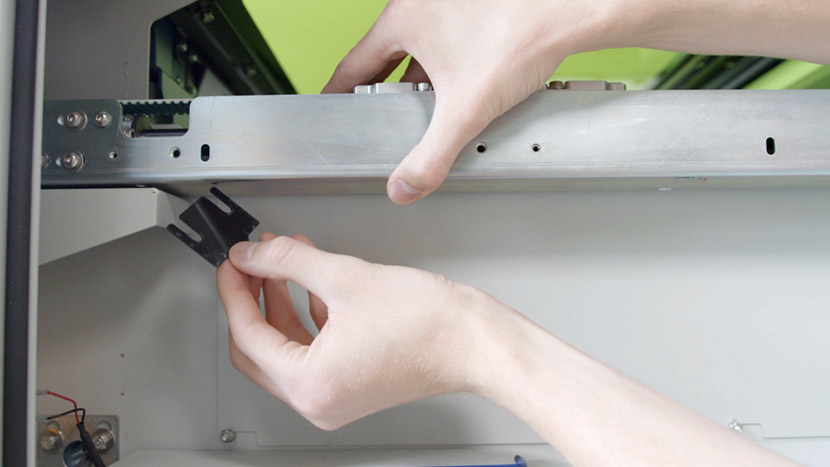
Set the small metal switch guard to the side.
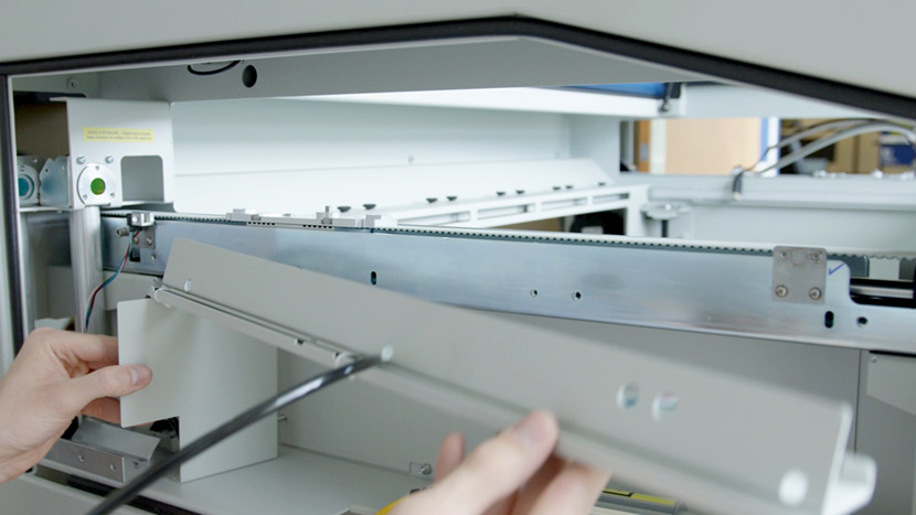
Gently pull out the compartment panels and let them rest, hanging off the side of the chassis.
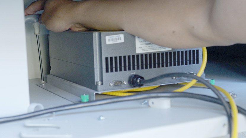
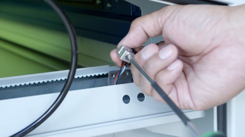
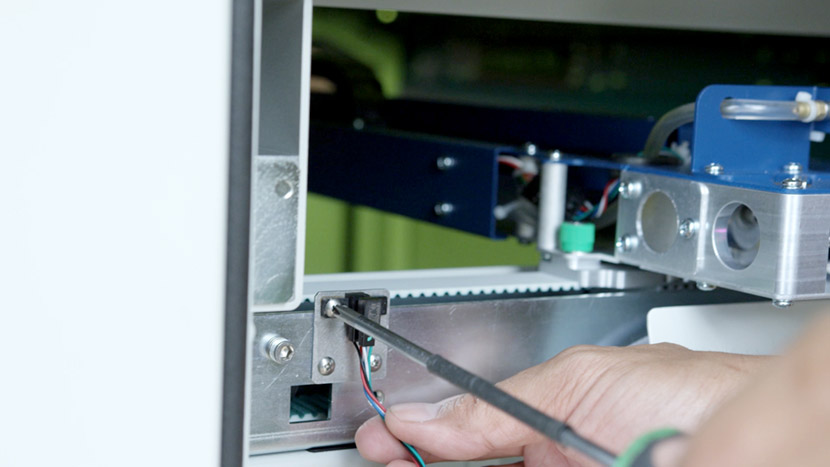
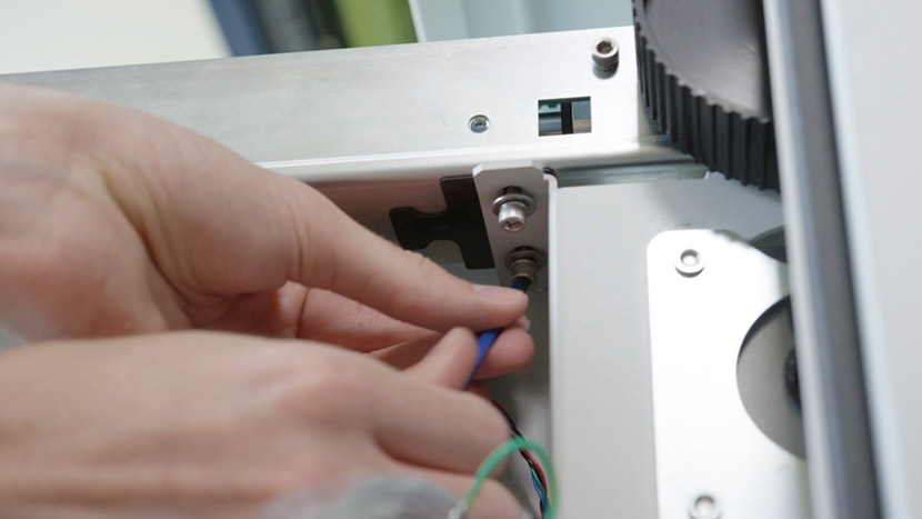
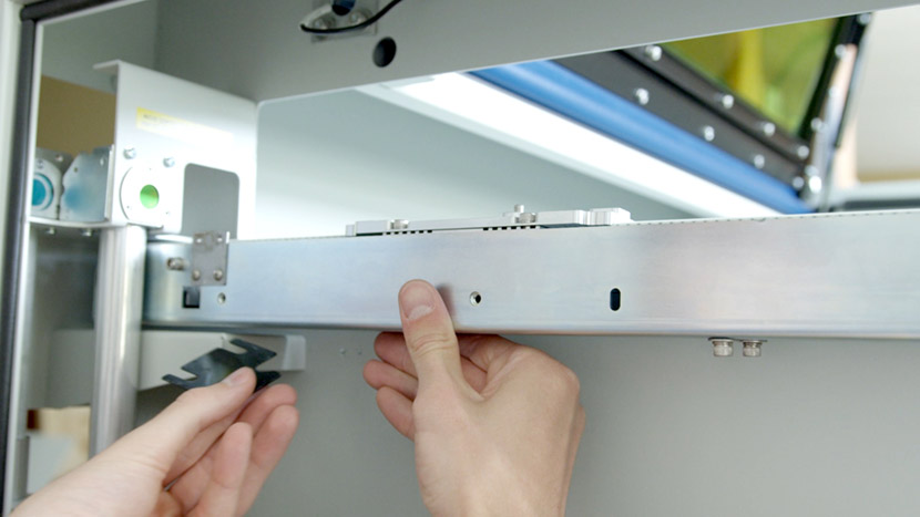
Use a Philips head screwdriver to remove the 2 screws securing the rear sensor to the y-axis.

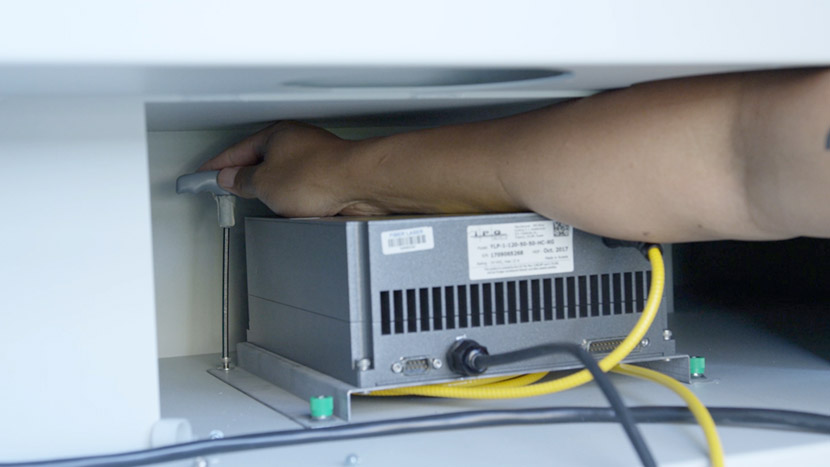
Use a 5/32” hex key to remove the 2 hex screws securing the y-axis to the chassis near the back of the machine.
Remove the black plastic shim.
Then remove the 2 hex screws securing the y-axis to the chassis near the front of the machine.
Remove the black plastic shim.
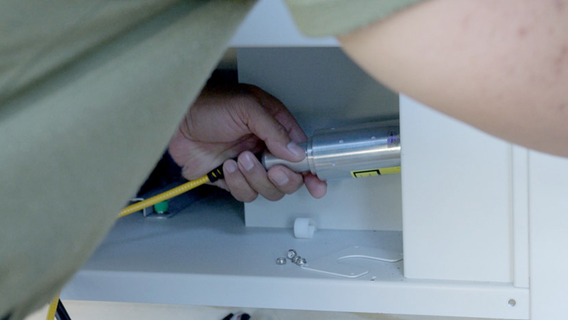
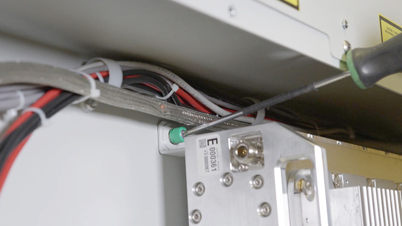
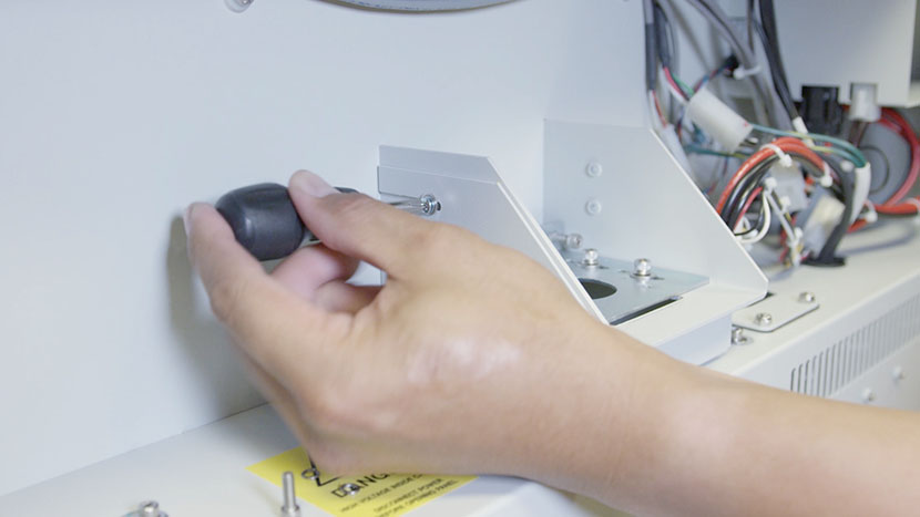
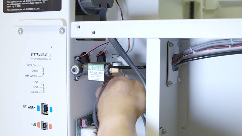
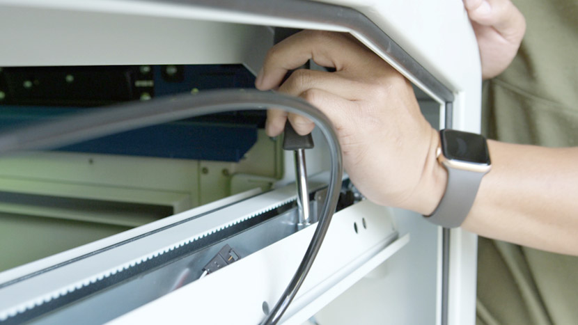
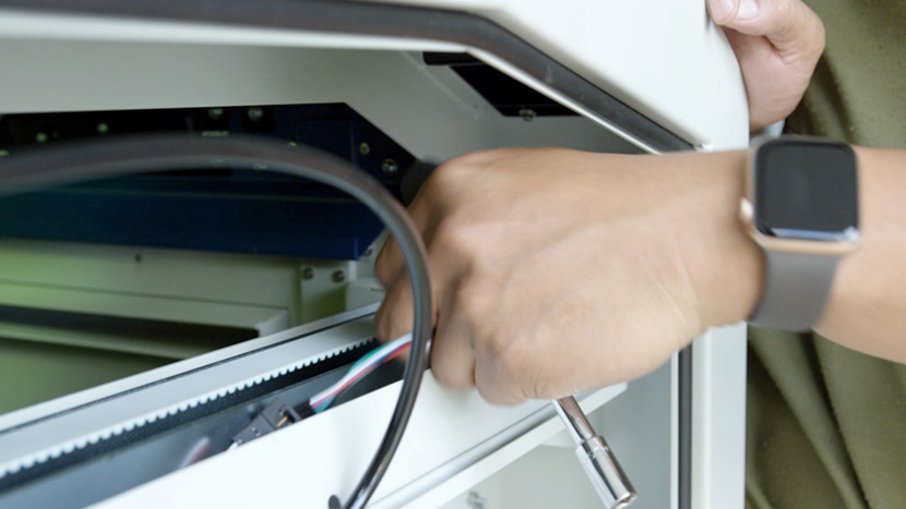
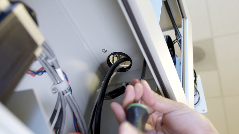
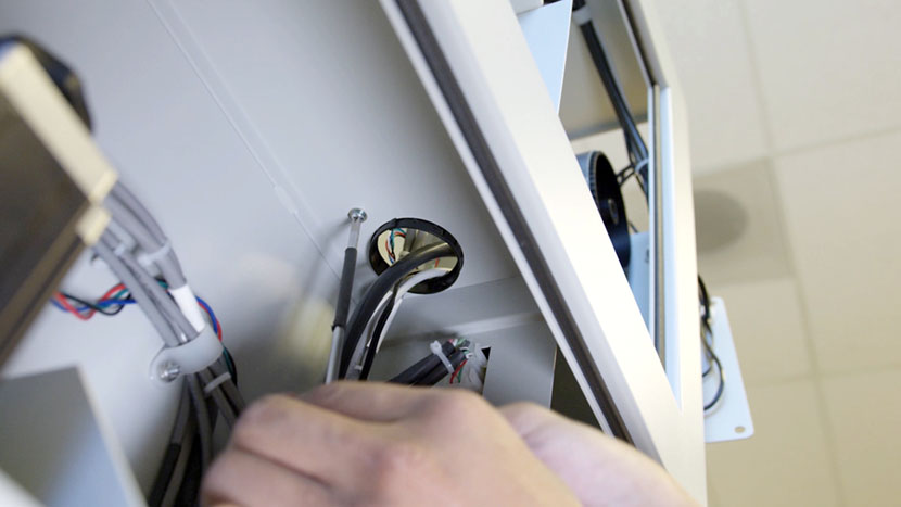
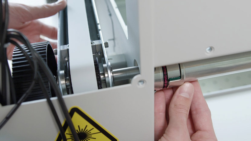
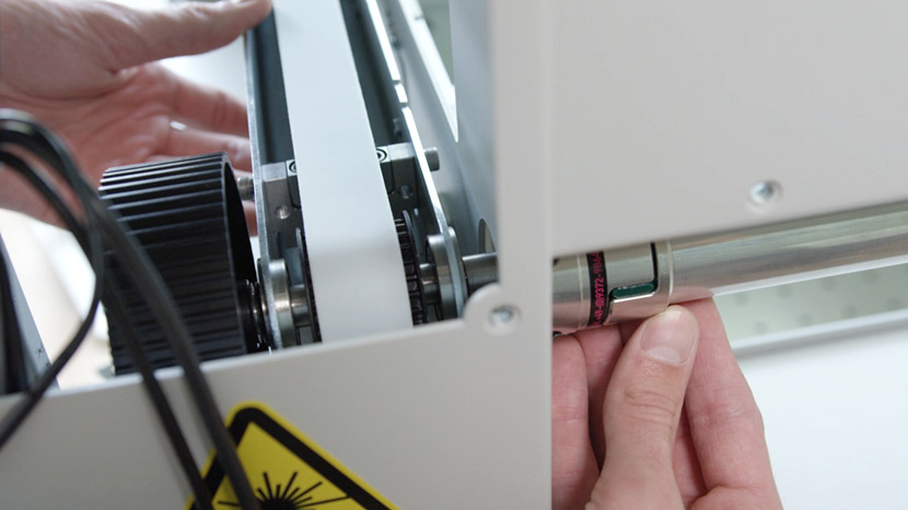
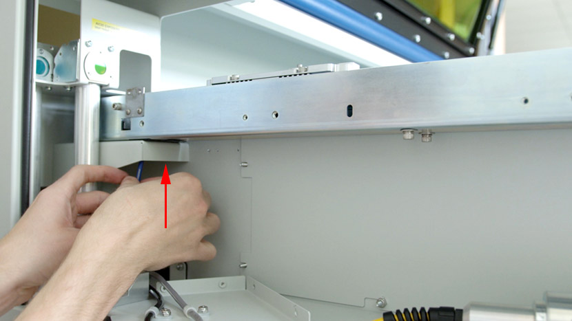
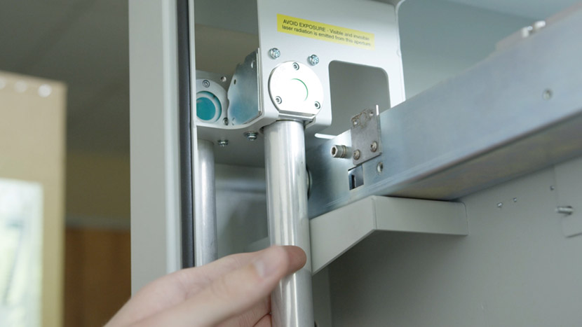
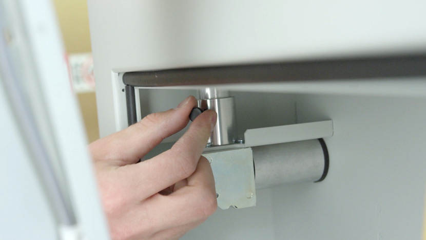
Manually loosen the black plastic screw near the bottom of the periscope.
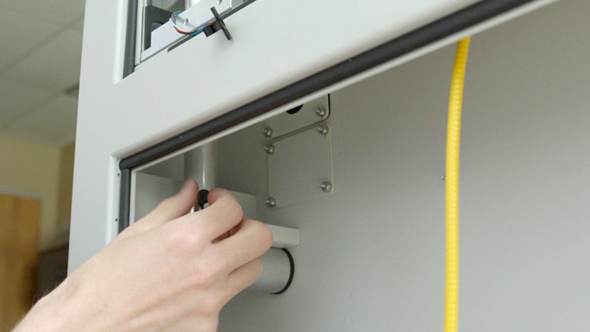
From the top compartment pull the metal tube out and set it aside.
Now remove the y-axis, rotating it 90 degrees outward while dropping it down and around the mounting brackets.
Push it slightly out the back through the open panel, then pull the entire axis out through the side of the compartment.

Install New Left Y-Axis
To install the new y-axis put the rear end of the axis into the machine with the axle pointing outward, push it slightly through the back open panel, then pull it forward into the machine, rotate it 180 degrees inward as you bring it up and over to rest on top of the brackets.
Slide the y-axis axle into the clamp in the rear of the machine.
Secure the front of the y-axis to its mounting bracket by using a 5/32” hex key to insert the two hex screws halfway so that the y-axis can still be lifted slightly.
Lift the y-axis and insert the black plastic shim, then tighten the 2 hex screws.
Secure the back of the y-axis to its mounting bracket the same way, using a 5/32” hex key to insert the 2 hex screws halfway.
Insert the black plastic shim, then tighten the 2 hex screws.
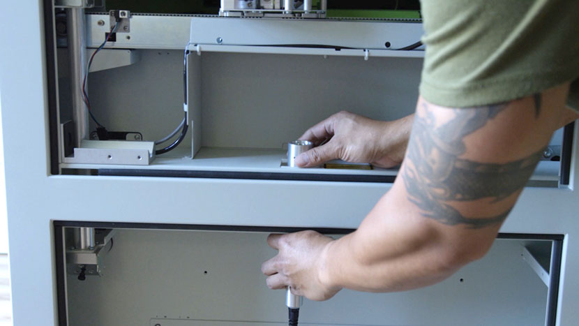
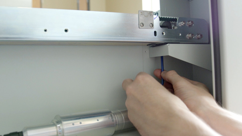
From the top compartment slide the metal periscope tube back into the housing in the bottom compartment.
Lift the tube up into the housing at the top, then manually tighten the black mounting screw at the bottom.
Use a Philips head screwdriver to insert the 2 screws that secure the rear axis sensor and switch guard to the side of the y-axis. Be sure to affix the switch guard on the sensor’s right side.
Now lift the compartment panel and slide it back into place over the 2 mounting screws on the interior side of the compartment.
Insert the 2 Philips head screws from underneath.
Use a Philips head screwdriver to insert the 3 screws that connect the compartment panels to the side of the y-axis.
Use a 5/16” nut driver to secure the 2 nuts over the 2 mounting screws.
Then use a Philips head screwdriver to insert the 2 screws that secure the front y-axis sensor and switch guard to the side of the y-axis. Be sure to affix the switch guard to the sensor’s left side.
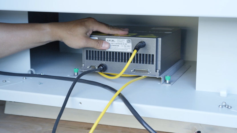
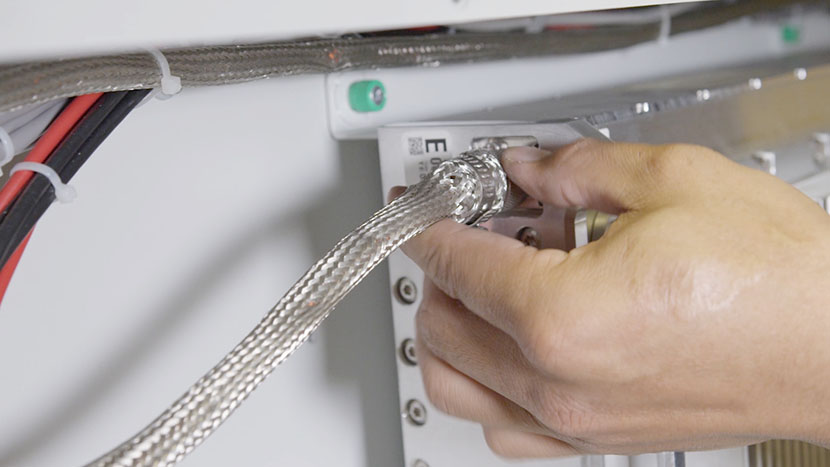
Now put the laser head back on the mount near the rear of the compartment.
Using a 5/32” hex key insert the 4 hex screws to secure the clamp around the laser head. Be sure to create a good seal by gently pressing the laser head against the back felt pad.
Align and Clamp
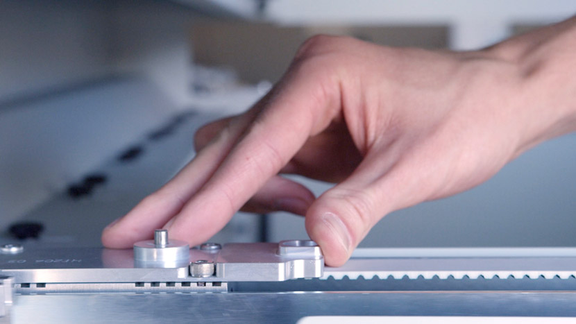
Move the Y-Axis Assembly on either side of the machine as far back to the rear as they can go. This will ensure the two sides are in alignment.
Use a 5/32″ hex key to secure the clamp screws on the rear axle. There are 2 clamp screws on either side of the machine. Be sure to secure any that you loosened earlier in the process.
Replace X-Axis Assembly
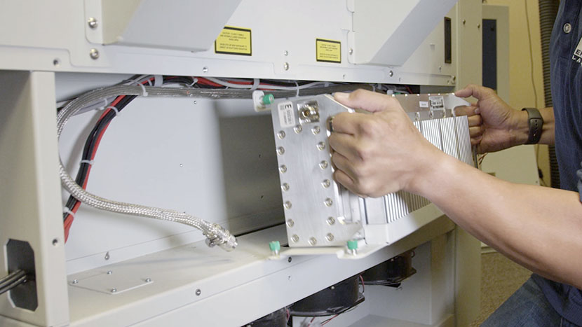
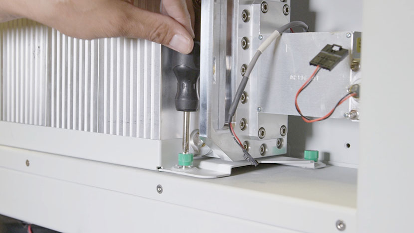
Place the x-axis assembly back onto its mountings and secure it by tightening its 4 green captive screws, lining it up with the guide pins so there is no space between the bottom of the assembly and the screw mounts.

Use a short or offset Philips head screwdriver to tighten the green captive screws on both sides.
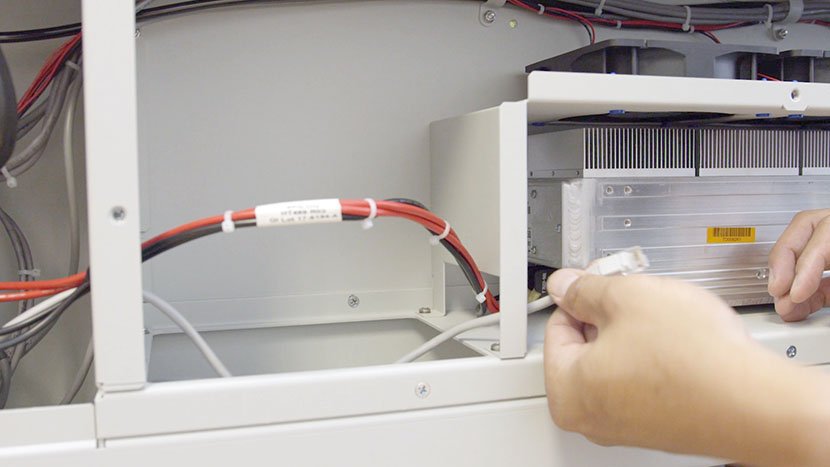
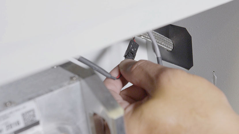
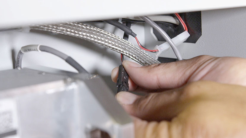
Next connect the wire harness by plugging in the black connector then the white connector.
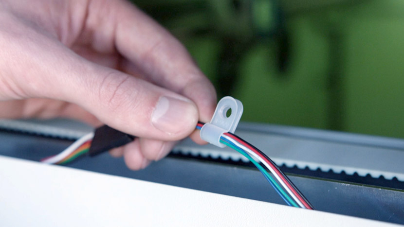
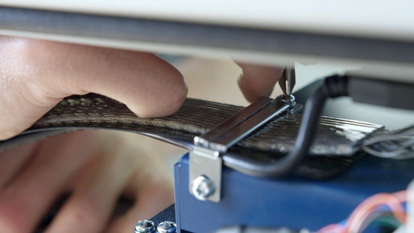
Retrieve the wire harness clamp and position the wire harness and its plastic guard so that the harness is on top of the guard and both are under the clamp on the x-axis assembly.
Be sure that the wires between the wire harness and the circuit board have some slack and are not drawn too tight. Secure the clamp by inserting the two screws.
Reinsert the air assist tube on the left end of the assembly. The ring will pop out once the tube is successfully inserted.
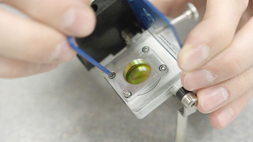
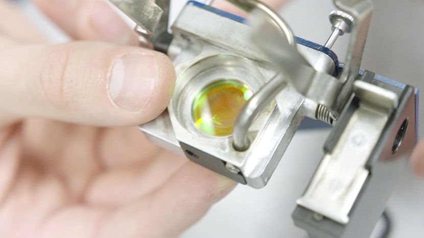
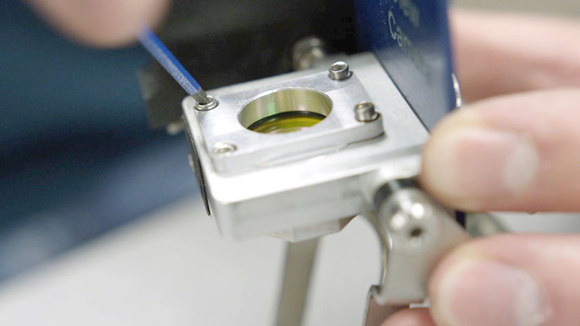
Reinstall the lens assembly by sliding it into the housing and tightening the 3 screws on its front face.
Reinstall Panels
Now use a 5/32” hex key to reattach all of the panels on the machine.

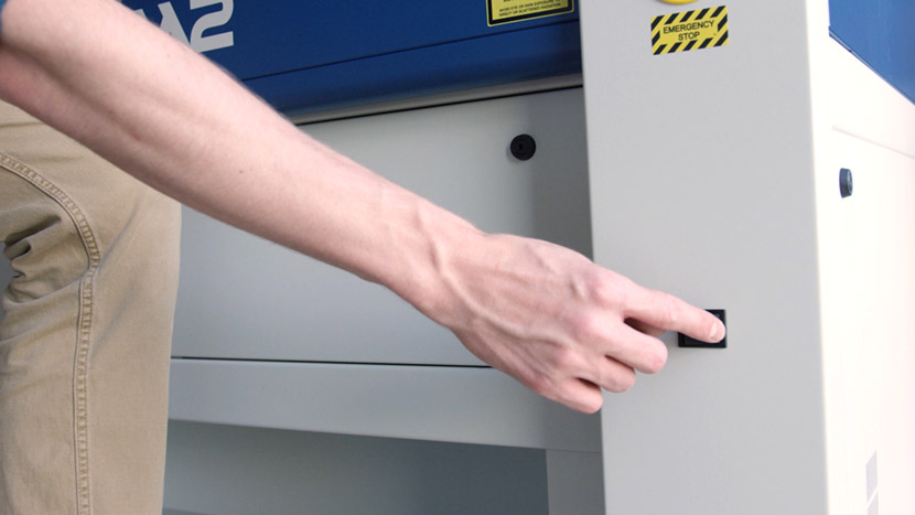
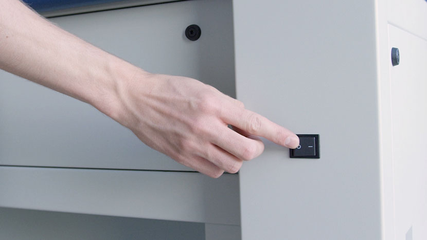
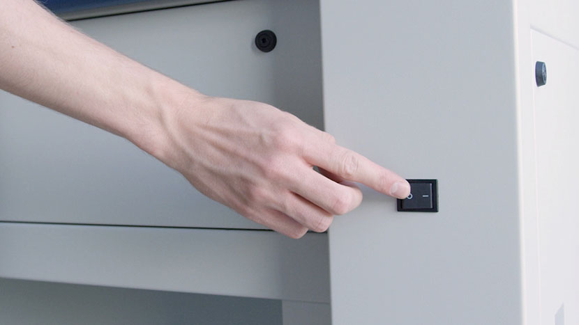
Then plug the machine in and turn it on.