Epilog Laser System Initial Setup
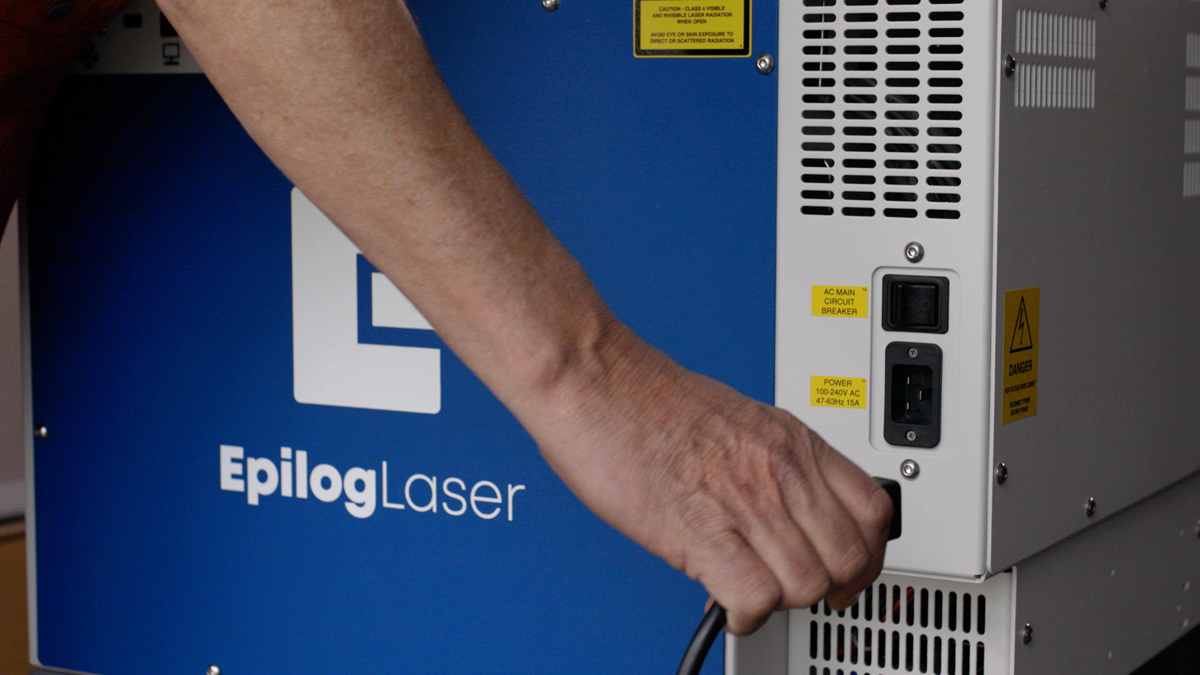
Step 1: Turn on Your Machine
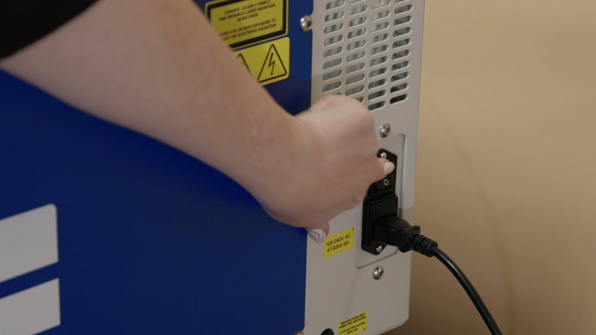
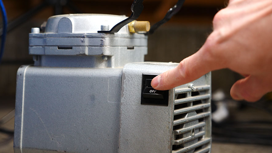
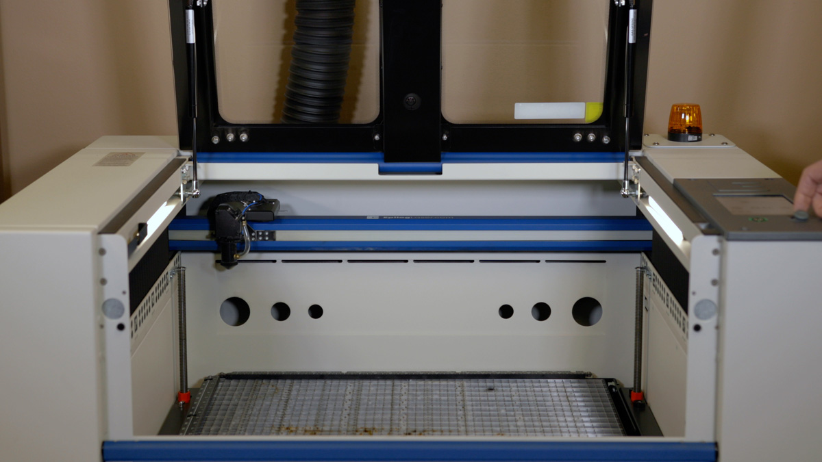
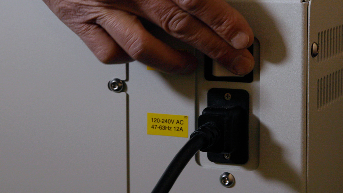
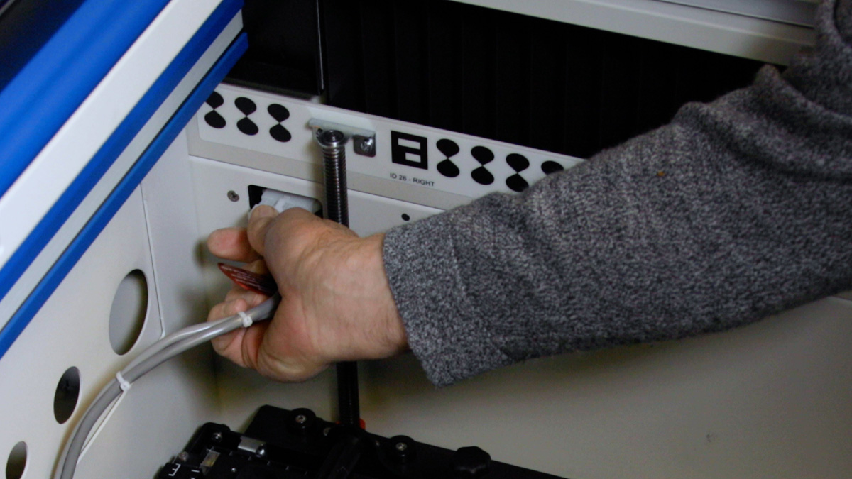
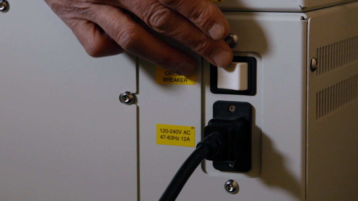
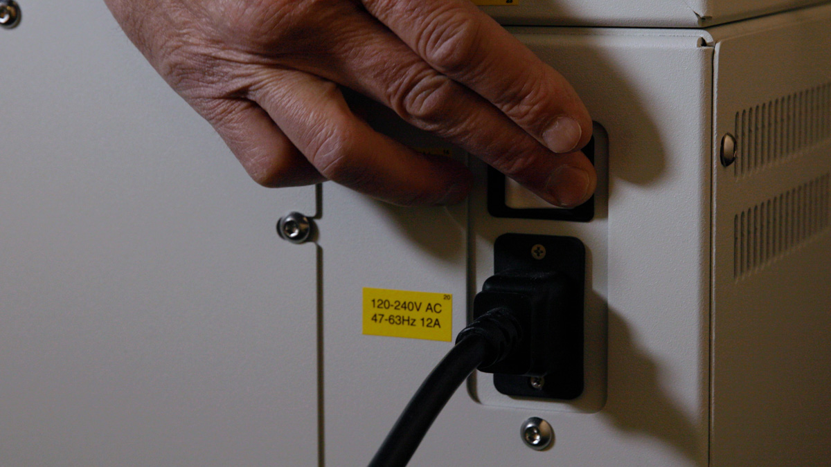
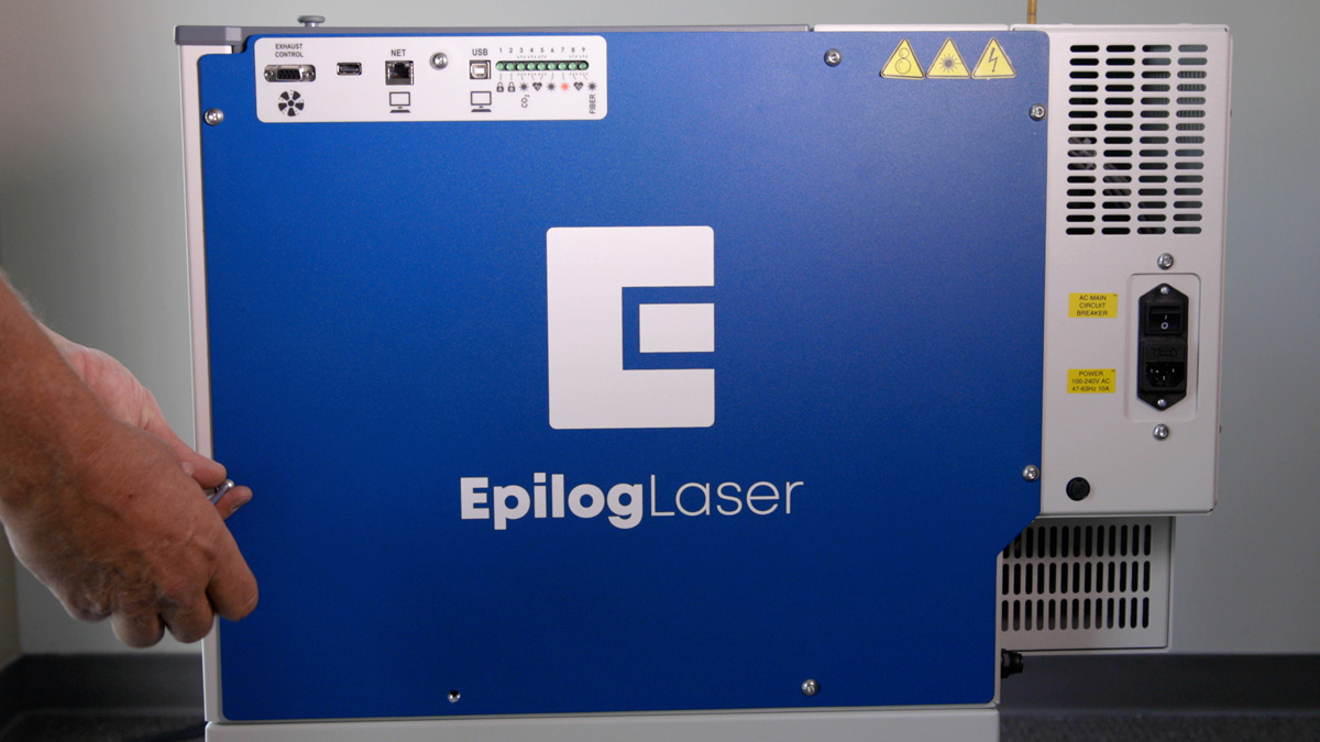
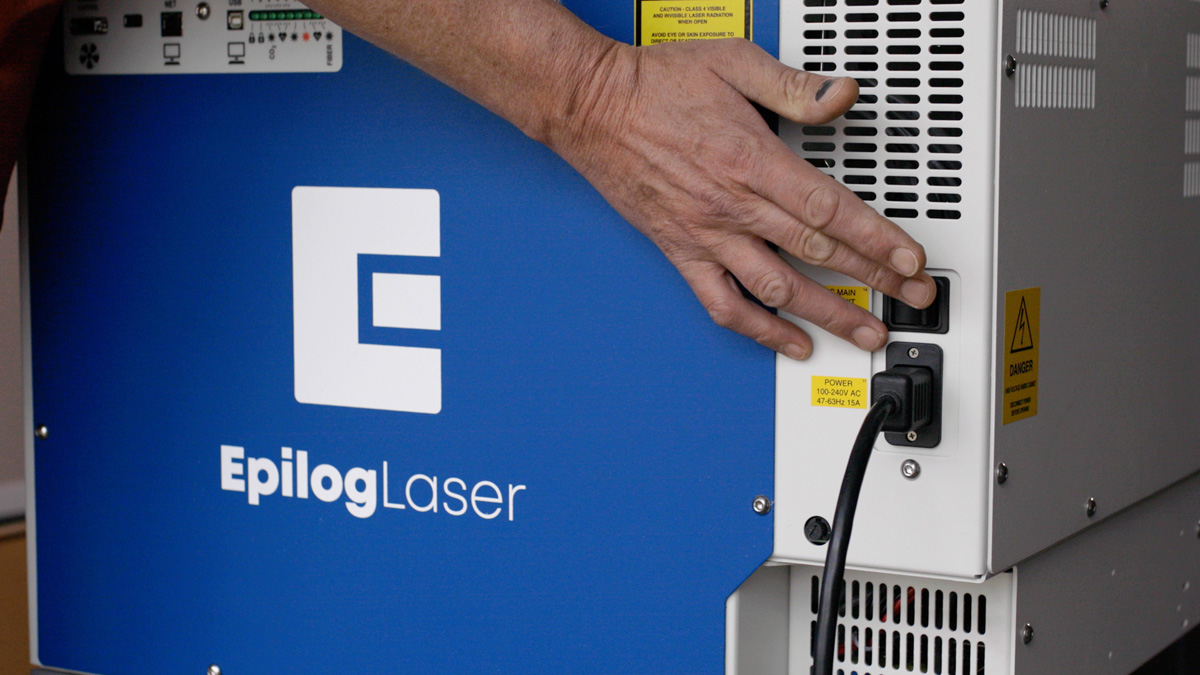
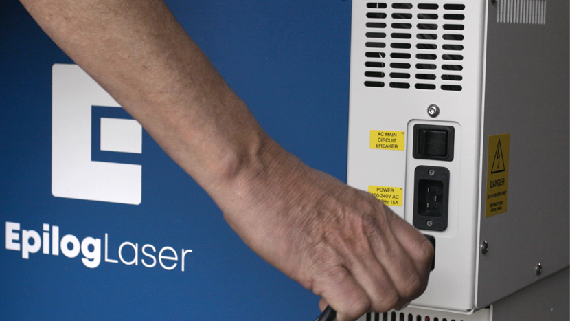
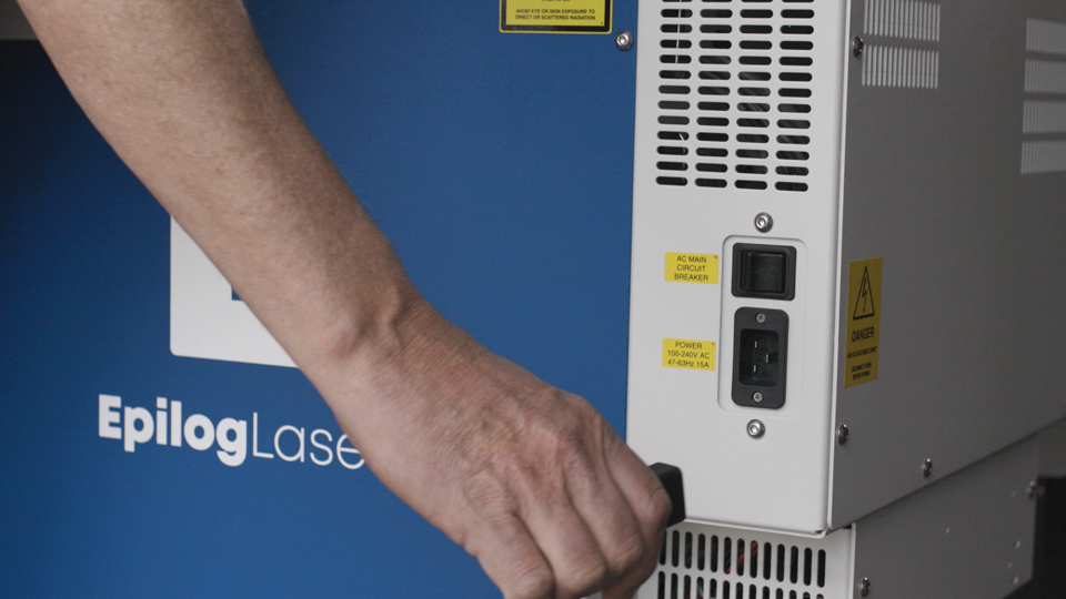
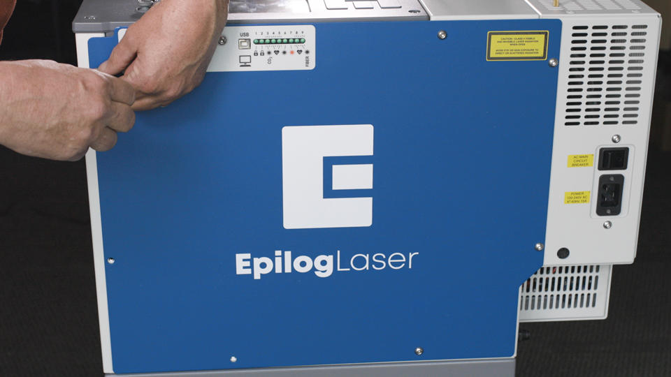
Begin by turning on your laser system. The power switch is located on the side near the back of the machine for all models: Fusion Maker, Edge, Pro, and Galvo.
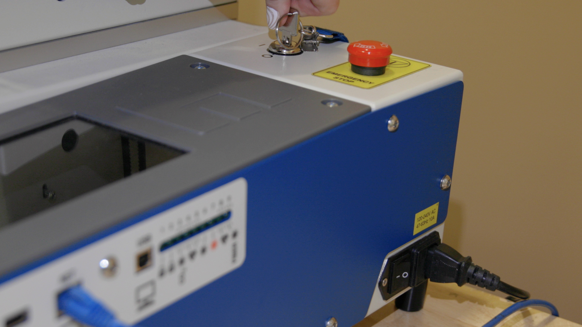
For the Fusion Pro 48 and Fusion Galvo G100, there’s an additional key to turn on the machine. This key also helps restrict access to the system. Ensure it’s in the ‘on’ position.
Step 2: Demo Walkthrough
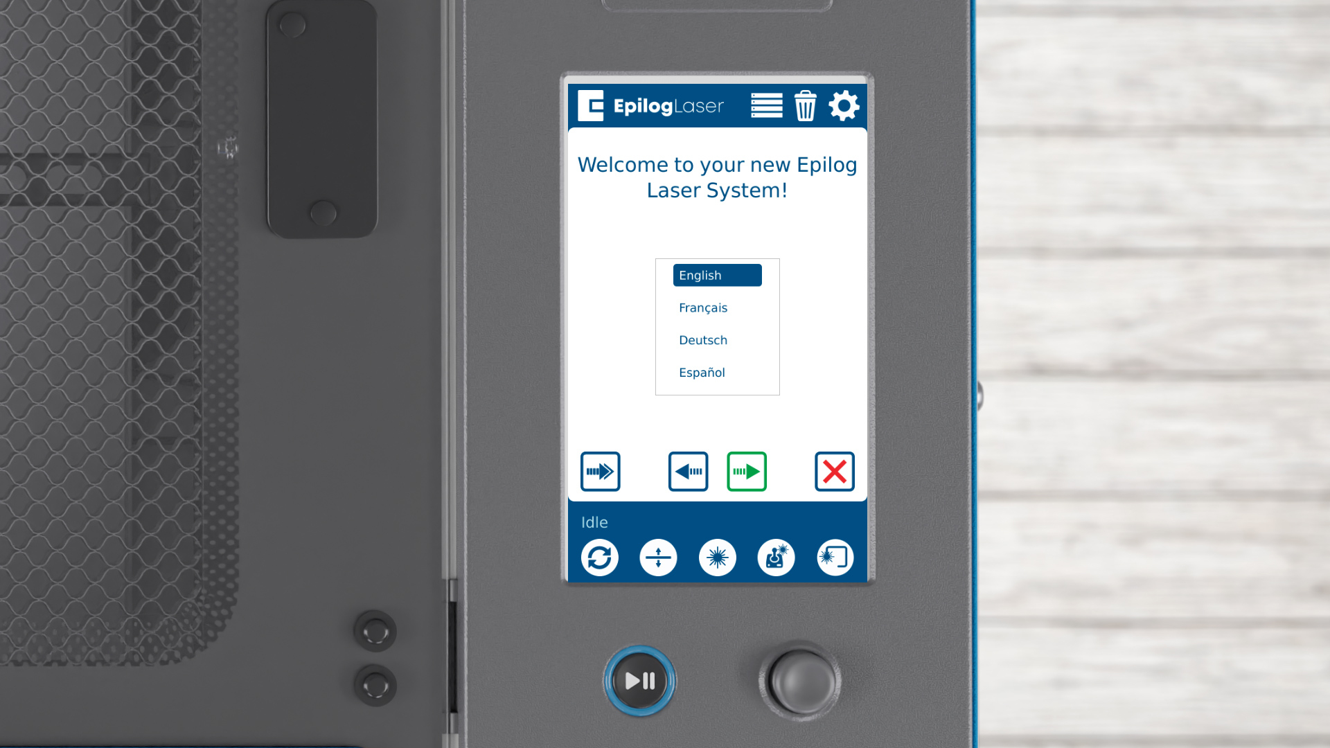
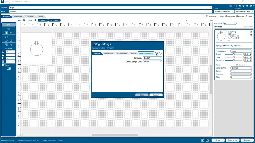
Once the machine boots up, the setup wizard will launch. First, choose your language. Click the arrow to proceed to the next step.
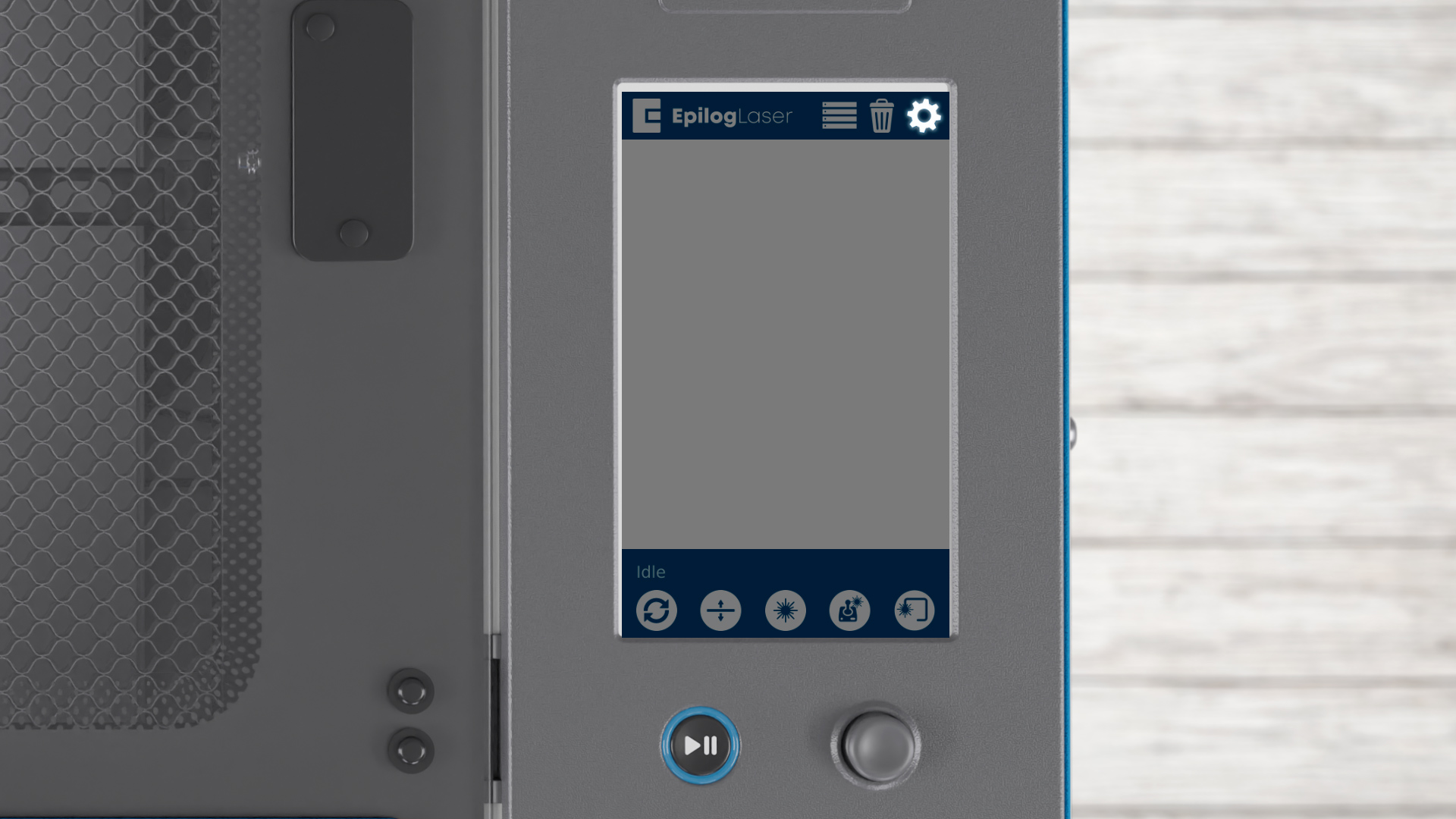
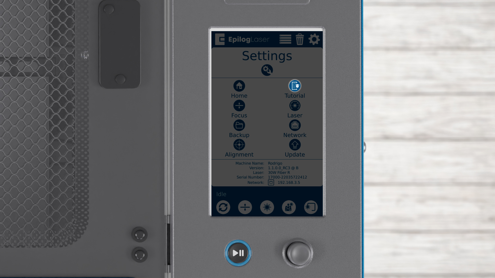
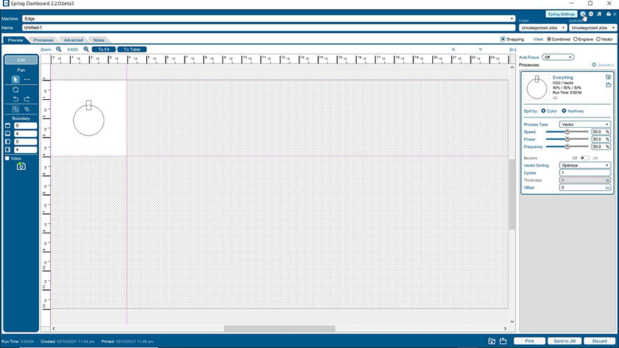
If the startup screen does not appear, such as if you purchased your system used, you can access this feature by clicking the Settings icon. Now click the Tutorial icon.

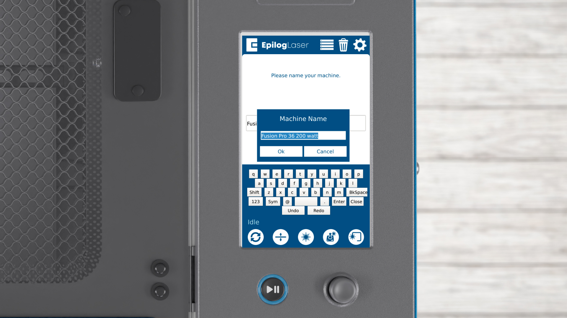
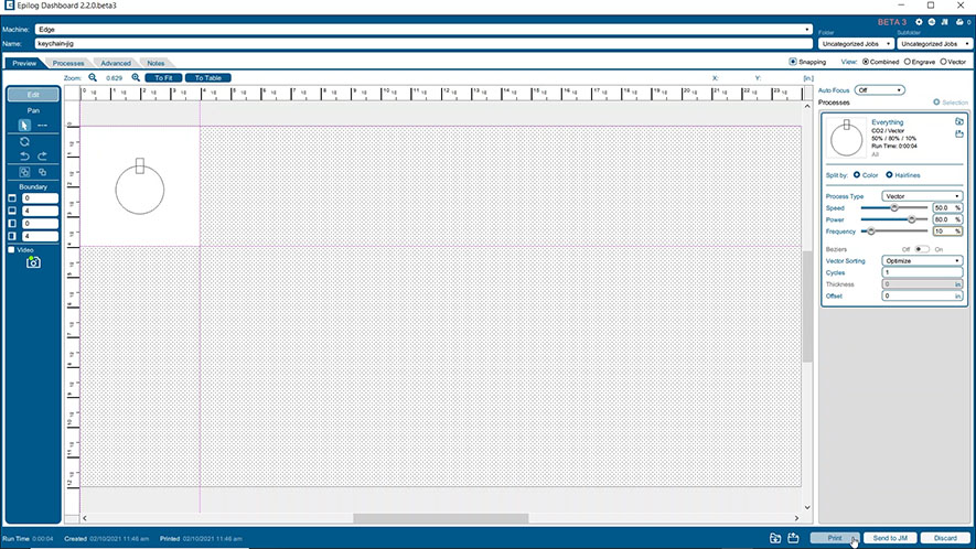
Next, you’ll be asked to name your system. Click in the box to add a name. Get creative or keep it simple – name it however you like, then click OK.

Click the arrow to proceed to the next step.

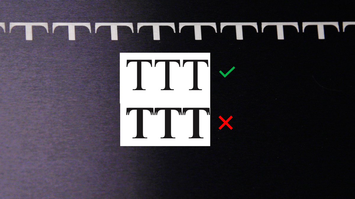
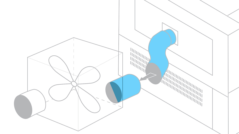
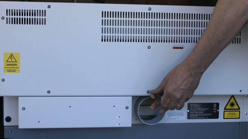
A reminder will appear about connecting an exhaust or filtration system. This is essential for proper airflow and safety. Click the arrow once you have your exhaust unit connected.
Step 3: Run Demo Job on Fusion Maker/Edge/Pro
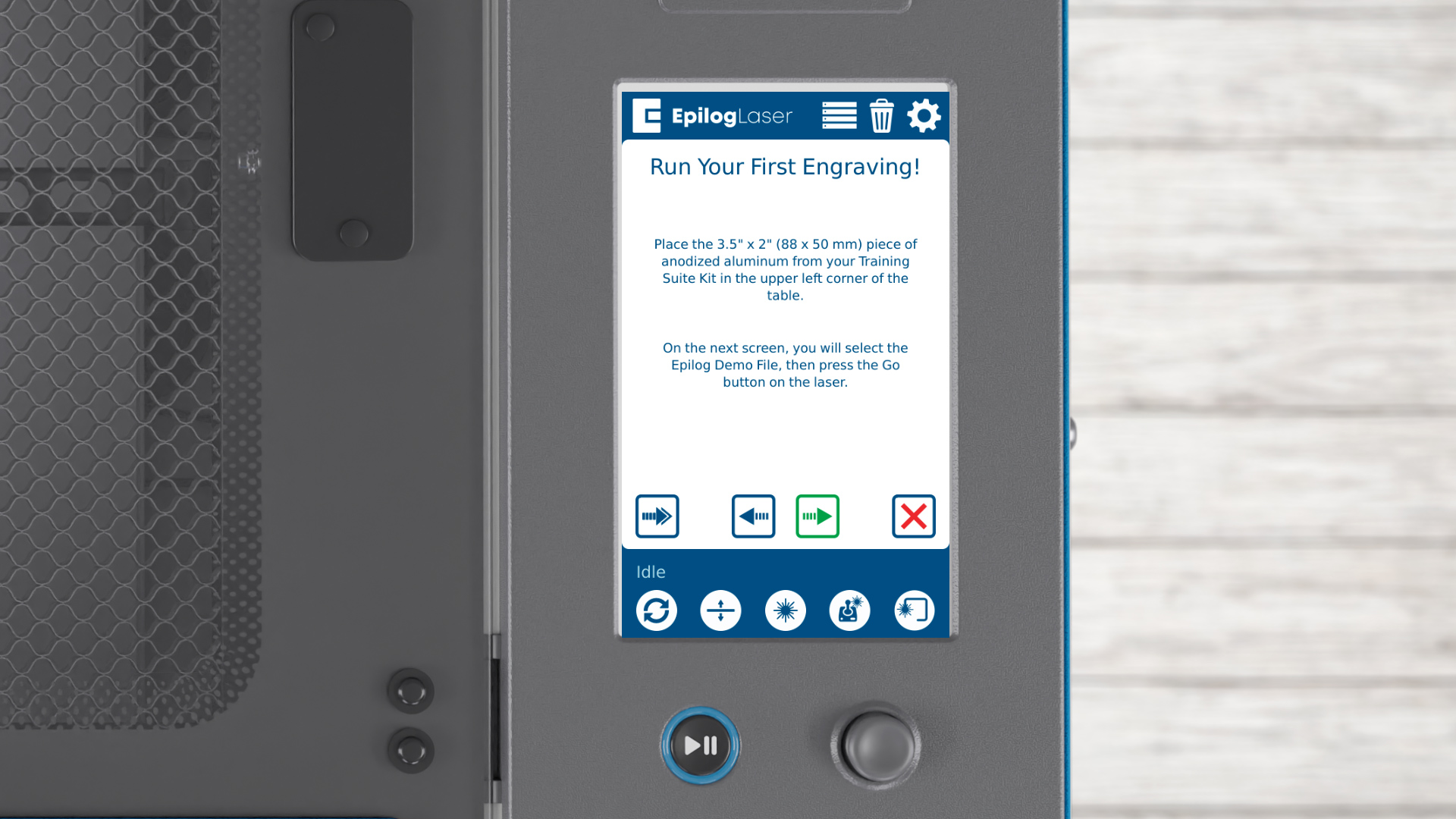

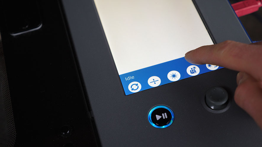
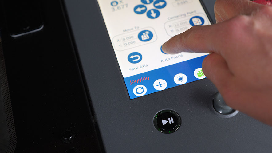
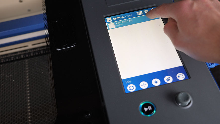
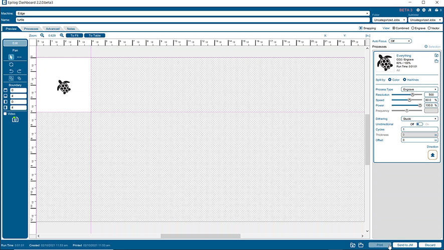
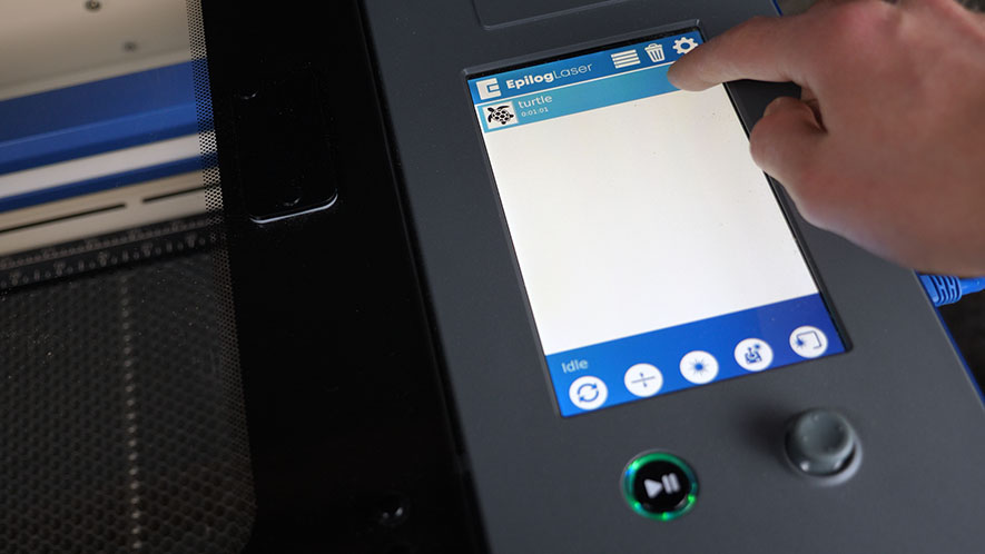
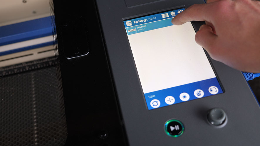
Now, let’s see the laser in action! Press the arrow to load the job in your laser system. You’ll see a file named ‘Epilog Demo’ in the file list.
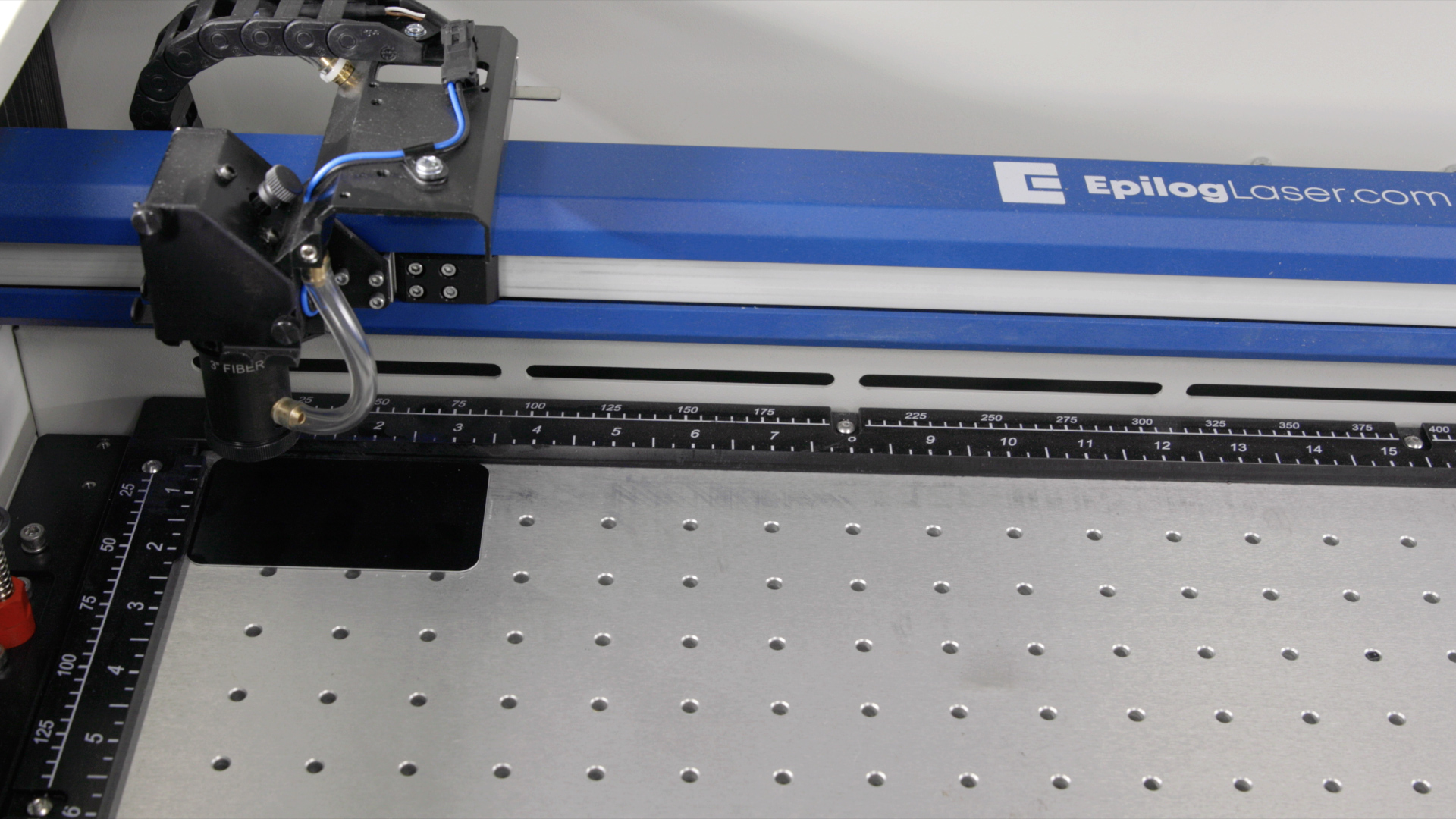
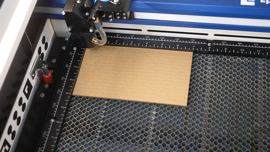
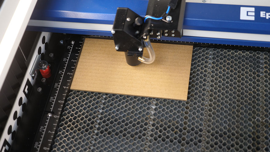
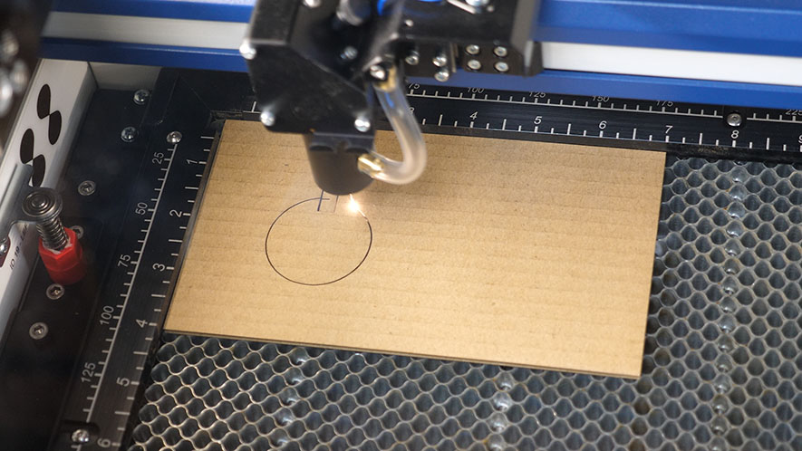
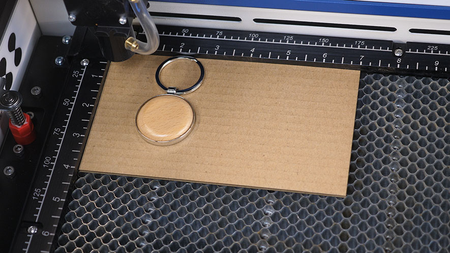
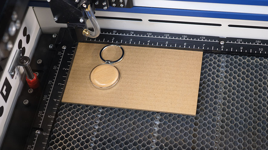
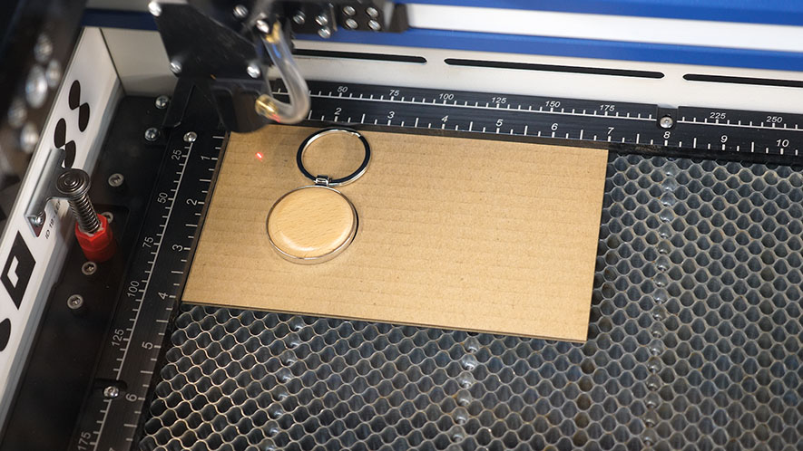
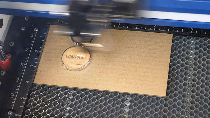
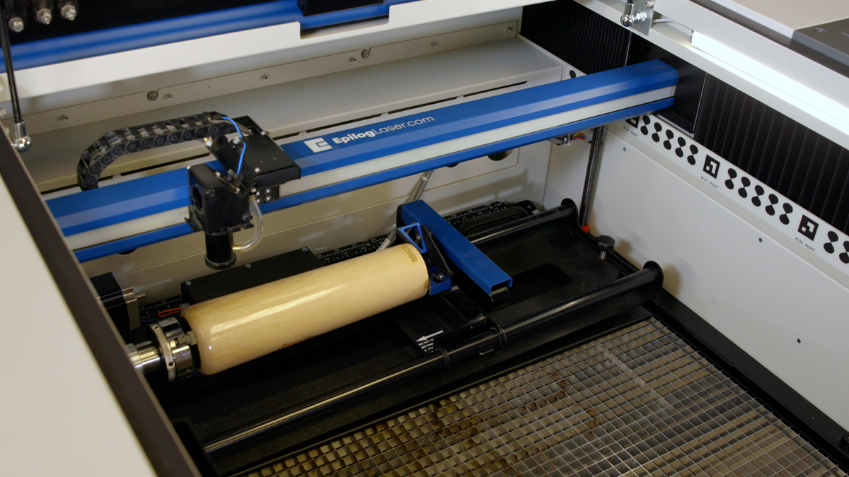
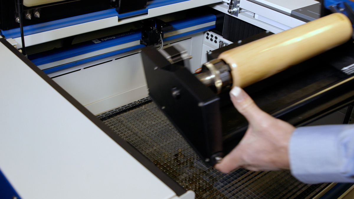
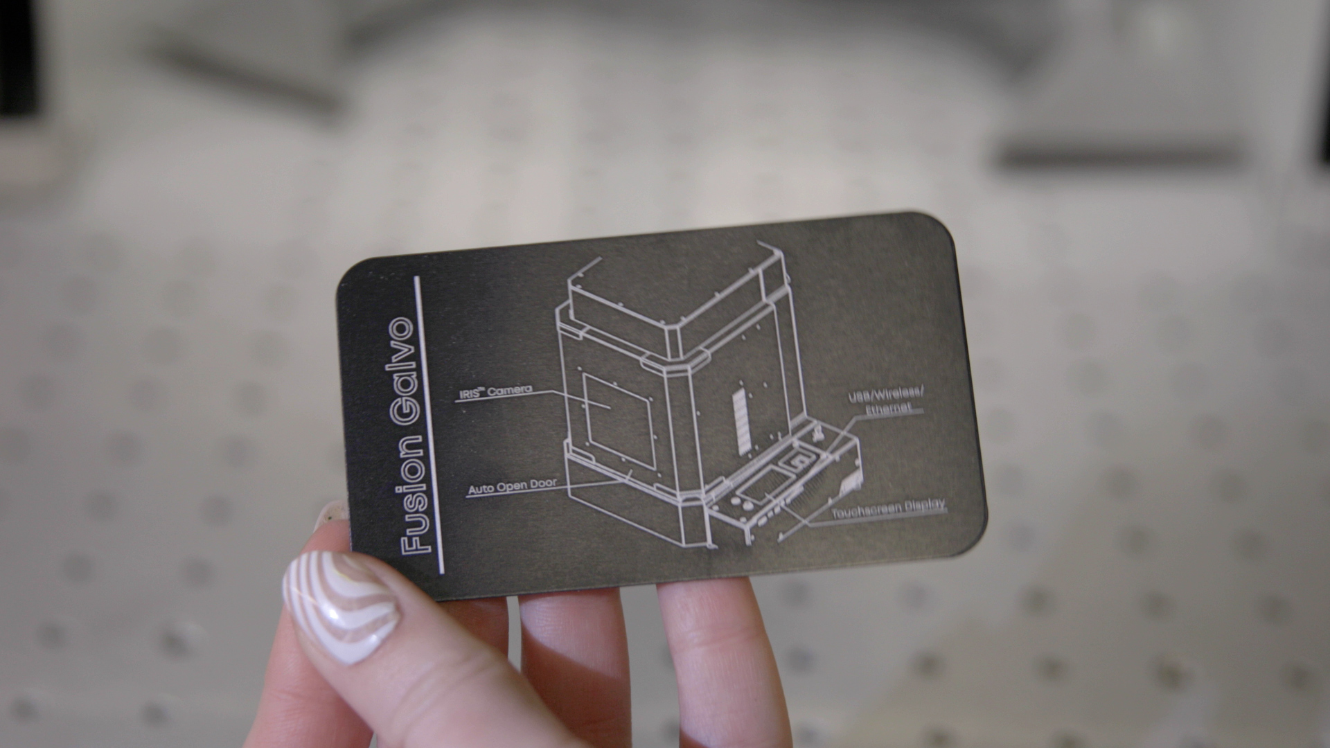
In your Training Suite Kit, you’ll find a 3.5” x 2” anodized aluminum piece. For Fusion Maker, Edge, and Pro models, place it in the top-left corner of the engraving table.
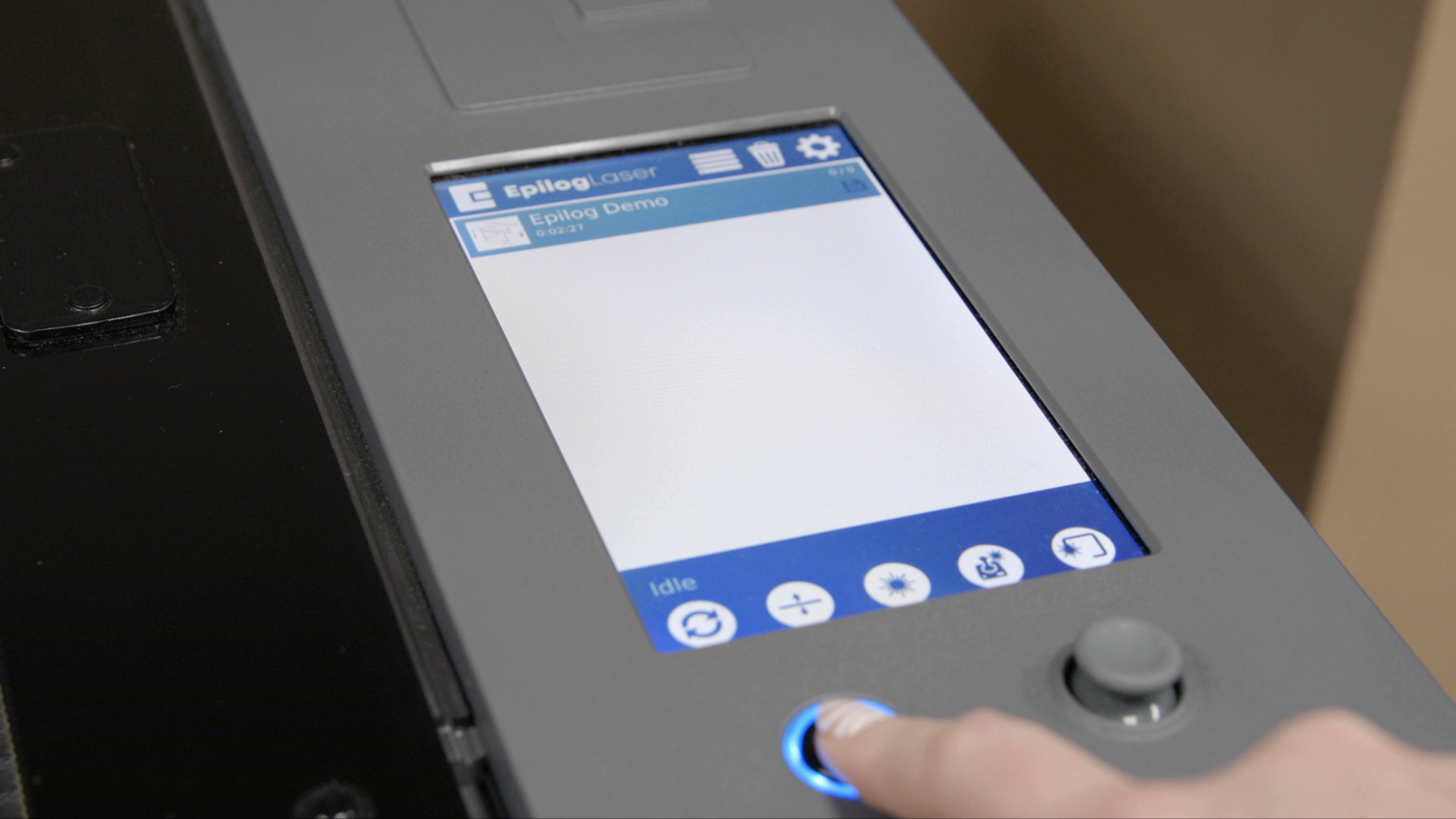
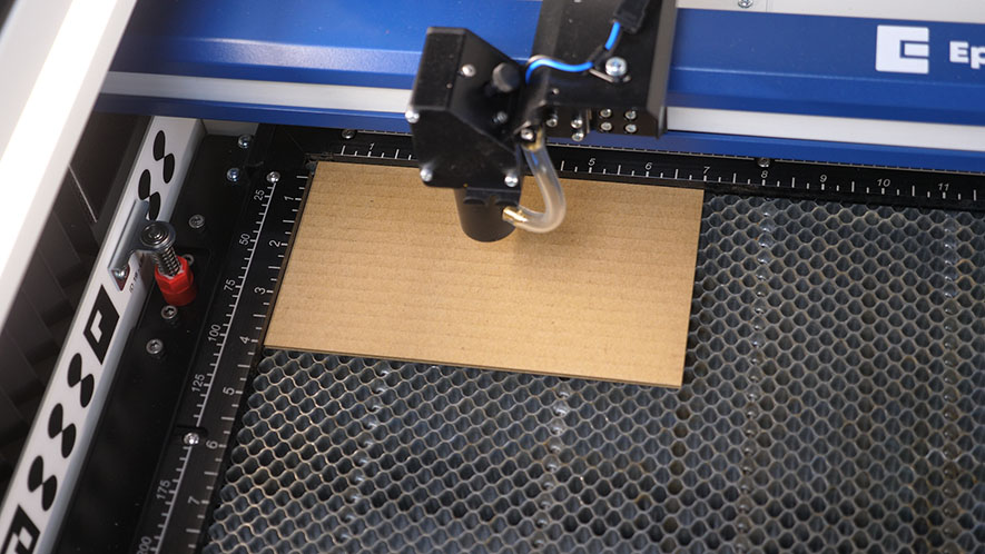
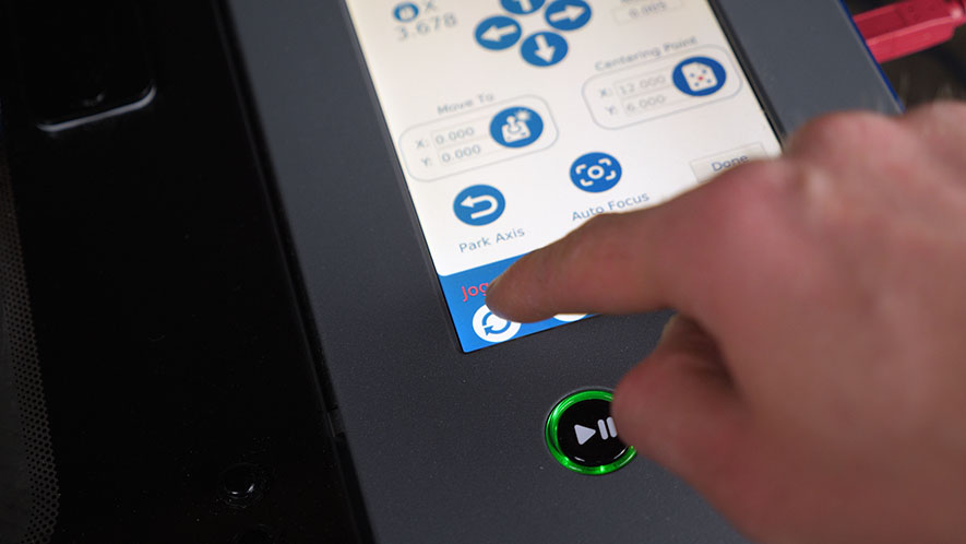
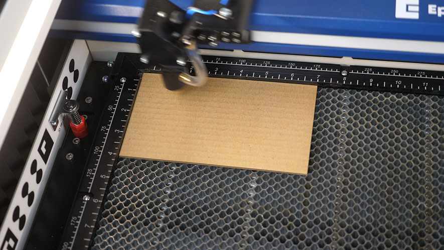
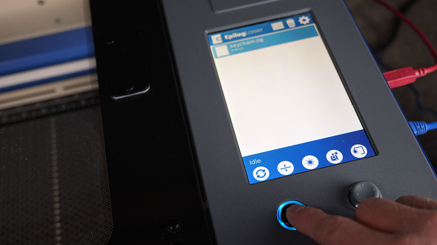
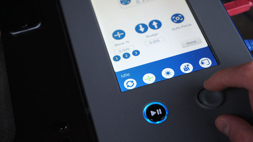
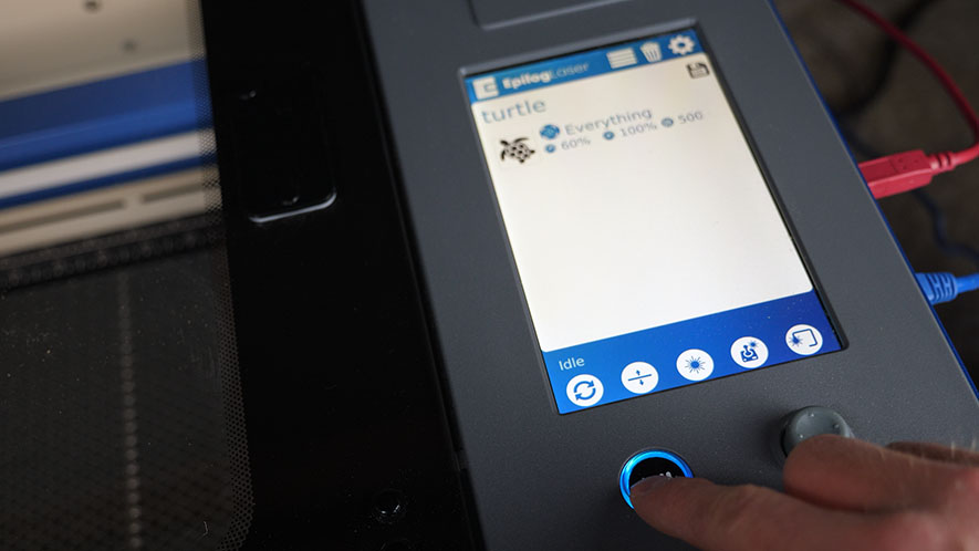
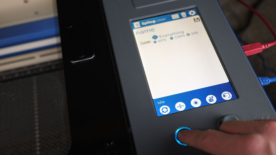
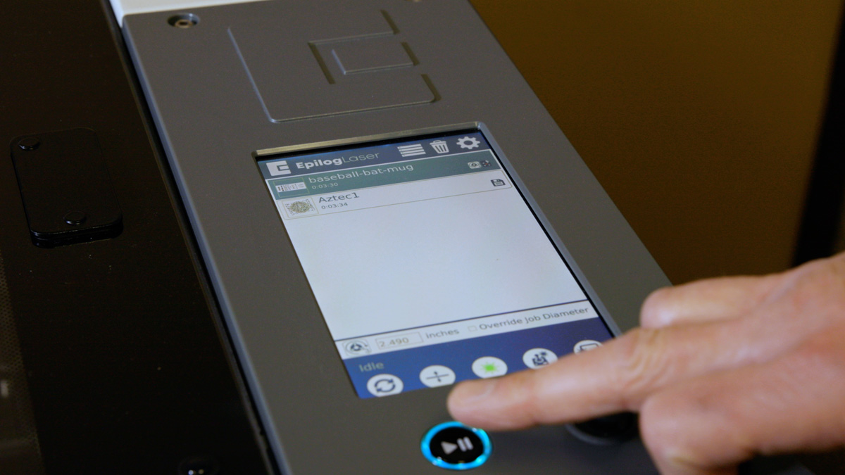
Press the start button to run the job.
Step 4: Run Demo Job on the Fusion Galvo
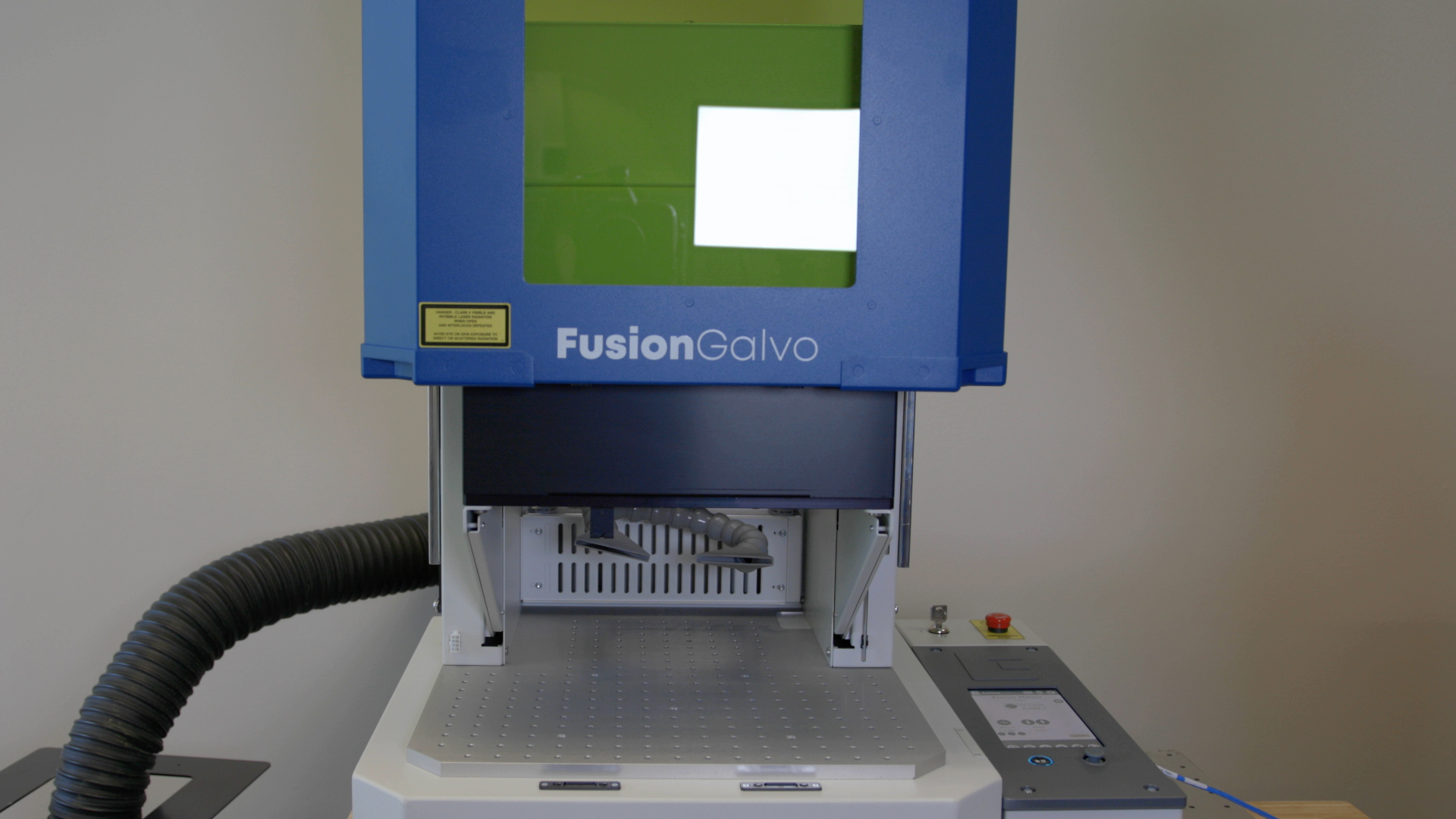
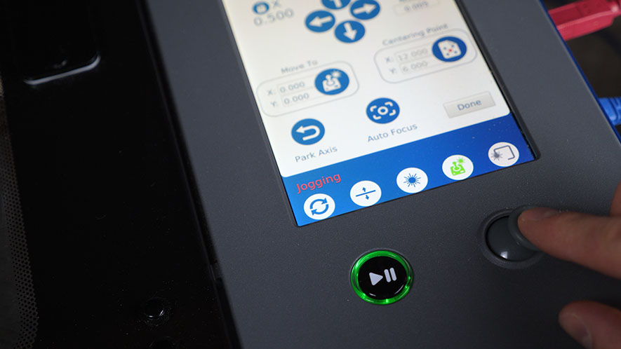
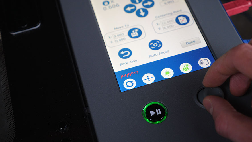
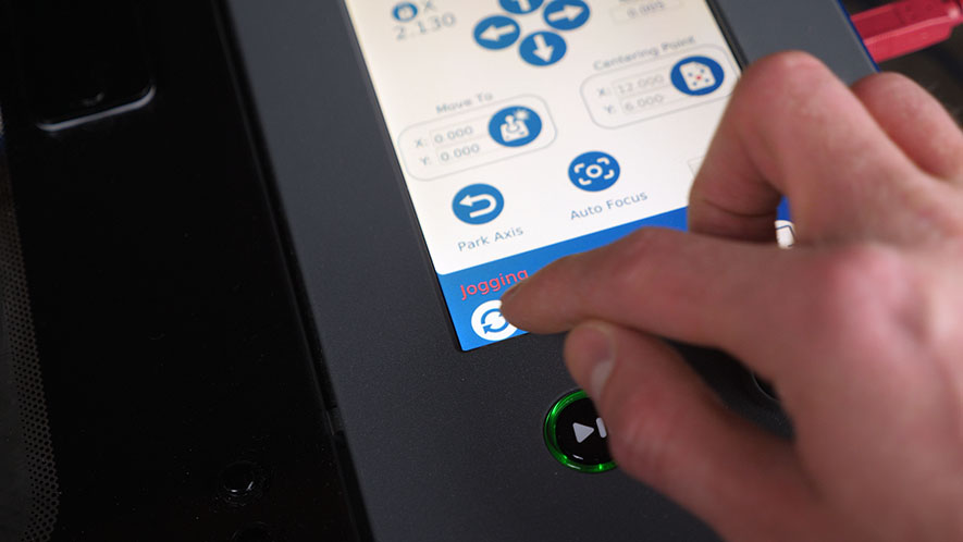
For the Fusion Galvo, raise the door by clicking the raise door icon.
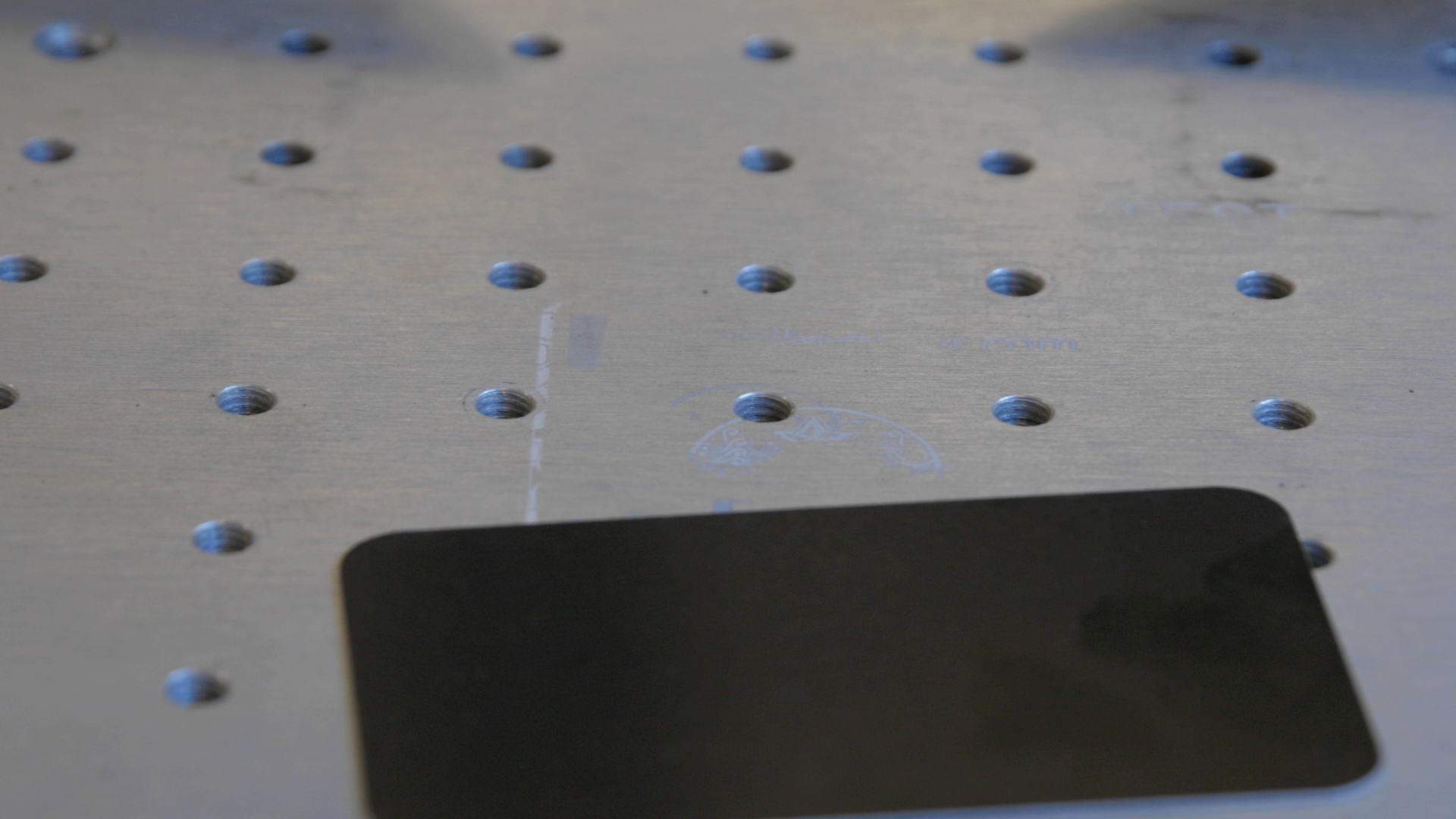
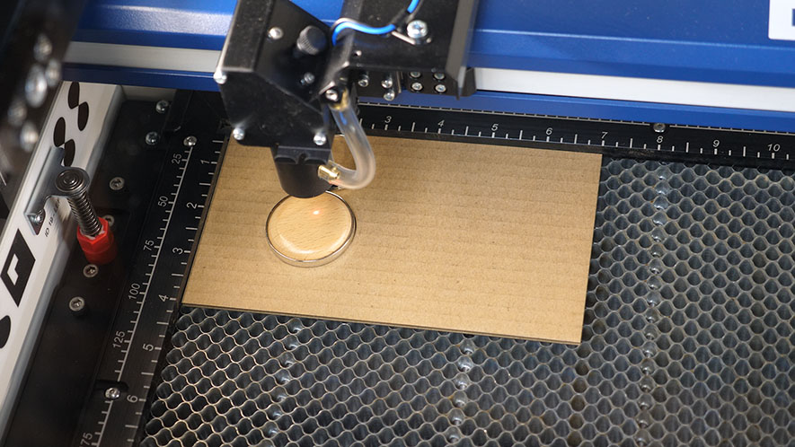
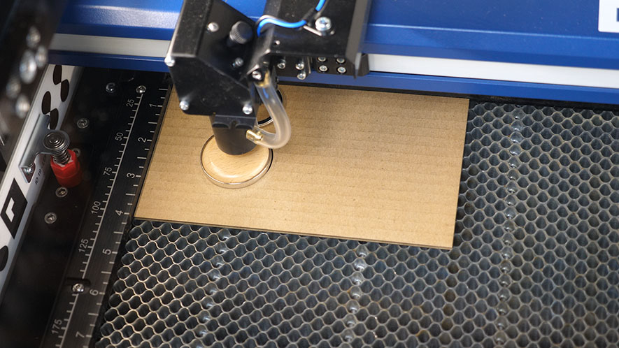
Place the anodized card at the center of the engraving table.

Press the arrow to continue.
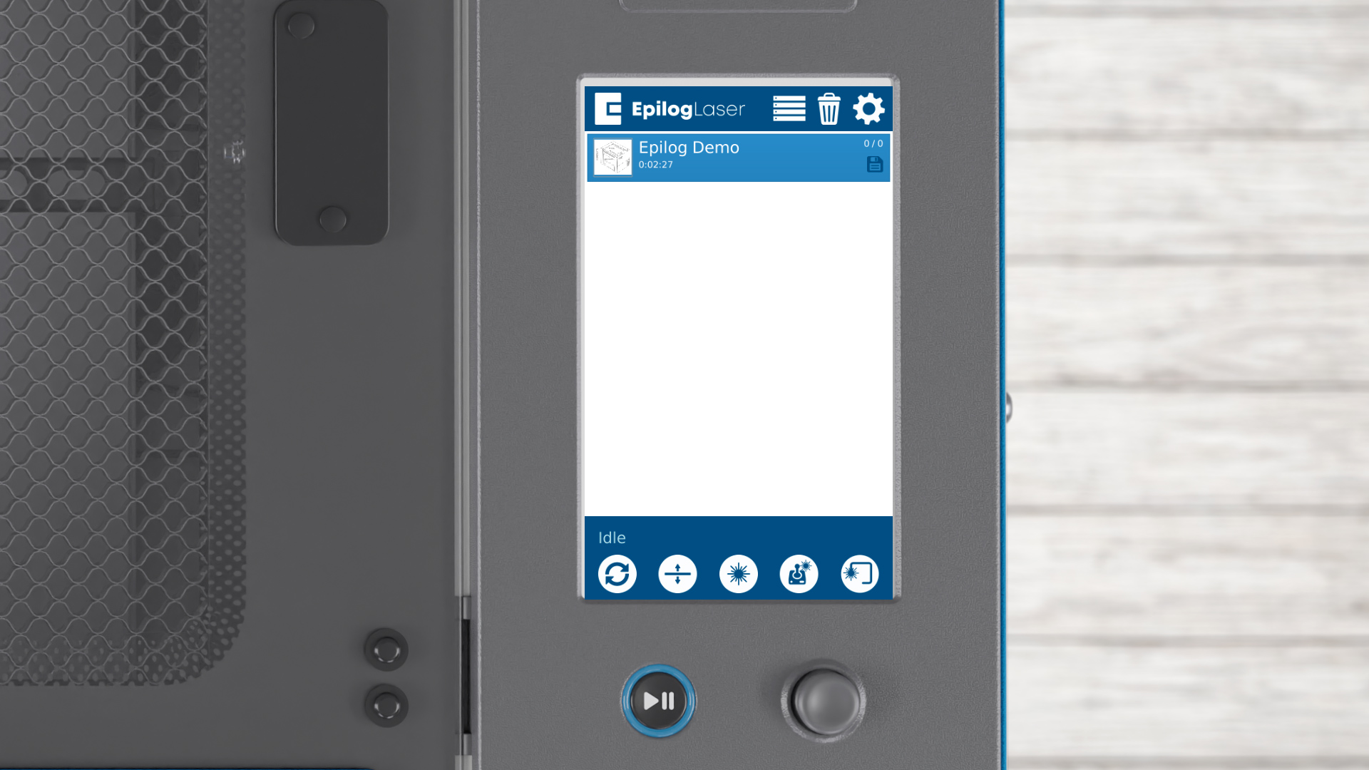
You’ll see a file named ‘Epilog Demo’ in the file list.
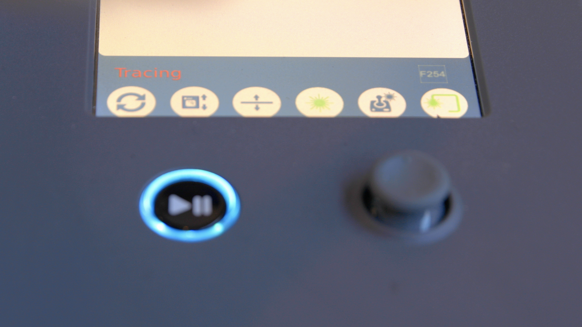
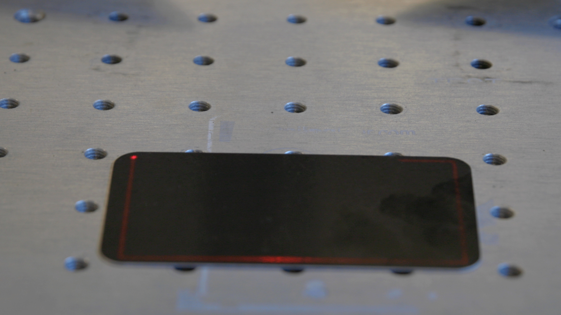
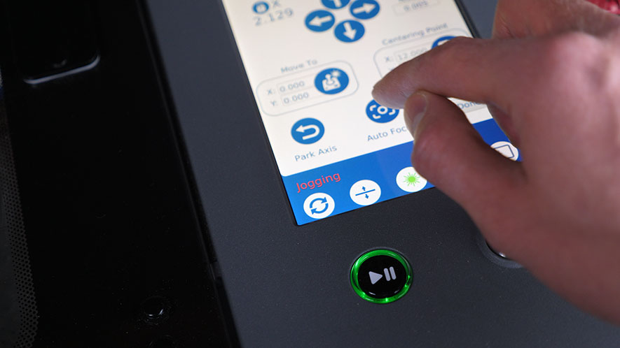
Select the trace icon to place your artwork.

Press the start button to start engraving.
With the first engraving successfully completed, next, the setup wizard will guide you through connecting the laser to your computer or network.
Step 5: Connecting to the Laser

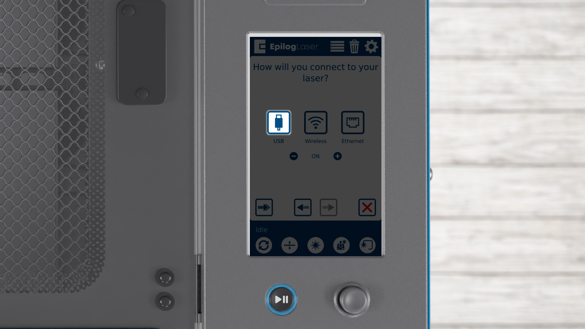
You can choose USB, Wireless, or Ethernet. Let’s start with USB options – press the USB button.
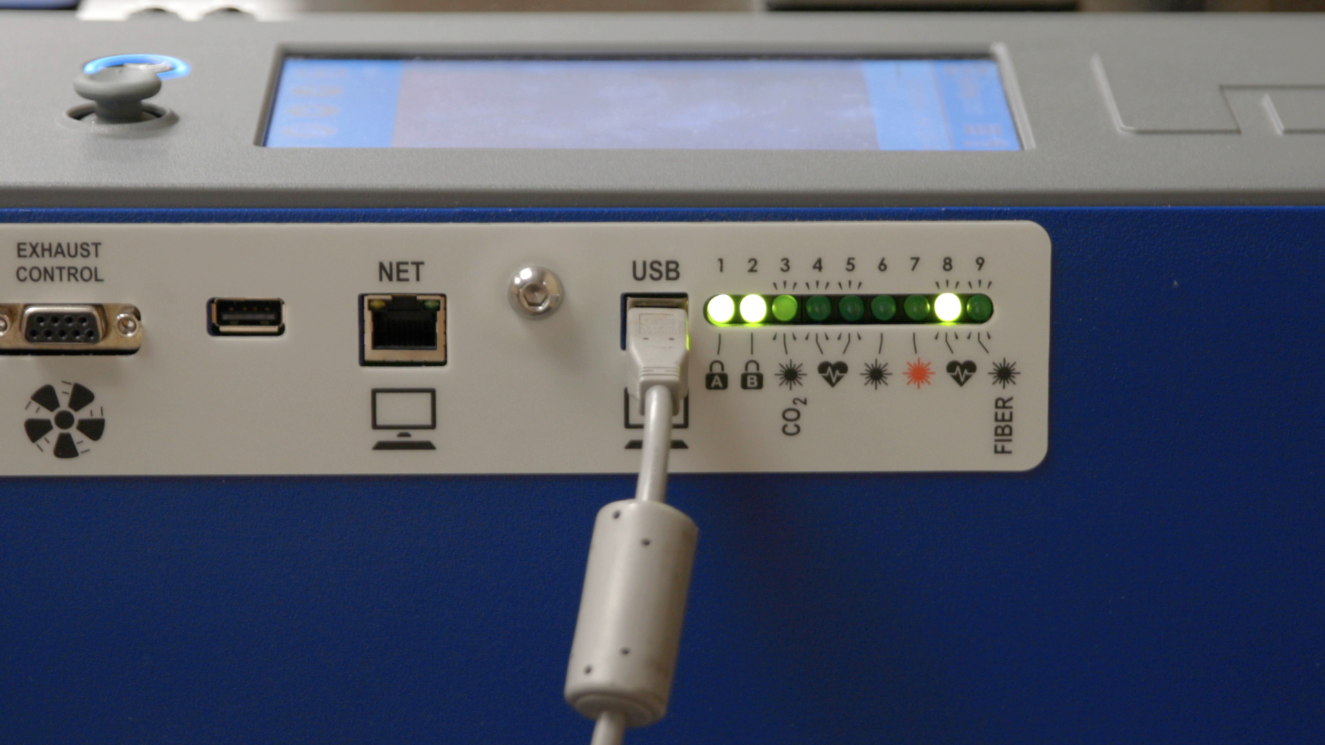
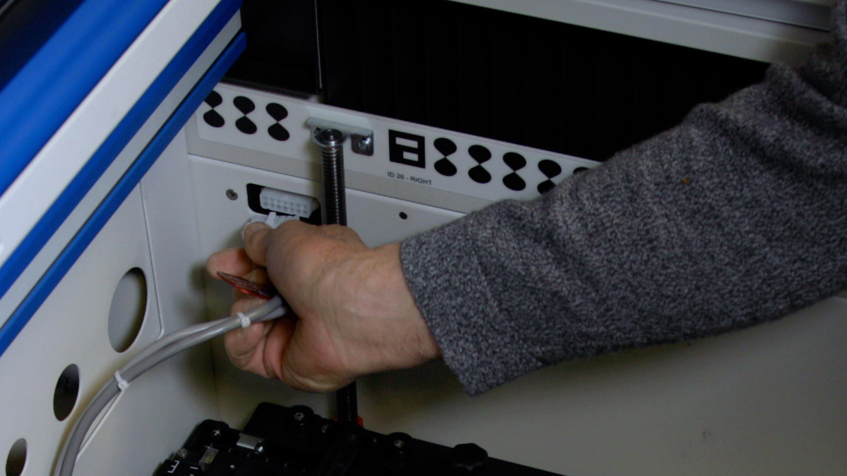
Connect a USB cable from your laser to the computer.
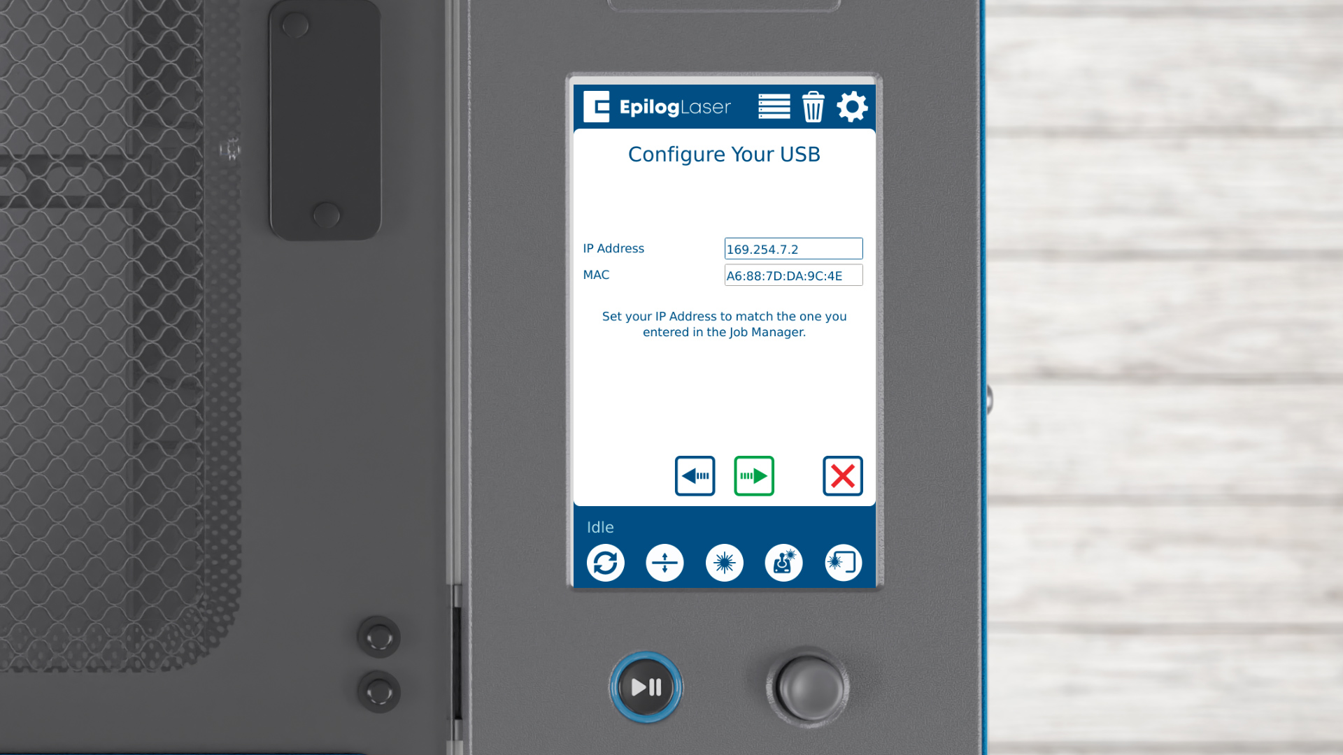
Click the arrow to continue.
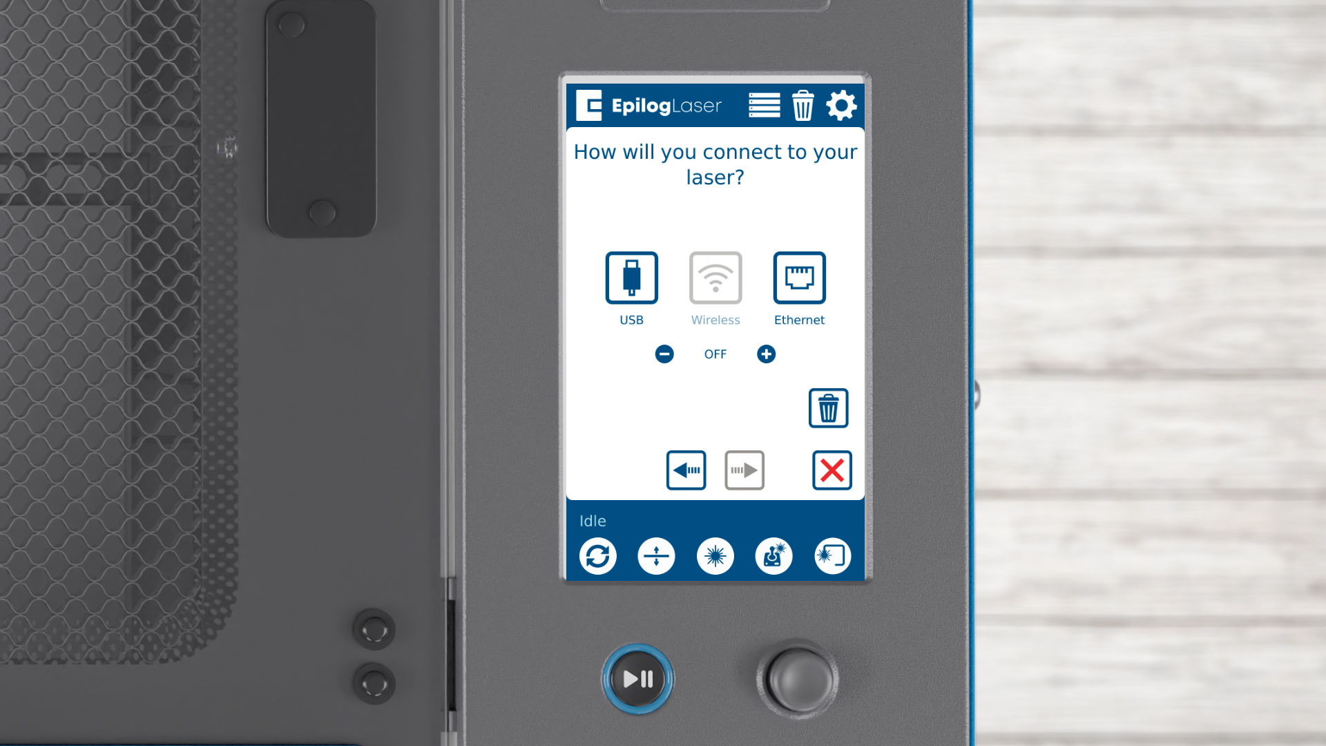
Next we’ll look at the wireless capabilities of the laser. Below the Wireless button, there’s a toggle for turning wireless capabilities on or off. If needed, you can completely disable wireless by pressing the minus button.
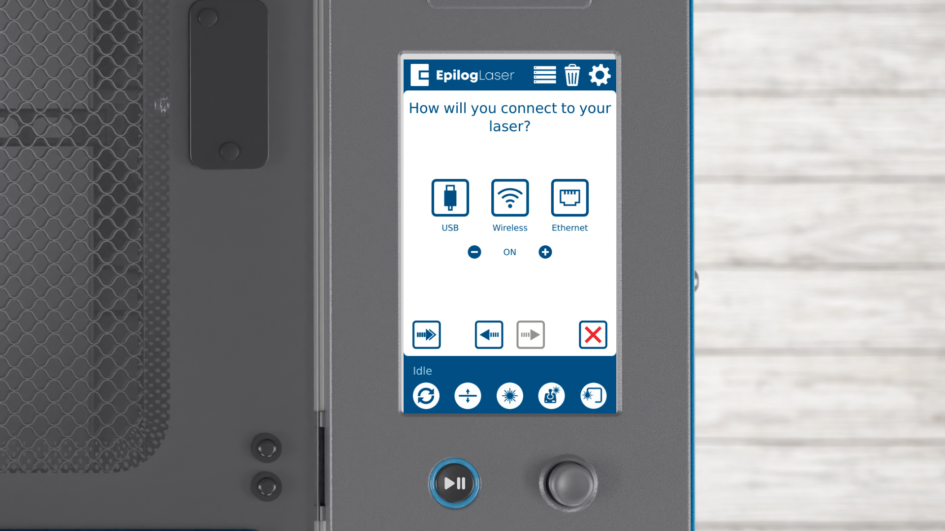
This disables the laser’s wireless capabilities, but let’s turn them back on by clicking the plus button.
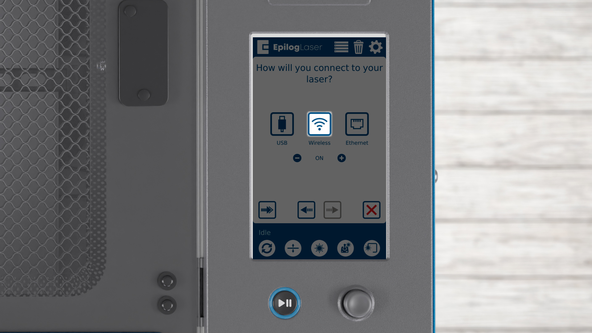
To connect via wireless, press the wireless button.
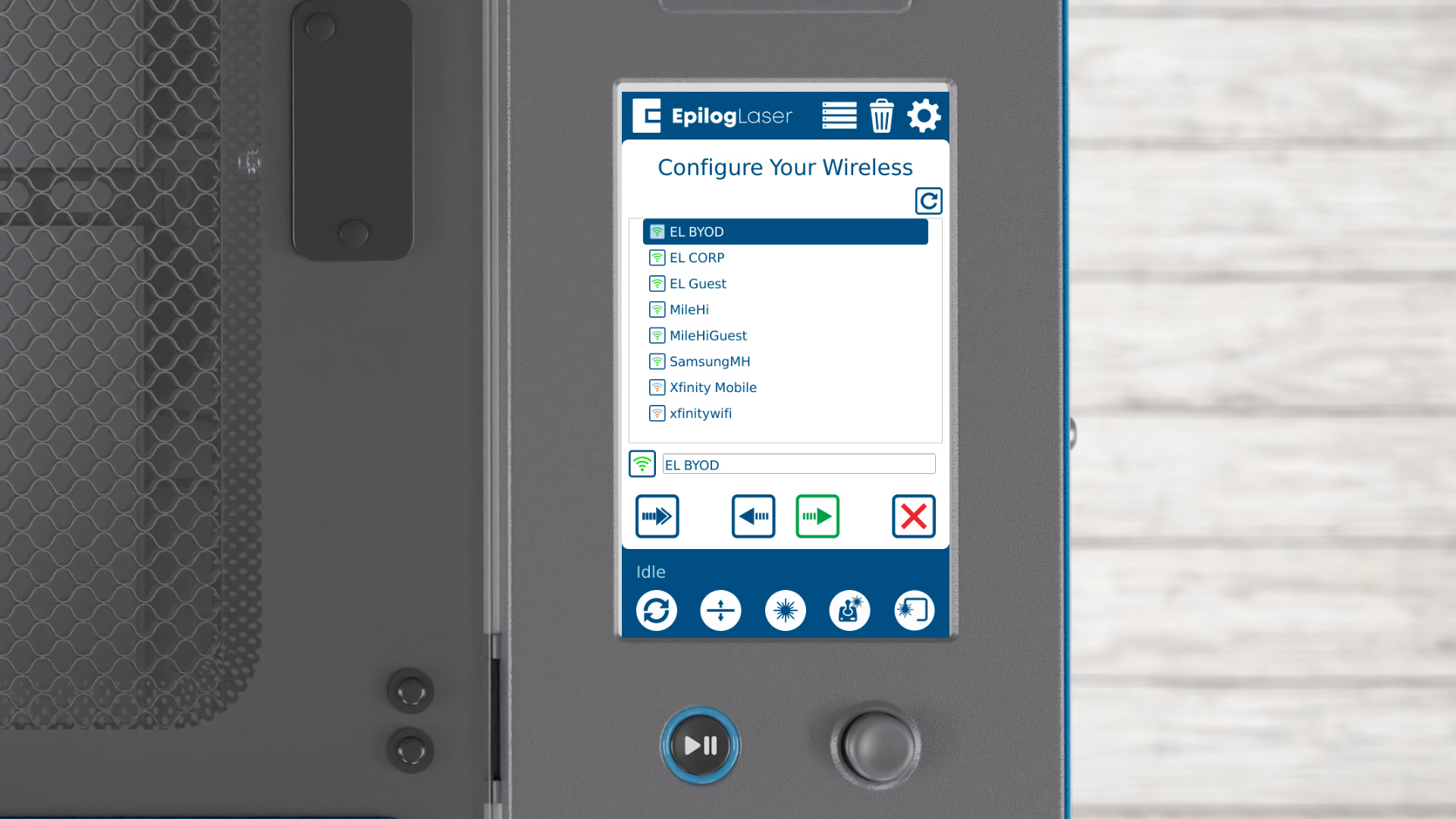
Select your wireless network.

Choose if your network uses WPA2 Personal or Open security, then press the arrow to continue.
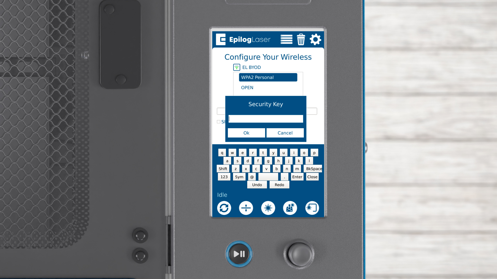
Enter your security key, then click Ok.
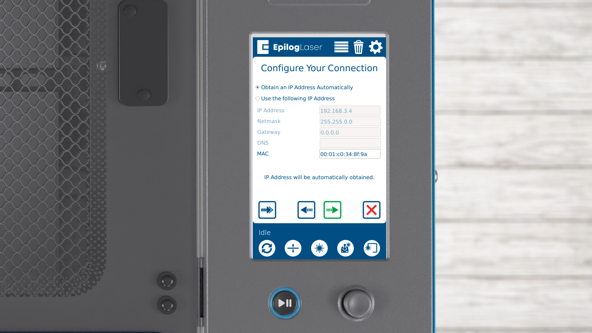
You can either automatically obtain an IP address or assign one manually. Press the arrow to continue
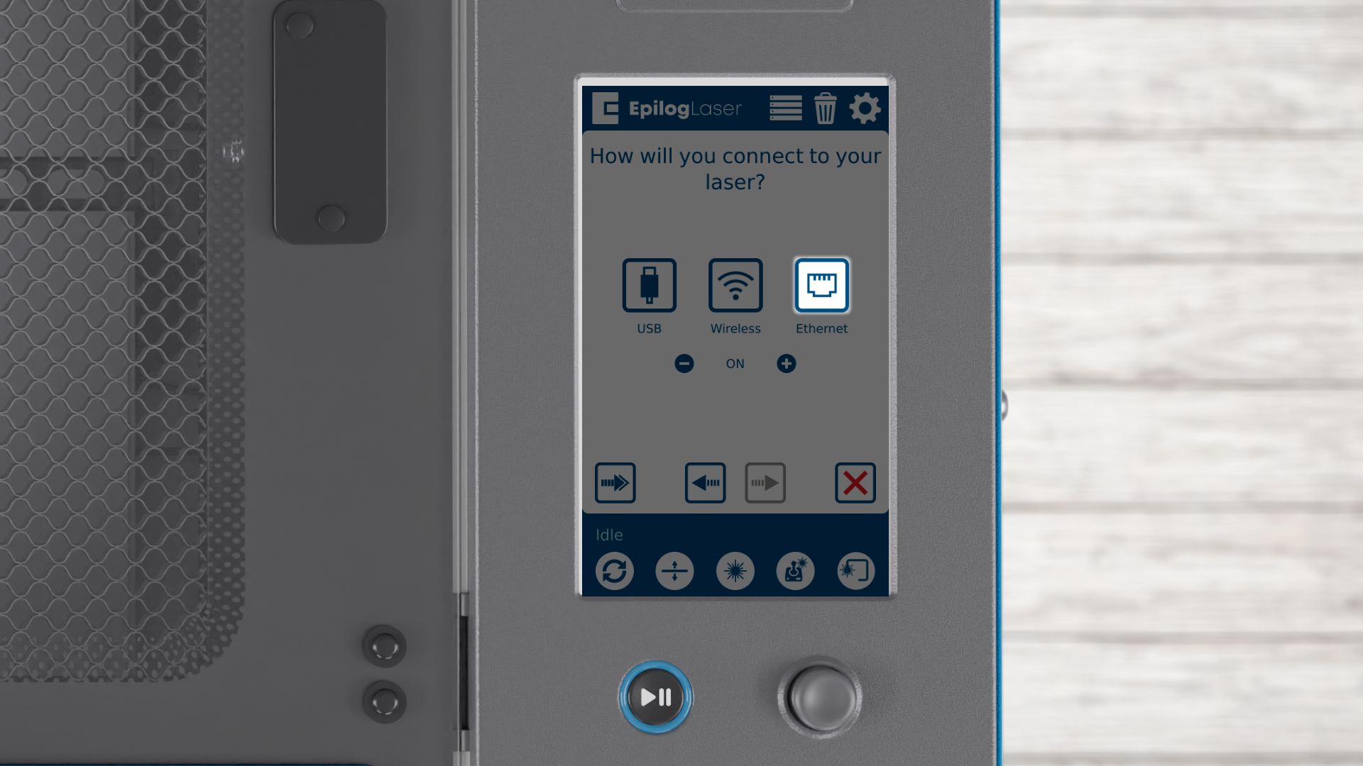
If you’re connecting by Ethernet cable, press the Ethernet button.
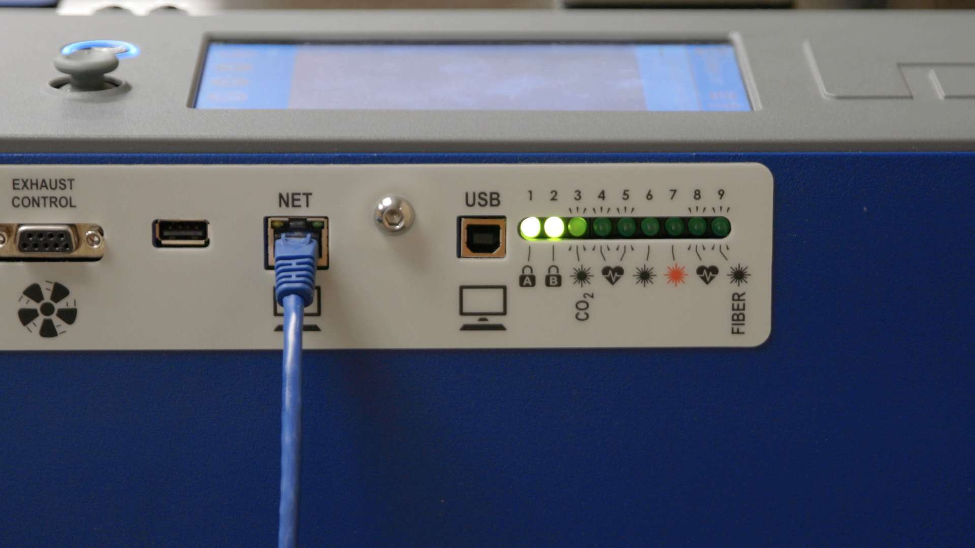
Connect the included Ethernet cable to your laser and the computer or network.
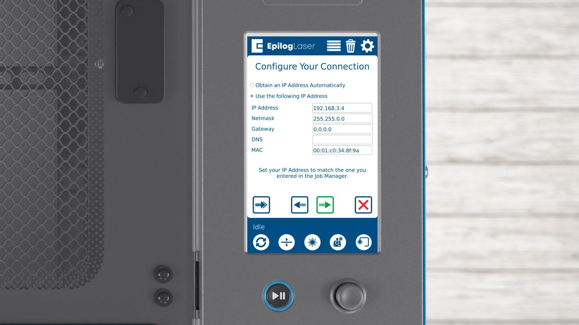
Just like with wireless, you can choose to obtain an IP address automatically or enter one manually. Press the arrow to continue.

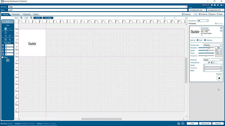
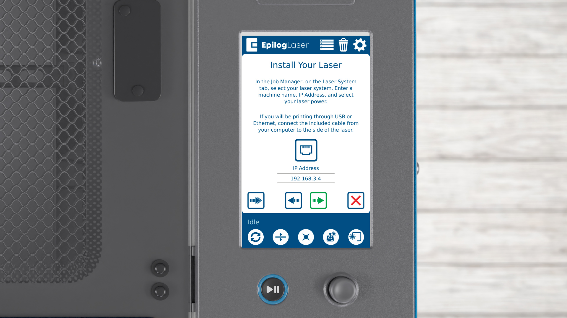
Once your connection is set up, the wizard will prompt you to install the Epilog Software Suite. Press the arrow to continue.

You’ll reference this IP address in the Software Suite. Now, let’s install the software suite.
Step 6: Firmware Installation
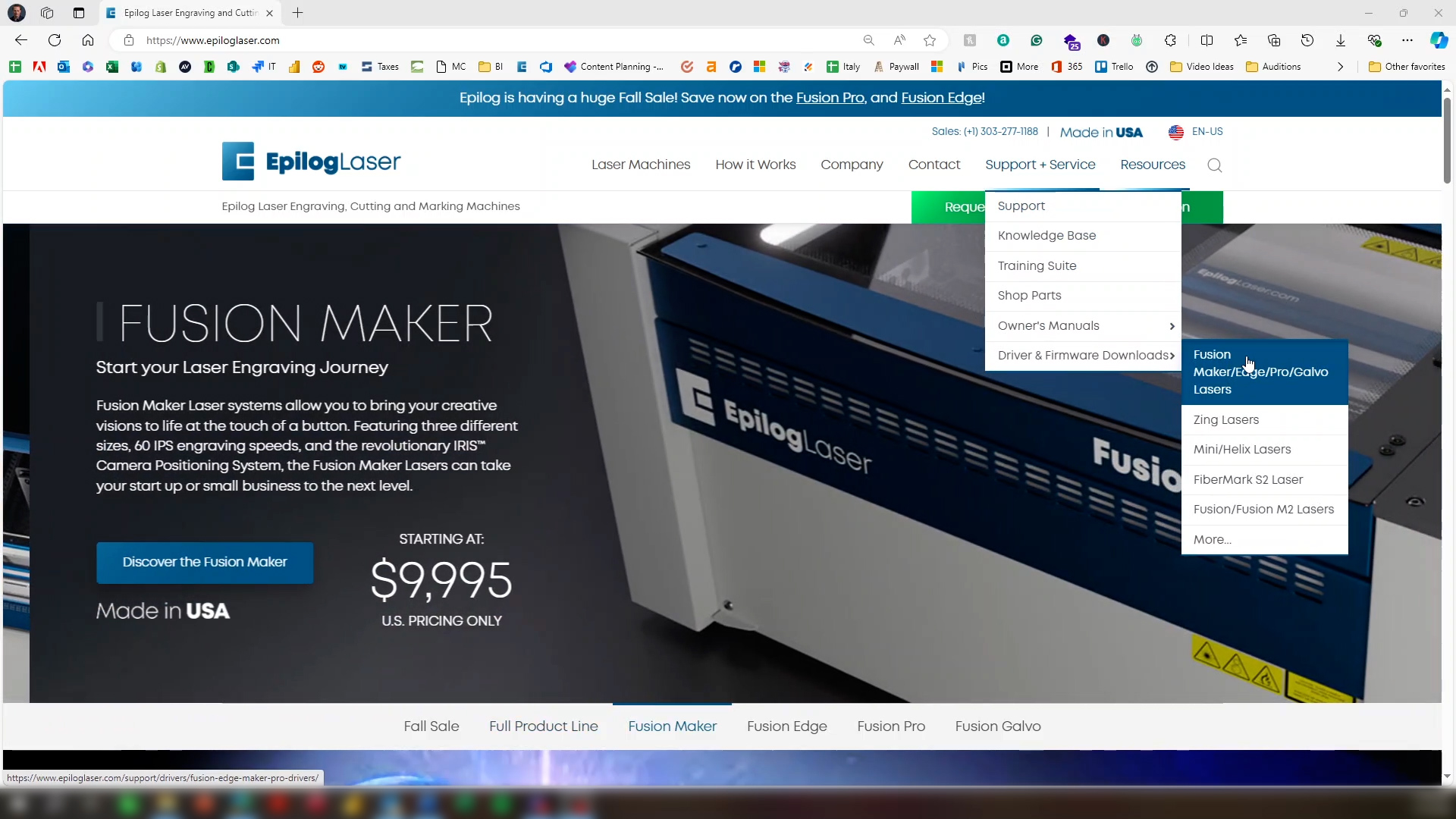
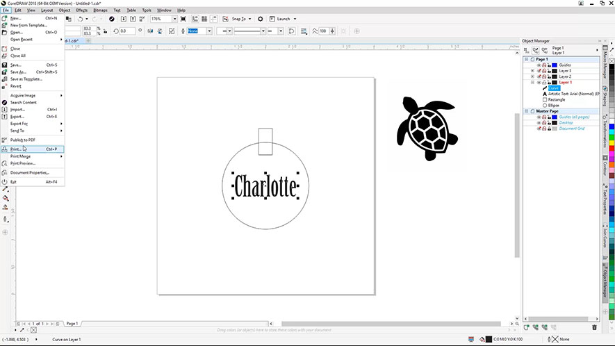
Visit Epilog’s website, go to Support, click Driver and Firmware Downloads, and select your laser system.
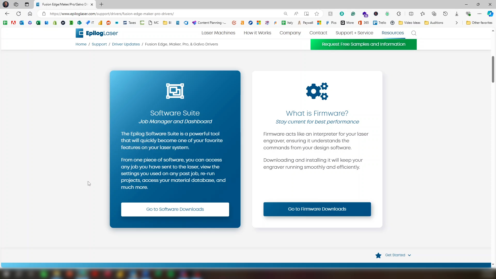
You’ll see two choices, to download the software suite, or the firmware. The firmware on a new system should be the latest available, so there is no need to download the firmware. Click Go to Software Downloads.
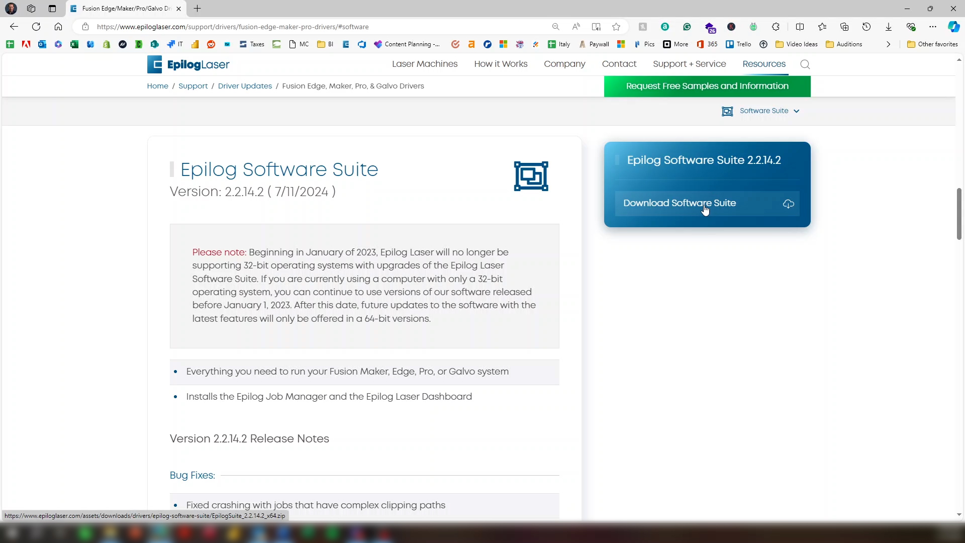
Click Download Software Suite.
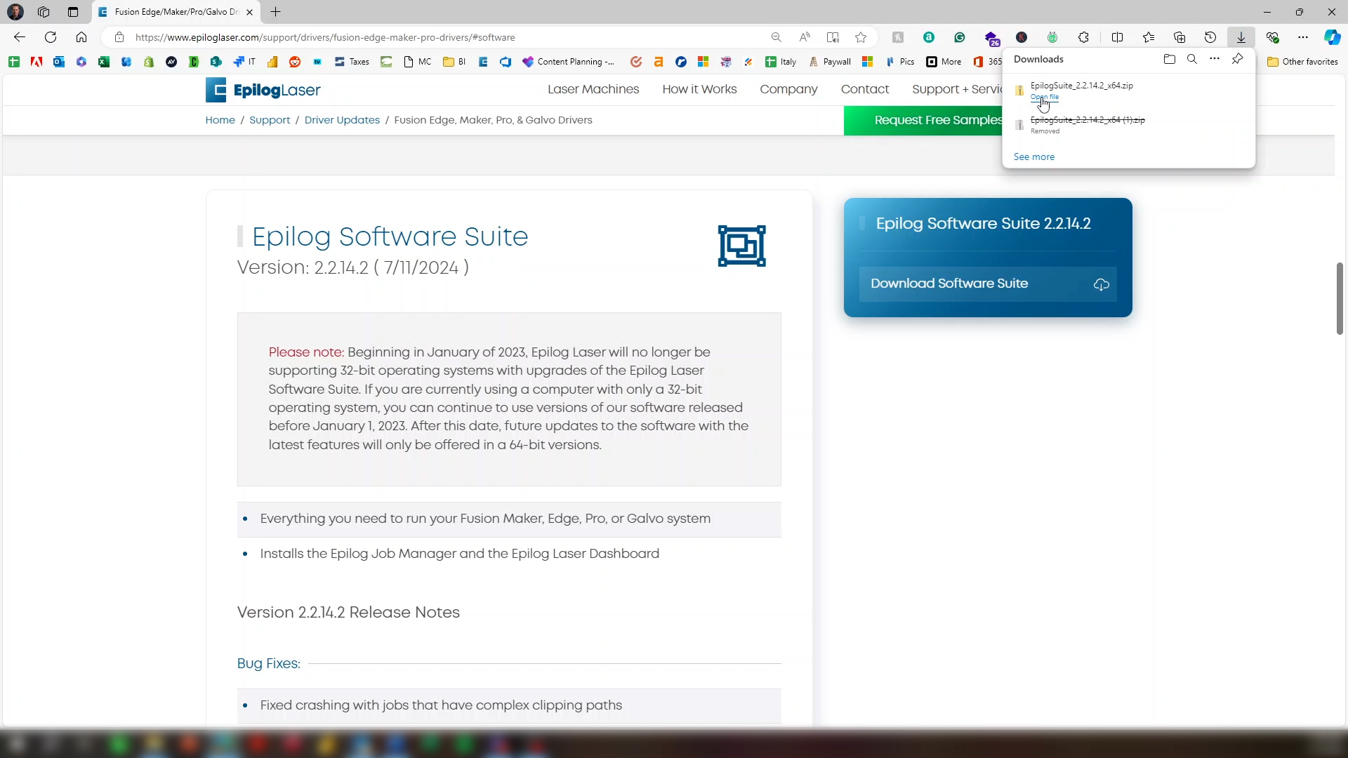
After the file downloads, open the file.
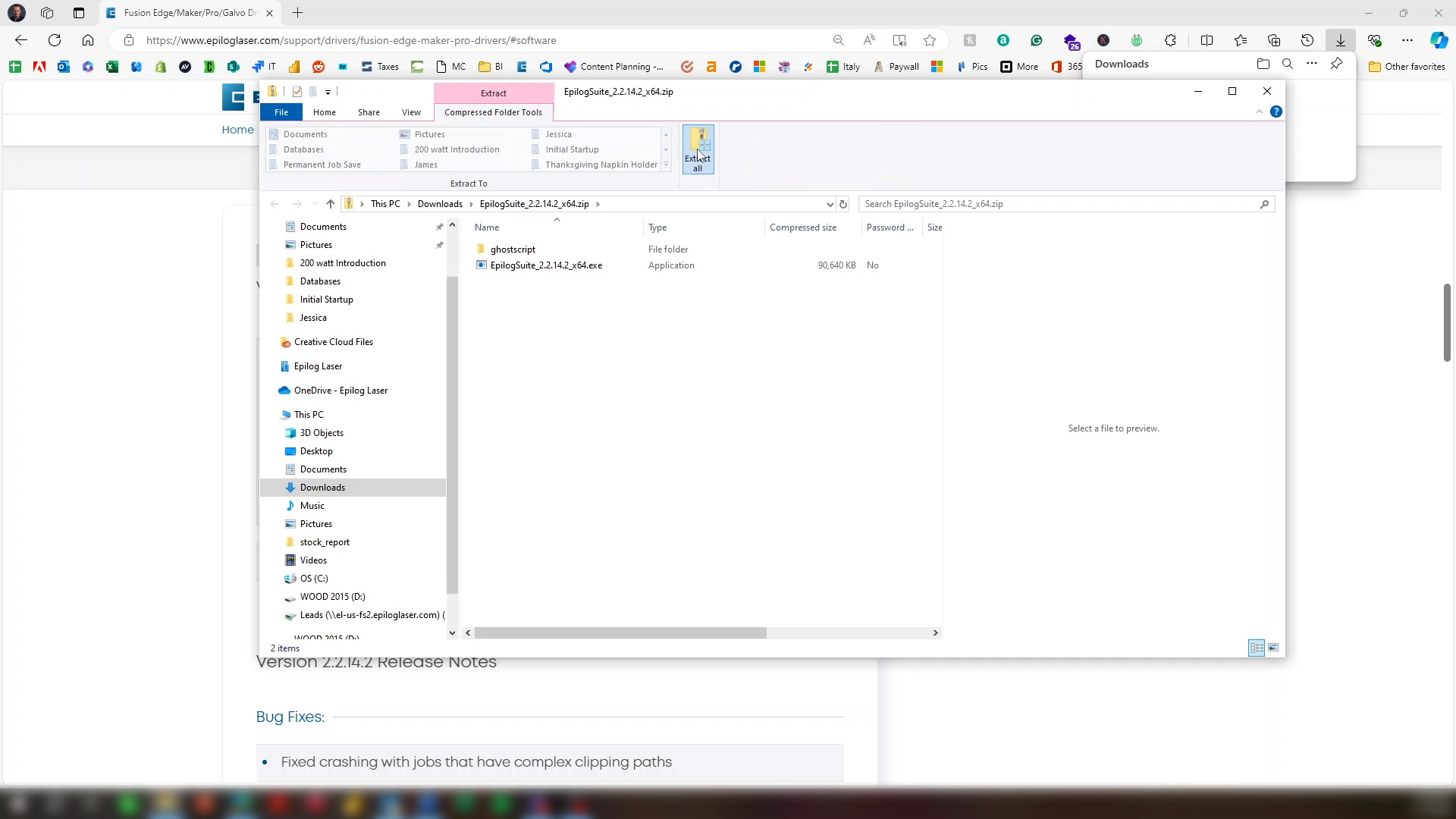
Select Extract All.
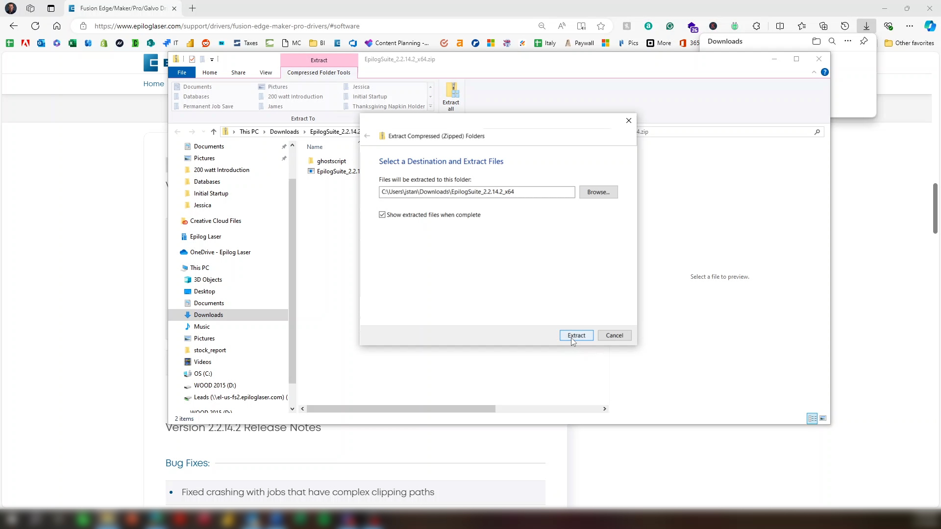
Click Show extracted files when complete, then click the Extract button.

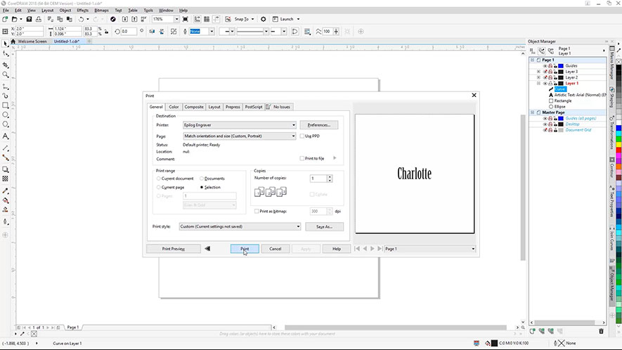
Double click the .exe file.
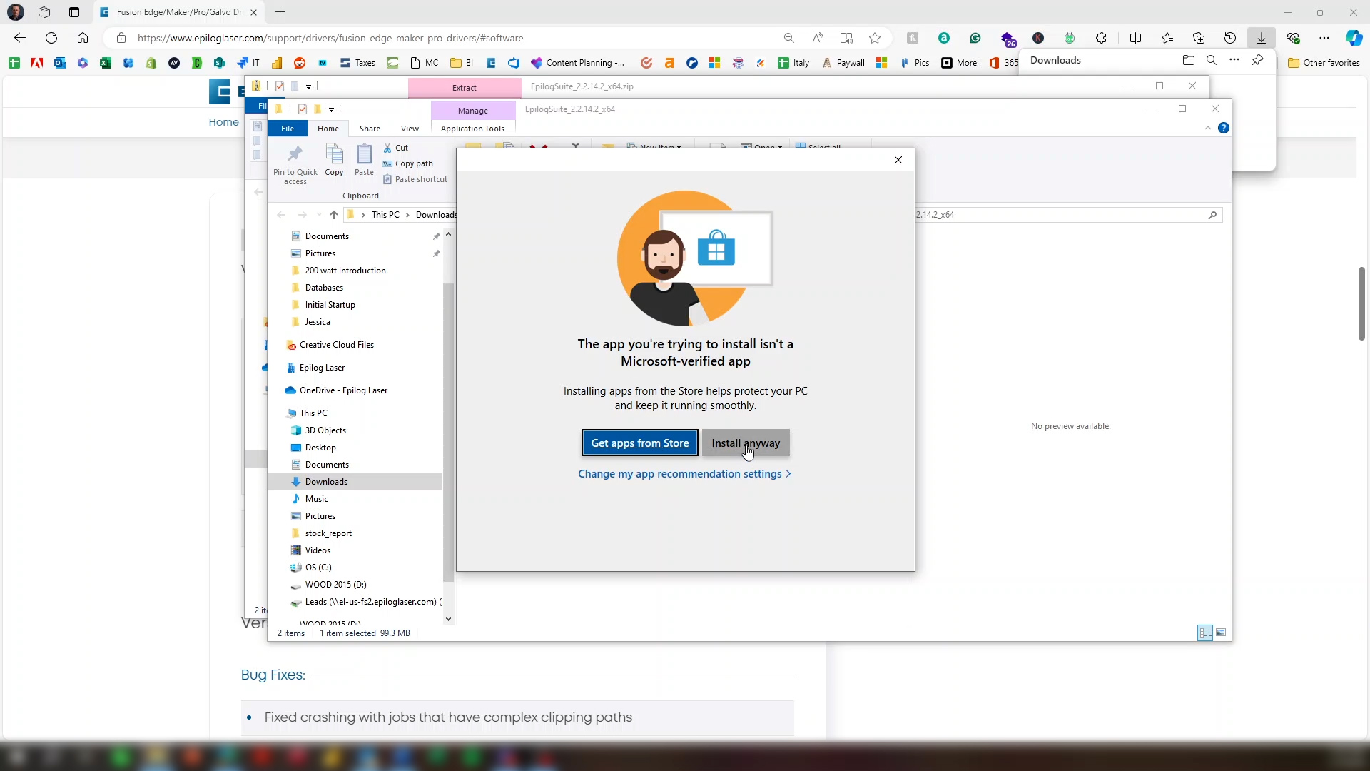
Click Install anyway.
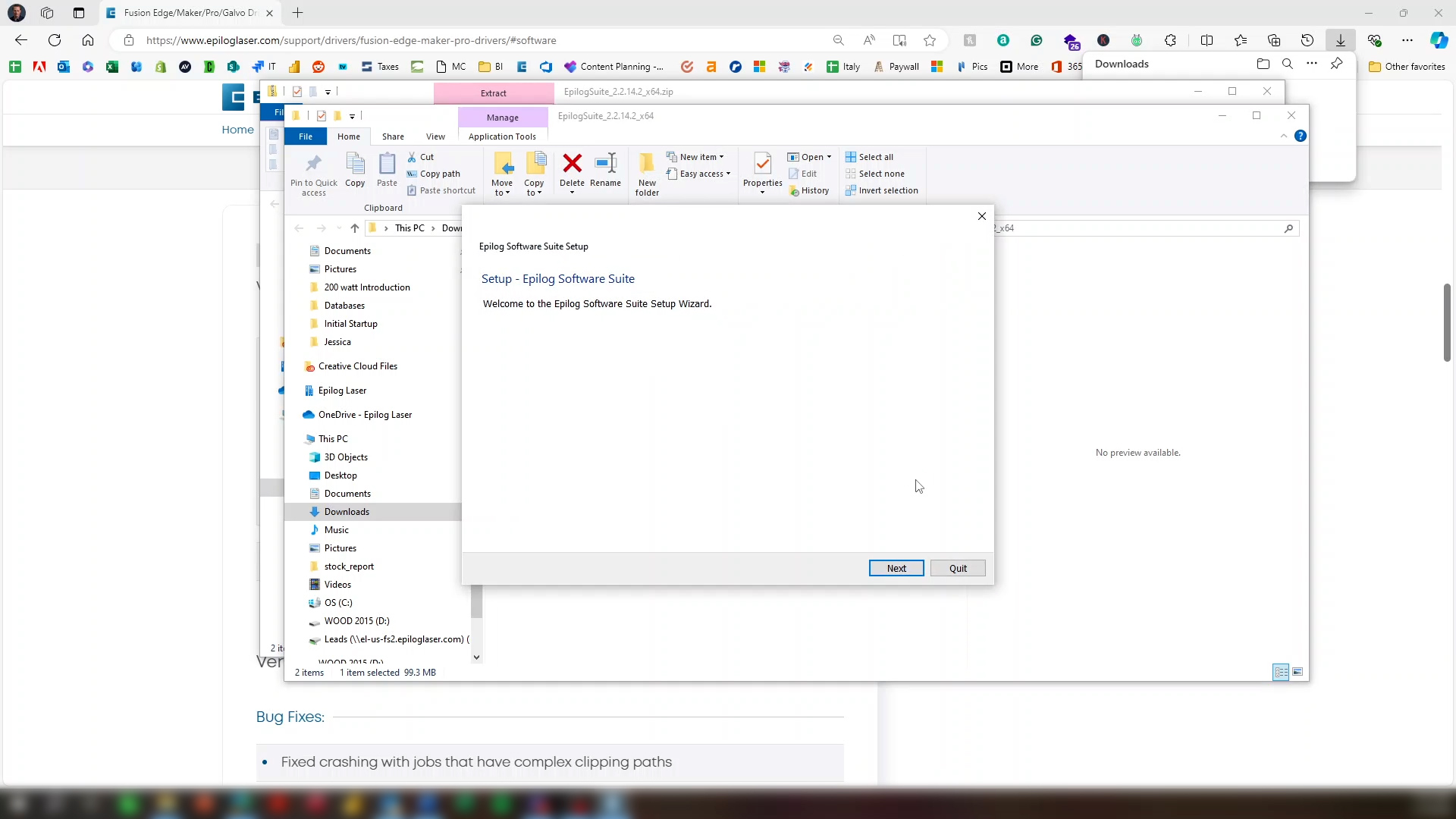
Click Next.
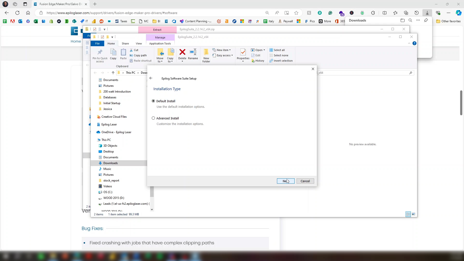
Click Next again.
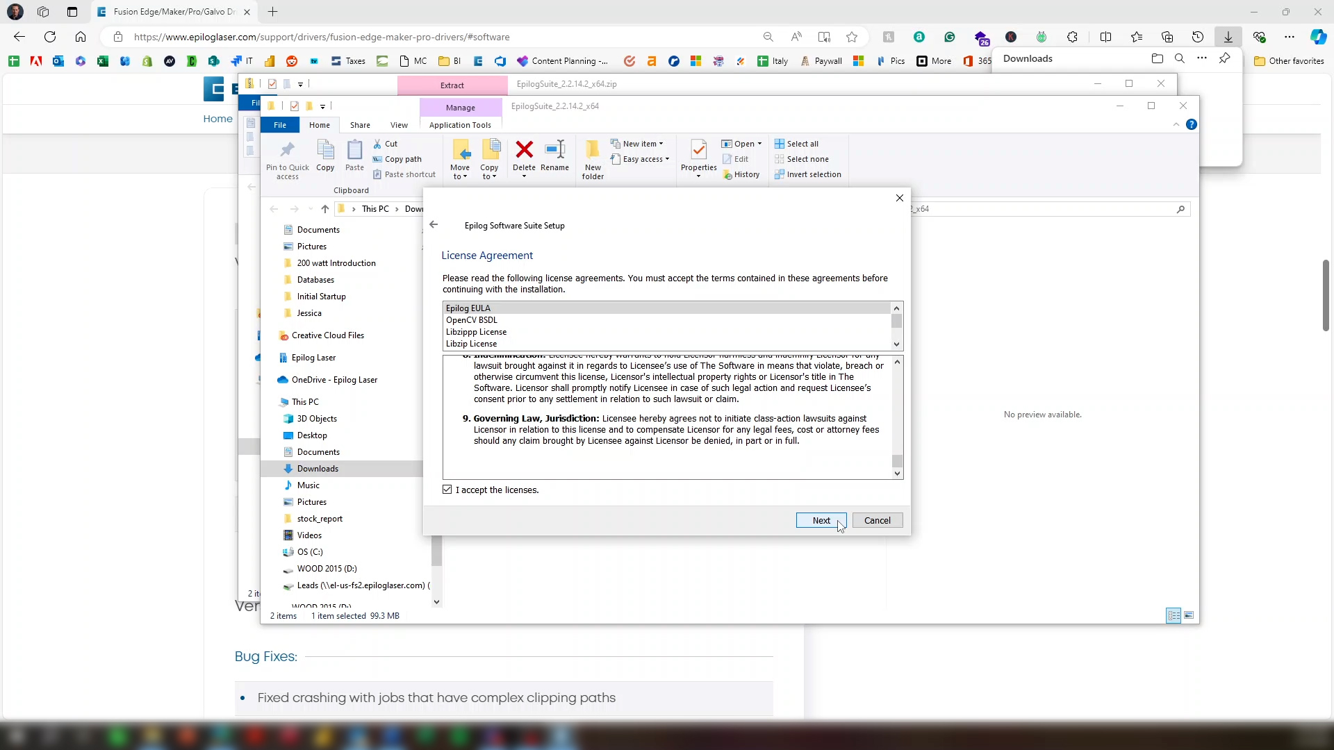
You can read the software license, then click “I accept the licenses”, then next.
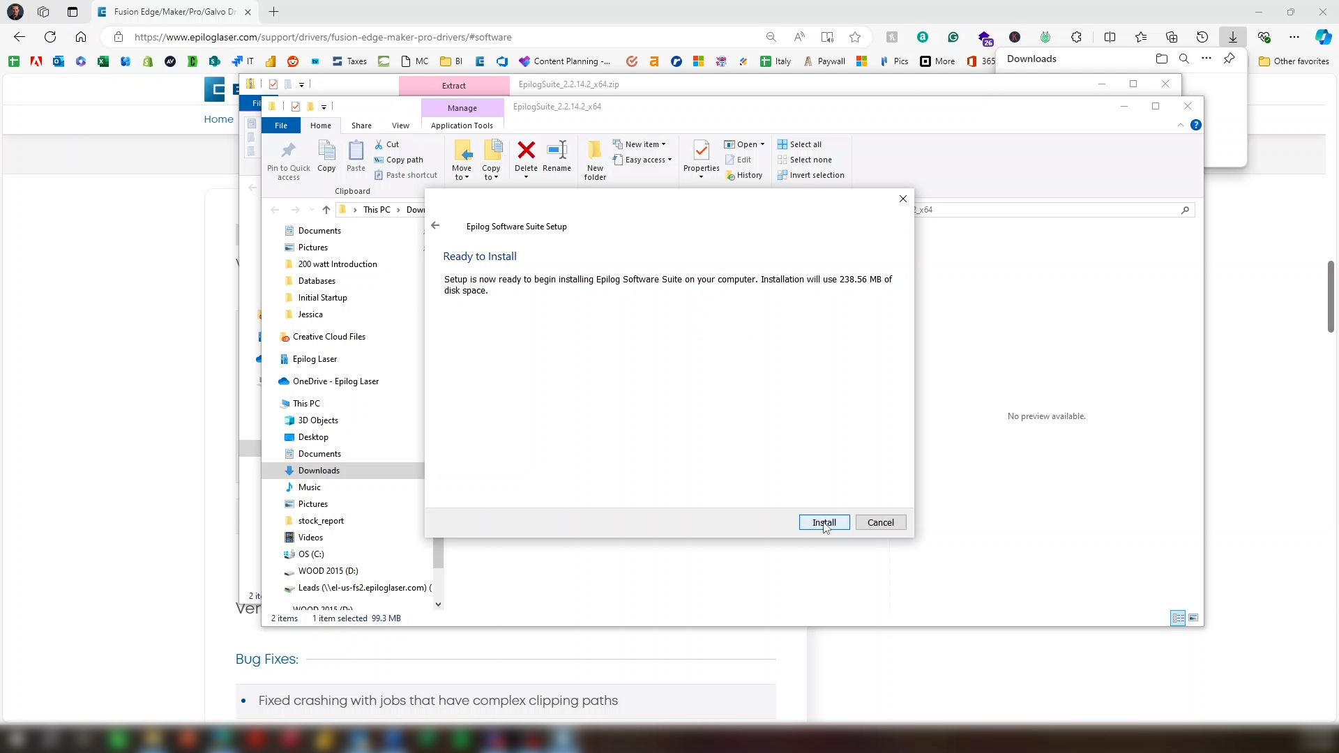
Click Install.
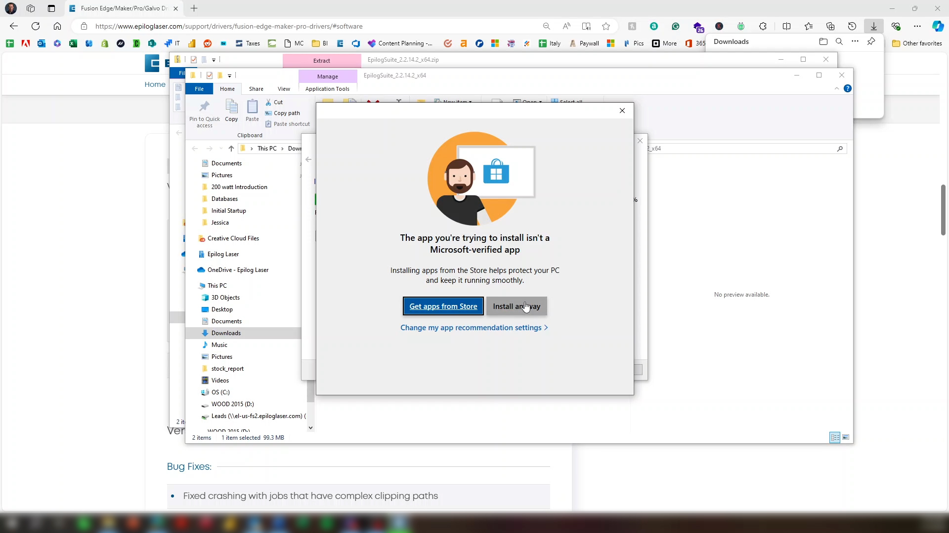
If a warning screen appears, click Install anyway.
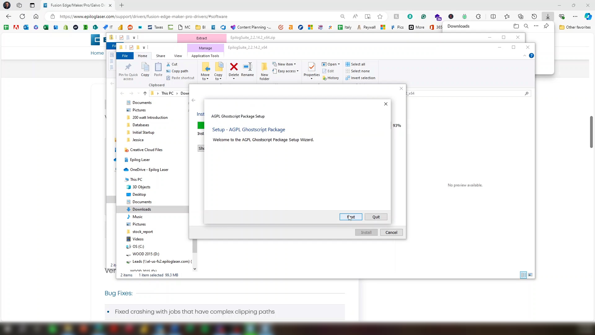
After the install is complete, click Next.
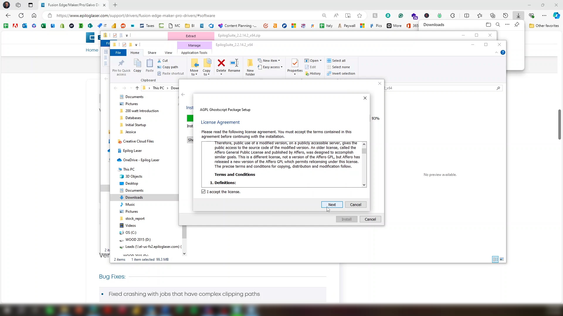
There will be another license that you can read. Click I accept the license, then next.
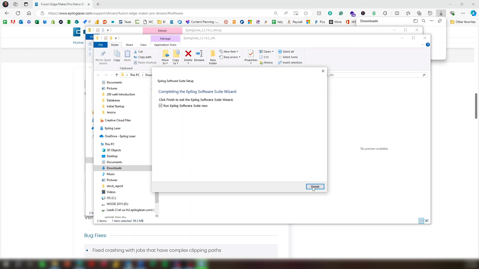
With Run Epilog Software Suite Now selected, click Finish.
Step 7: Add System to Job Manager
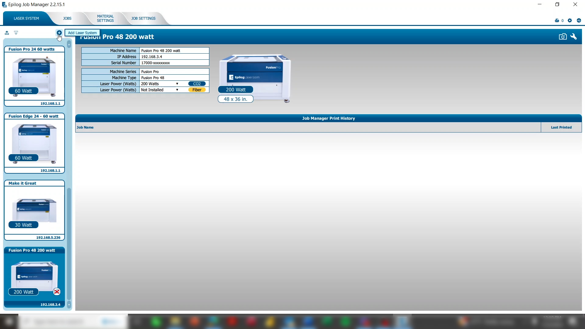
After installation, the Job Manager will open, and you’re ready to add your laser system. On the Laser System tab, click the plus button to add a laser system.
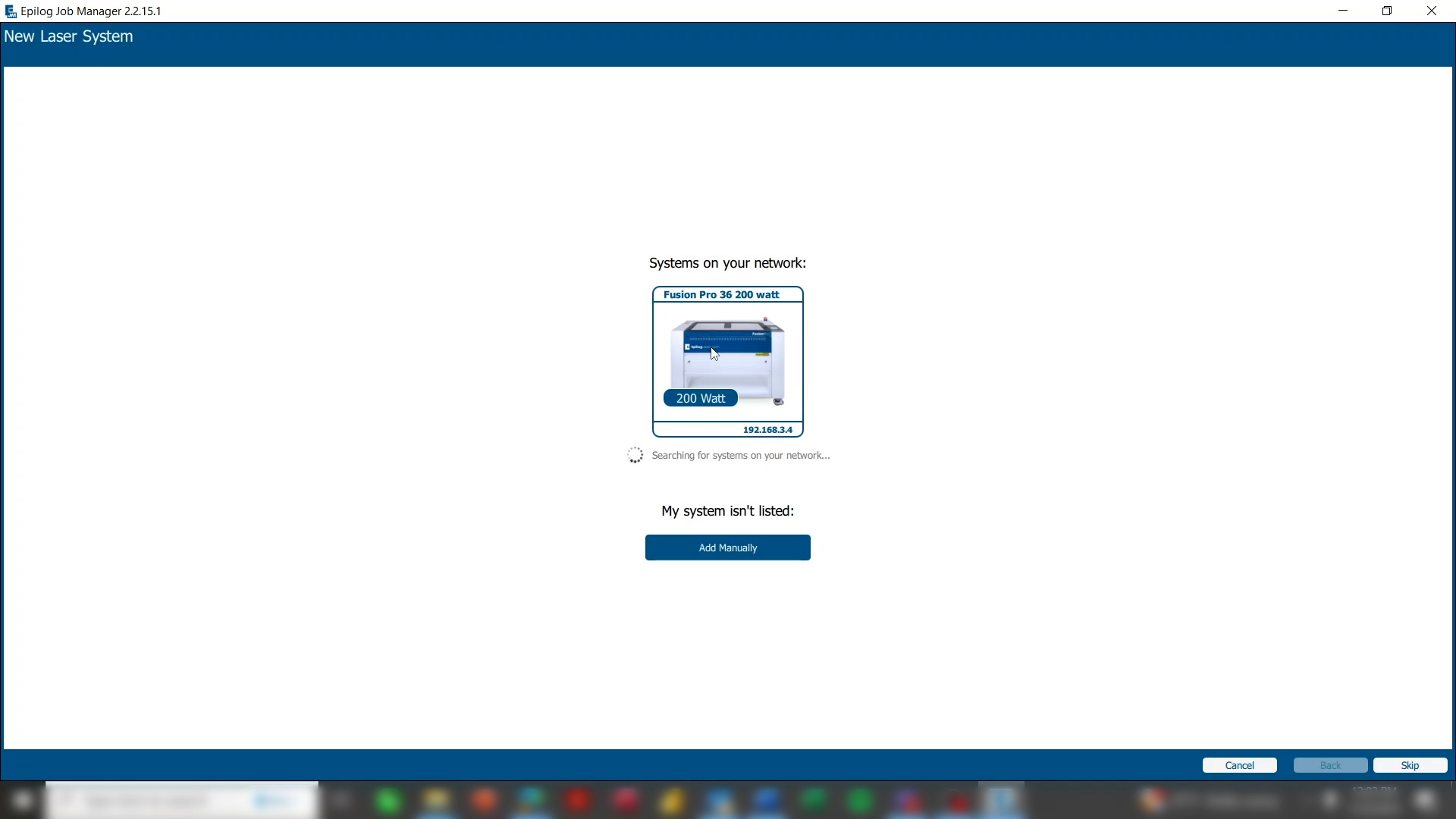
The system will search for any laser systems new to the network. Click on the image of the laser system.
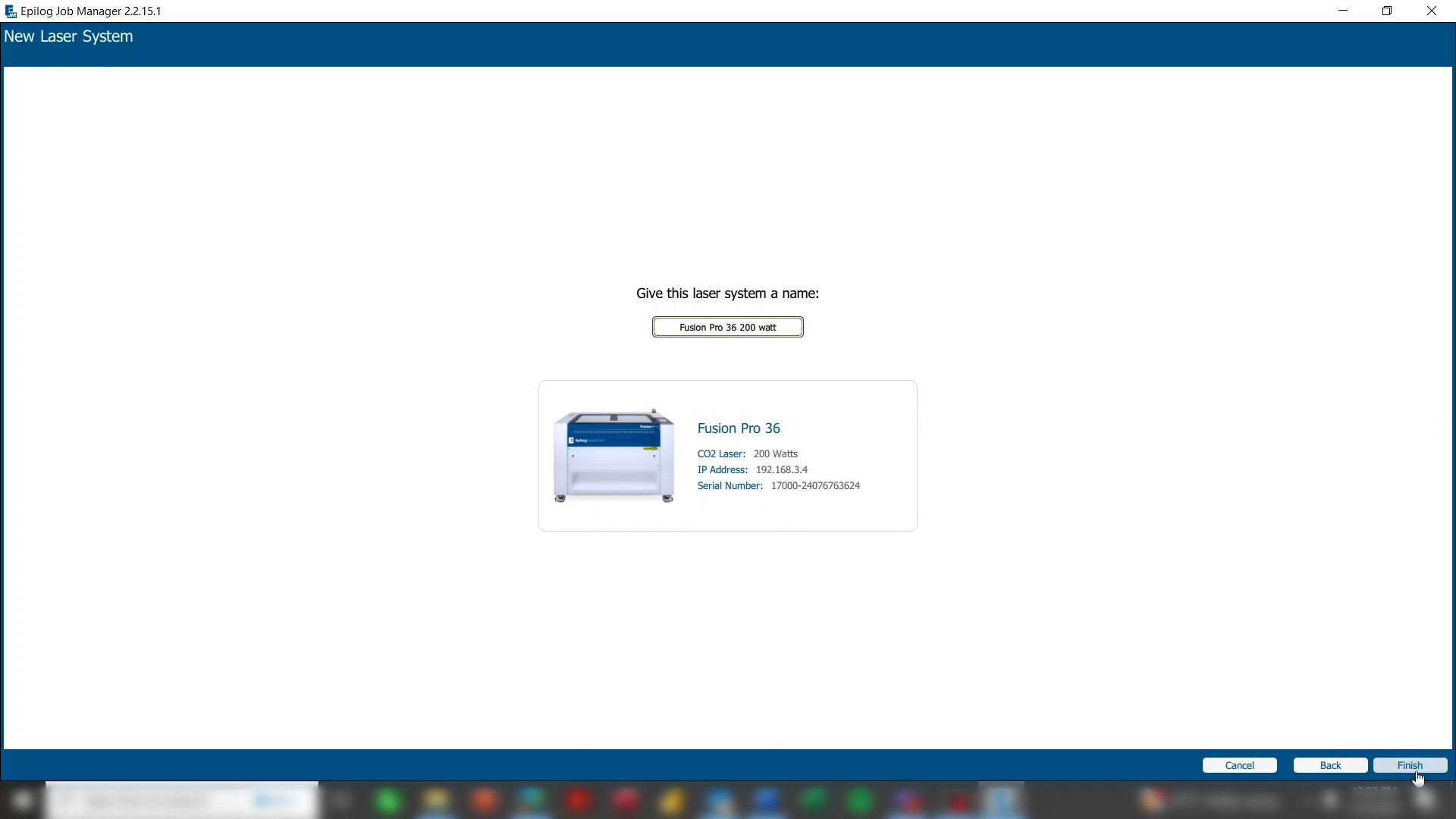
Click Finish.
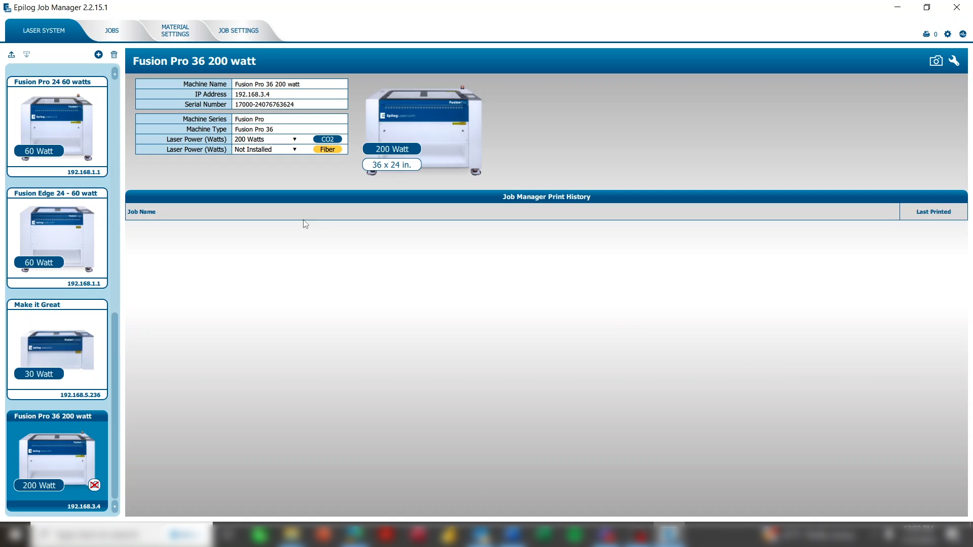
Now you can see your laser system has been added to your machine list with the IP address, wattage, and other information easily accessed.
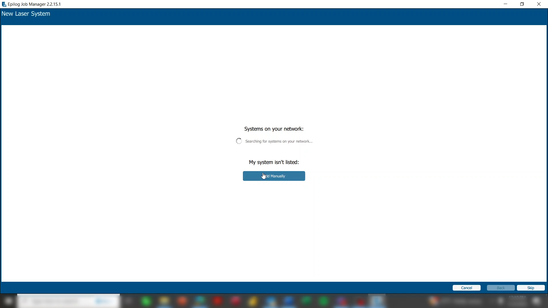
If the laser system isn’t automatically found, click Add Manually.
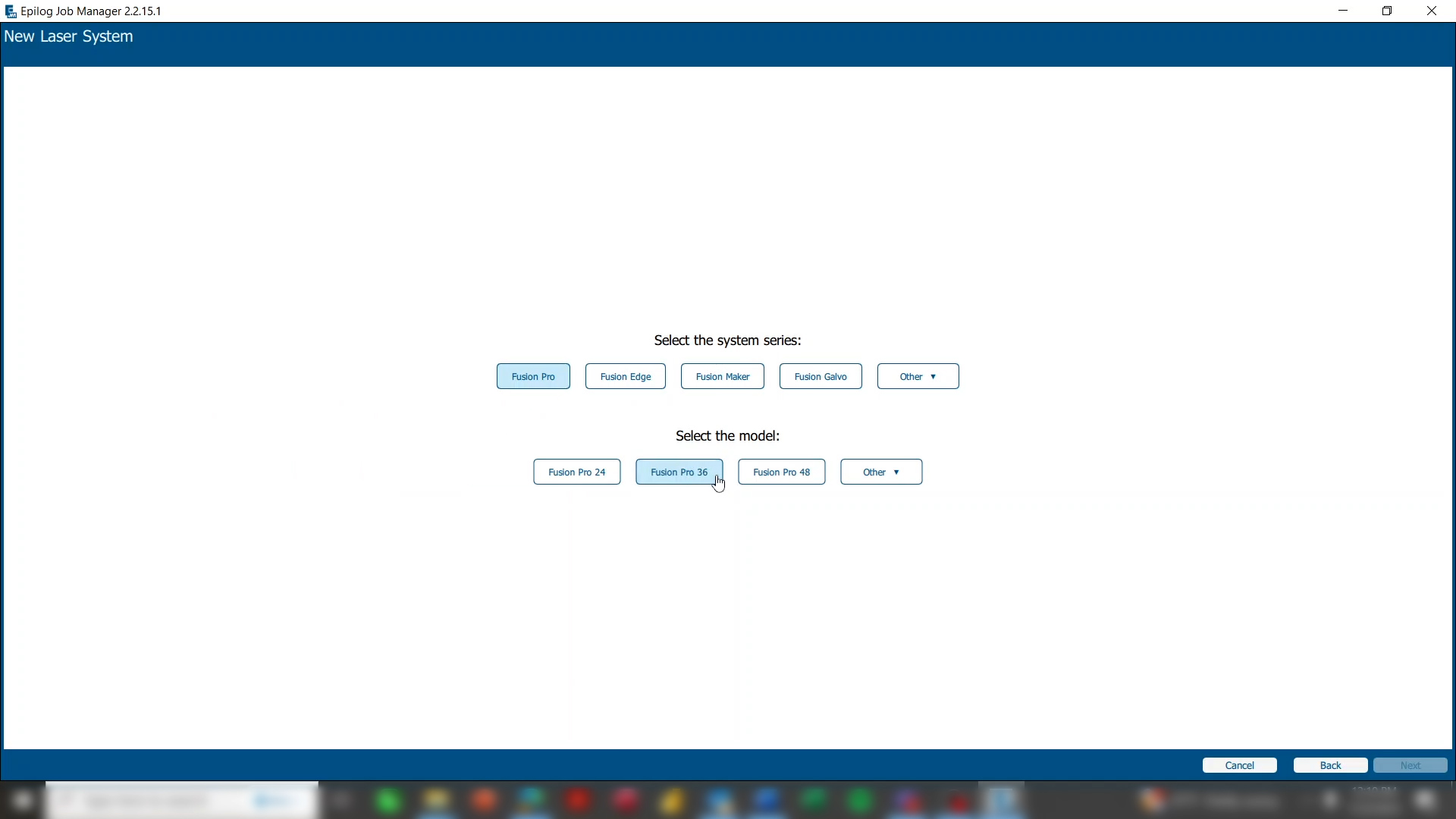
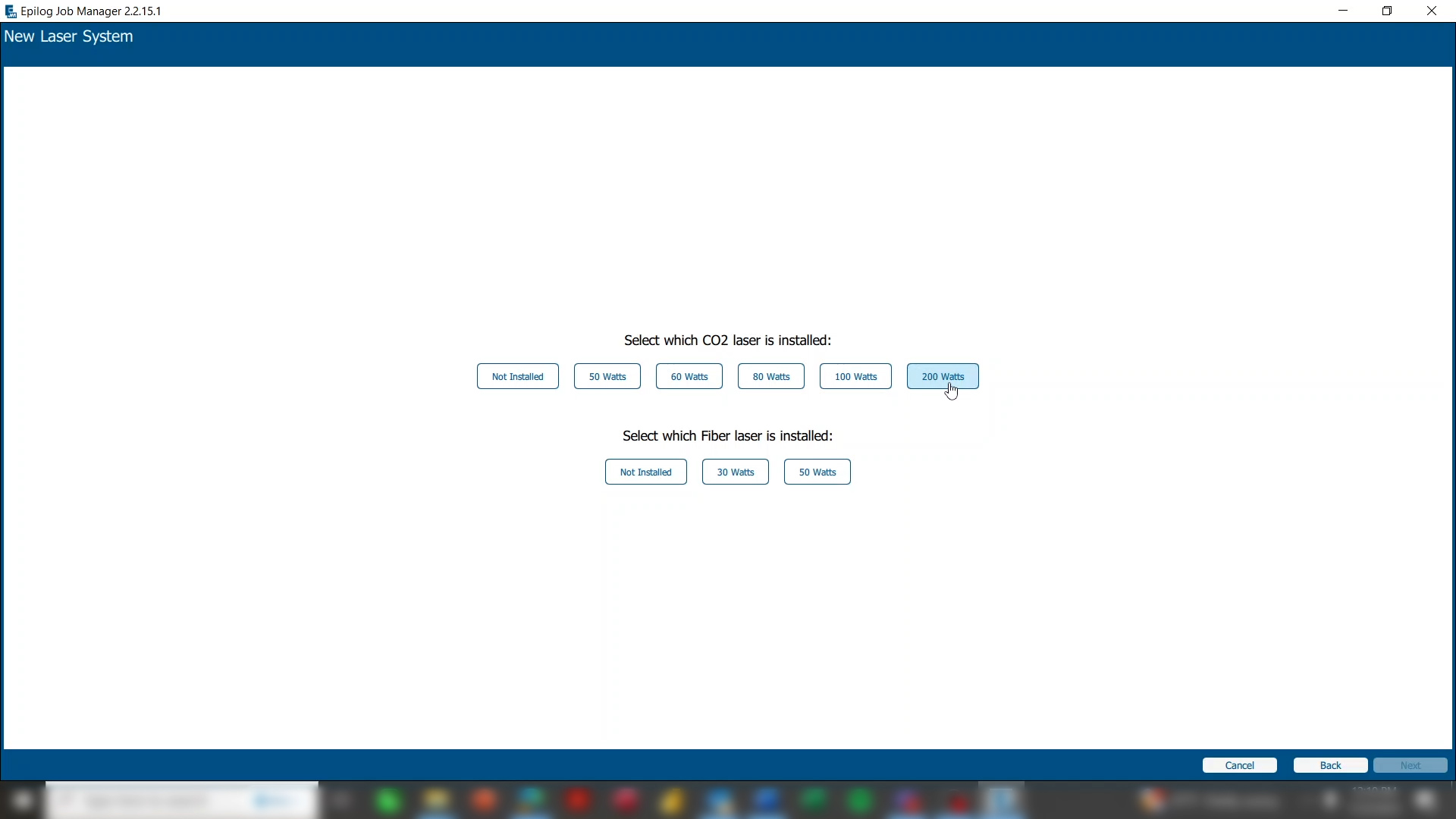
Choose your laser system and the wattage.
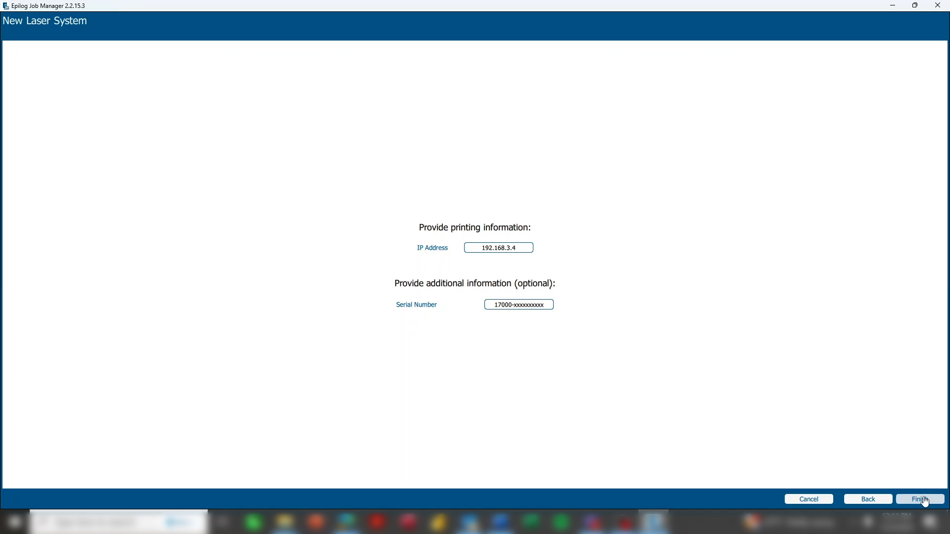
Then type in the IP address that is on the display panel of the laser. You can also enter your Serial Number for future reference or add this later.

Give the laser the same name you entered at the machine, and click finish.
Back on the display panel, press the arrow to continue.

You’ll be reminded that jobs are saved permanently on the machine only if you click the save icon. Press the arrow to continue.
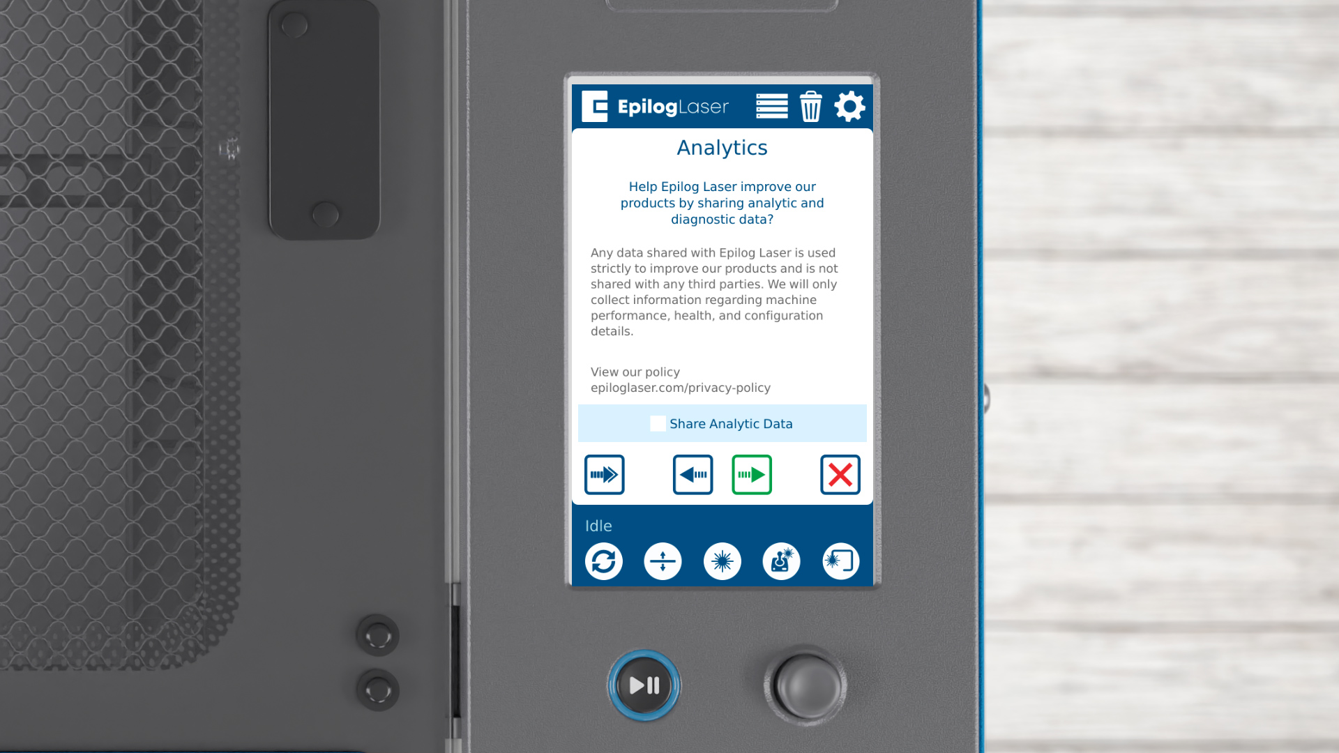
You can choose to opt-in for sharing analytics data with Epilog, which helps improve future software updates. Click the arrow to continue.
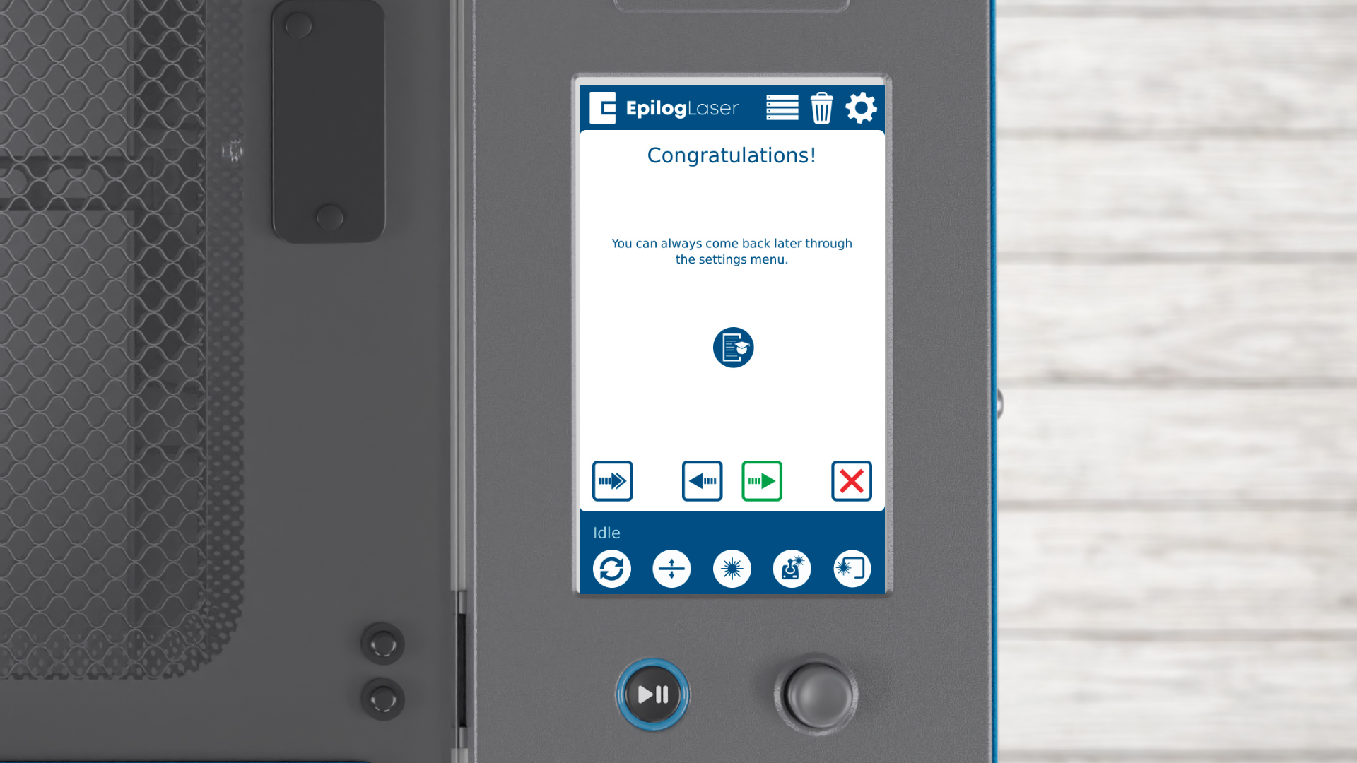
Everything we’ve set up today is also accessible in the settings menu at any time. Click the arrow to finish and start creating amazing projects with your Epilog Laser system!